EP0665512B1 - Bildverarbeitungsverfahren und -gerät - Google Patents
Bildverarbeitungsverfahren und -gerät Download PDFInfo
- Publication number
- EP0665512B1 EP0665512B1 EP95300591A EP95300591A EP0665512B1 EP 0665512 B1 EP0665512 B1 EP 0665512B1 EP 95300591 A EP95300591 A EP 95300591A EP 95300591 A EP95300591 A EP 95300591A EP 0665512 B1 EP0665512 B1 EP 0665512B1
- Authority
- EP
- European Patent Office
- Prior art keywords
- image
- data
- size
- decoding
- decoded
- Prior art date
- Legal status (The legal status is an assumption and is not a legal conclusion. Google has not performed a legal analysis and makes no representation as to the accuracy of the status listed.)
- Expired - Lifetime
Links
Images


Classifications
-
- G—PHYSICS
- G06—COMPUTING; CALCULATING OR COUNTING
- G06T—IMAGE DATA PROCESSING OR GENERATION, IN GENERAL
- G06T3/00—Geometric image transformation in the plane of the image
- G06T3/40—Scaling the whole image or part thereof
- G06T3/4084—Transform-based scaling, e.g. FFT domain scaling
-
- G—PHYSICS
- G06—COMPUTING; CALCULATING OR COUNTING
- G06T—IMAGE DATA PROCESSING OR GENERATION, IN GENERAL
- G06T9/00—Image coding
- G06T9/007—Transform coding, e.g. discrete cosine transform
Definitions
- the invention relates to an image processing method and apparatus and, more particularly, to an image processing method and apparatus dealing with a digital image encoded by block.
- the coded original image data is reproduced in an original size, then known interpolation processing, such as sub-sampling, has to be performed to complete the enlargement or reduction.
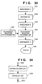
- Fig. 33 is a block diagram illustrating a constitution of a decoding and displaying processes in the conventional image processing apparatus.
- encoded data based on a discrete cosine transfer (DCT) using a block size of eight-pixel by eight-pixel, which is a block size of a still image standard encoding method, is stored in an image memory A 1501.
- the coded data is inputted to a decoding unit 1502, thereat the coded data is decoded in accordance with a decoding processing which will be described later. Then, the decoded data is stored in an image memory B 1503.
- DCT discrete cosine transfer
- the decoded image data stored in the image memory B 1503 is inputted to an enlargement/ reduction processing unit 1504 where the image data is applied to an enlargement/reduction process, such as a sub-sampling or such interpolation processing, based on an enlargement/reduction ratio designated by an enlargement/reduction ratio designator 1507.
- an enlargement/reduction process such as a sub-sampling or such interpolation processing
- the image data is stored in an image memory C 1505 for display (a display memory).
- the processed data stored in the image memory C 1505 is displayed on a display 1506.
- Fig. 34 an example of a conventional decoding unit 1502 shown in Fig. 33 is illustrated.
- an 8 ⁇ 8 DCT coded data is decoded.
- the coded data is inputted to a Huffman decoding unit 1601 via an input terminal 1600, and decoded, then 8 ⁇ 8 DCT coefficients are reproduced.
- the reproduced DCT coefficients are inputted into an inverse DCT unit 1602 and applied with an inverse DCT process, then an image data of an 8 ⁇ 8 block size is reproduced.
- the reproduced image data is outputted to the image memory B 1503 in Fig. 33 via an output terminal 1603.
- all the DCT coded data is converted to image data of an original size by decoding the coded data, then enlarged or reduced.
- Laplacean Pyramid coding method As a typical hierarchical coding method used by a conventional image processing apparatus, there is the well-known Laplacean Pyramid coding method as disclosed in IEEE TRANSACTIONS ON COMMUNICATIONS, APRIL 1983, USA, vol. COM-31, no.4, ISSN 0090-6778, pages 532-540, BURT P J ET AL 'The Laplacean Pyramid as a Compact Image Code'.
- an input image is hierarchically compressed from 1/2, 1/4, 1/8, and so on, and at each hierarchy of the pyramid, a compressed image is coded by using the discrete cosine transfer, or the like.
- the order of encoding is to encode the most compressed image, then encode the difference between the image expanded to doubled the size of the decoded image corresponding to the most compressed image and the image compressed to the aforesaid "doubled" size obtained from the input image.
- the aforesaid process is repeated until the image size of the hierarchy which is the subject to encode and the input image becomes the same size, thereby coded data of multi-hierarchical images can be generated.
- Coded data of each hierarchy of the hierarchical coding method such as the Laplacean pyramid coding method as described above, is generated by coding a part of the decoded original image data. Then, by decoding coded data of each hierarchy, the lower hierarchical image can be obtained as, for instance, a reduced image.
- FIG. 35 is a block diagram illustrating a structure of an image processing apparatus capable of using the conventional hierarchical coding method.
- reference numeral 101 denotes a decoder, which reproduce RGB image data from image data, encoded by a DCT sequential encoder (not shown), as an input, by performing decoding, inverse-quantizing, inverse DCT, and color conversion.
- the RGB image data outputted from the decoder 101 is sub-sampled to a size of 1/2 in the vertical and horizontal directions by a sub-sampling unit A 102, thereby an image of 1/4 (1/2 ⁇ 1/2) size of the original image is produced.
- the sub-sampled RGB image data is further sub-sampled to a 1/2 size in the vertical and horizontal directions, and a 1/16 (1/4 ⁇ 1/4) size image of the original image is produced.
- the RGB image data from the sub-sampling unit B 103 is further sub-sampled to a 1/2 size in the vertical and horizontal directions, then an image of 1/64 (1/8 ⁇ 1/8) size of the original image is obtained.
- the 1/8 ⁇ 1/8 size image outputted from the sub-sampling unit C 104 is encoded at a CODEC A 105 which generates coded data of 1/8 ⁇ 1/8 size. Further, the CODEC A 105 output locally decoded image data to an interpolation processing unit A 106.
- the interpolation processing unit A 106 applies interpolation processing on the decoded 1/8 ⁇ 1/8 size image data to expand it to a doubled size image data, then output the obtained data to a subtractor 107.
- the subtractor 107 finds the difference between the doubled 1/8 ⁇ 1/8 size image data outputted from the interpolation processing unit A 106 and the 1/4 ⁇ 1/4 size image data outputted from the sub-sampling unit B 103, then the obtained difference is outputted to a CODEC B 108.
- the CODEC B 108 encodes the 1/4 ⁇ 1/4 size image which is inputted from the subtractor 107, thus the difference between the 1/8 ⁇ 1/8 size image and the 1/4 ⁇ 1/4 size image is encoded, and 1/4 ⁇ 1/4 size coded data is generated.
- the CODEC B 107 outputs the locally decoded image data to an adder 109.
- the adder 109 adds the 1/4 ⁇ 1/4 size image data from the CODEC B 108 to the 1/4 ⁇ 1/4 size image data outputted from the interpolation processing unit A 106, and the obtained sum is expanded to a doubled size image data at a interpolation processing unit B 110, then outputted to a subtractor 111.
- the subtractor 111 calculates difference between the doubled 1/4 ⁇ 1/4 size image data outputted from the interpolation processing unit B 110 and the 1/2 ⁇ 1/2 size image data outputted from the sub-sampling unit A 102, then the obtained difference is outputted to a CODEC C 112.
- the CODEC C 112 encodes the 1/2 ⁇ 1/2 size image inputted from the subtractor 111, in other words, the difference between the 1/4 ⁇ 1/4 size image and the 1/2 ⁇ 1/2 size image is encoded, then the CODEC C 112 generates 1/2 ⁇ 1/2 size coded data. Further, the CODEC C 112 outputs the locally decoded image data to an adder 113.
- the adder 113 adds the 1/2 ⁇ 1/2 size image data outputted from the CODEC C 112 to the 1/2 ⁇ 1/2 size image data from the interpolation processing unit B 110, the sum is expanded to a double size image data at a interpolation processing unit C 114, then outputted to a subtractor 115.
- the subtractor 115 finds the difference between the doubled 1/2 ⁇ 1/2 size image data outputted from the interpolation processing unit C 114 and the full size image data from the decoder 101, then the obtained difference is outputted to a CODEC D 116.
- the CODEC D 116 encodes the full size image inputted from the subtractor 115, in other words, the difference between the 1/2 ⁇ 1/2 size image and the full size image is encoded to generate full size coded data.
- the detailed configurations of CODEC A 105, the CODEC B 108, the CODEC C 112, and the CODEC D 116 in Fig. 35 are basically same except for the amount of memory which is used in each processing stage.
- Fig. 36 is a block diagram showing the detailed configuration of the CODEC.
- an input image is a decoded RGB signal, and converted from the RGB signal to a luminance/color difference (YUV) signal at a color converter A 117, then applied with 8 ⁇ 8 DCT process on each color signal at a DCT unit 118.
- the DCT coefficients obtained at the DCT unit 118 are linearly quantized, and are coded in accordance with the Huffman coding method at the encoding unit 120, thereby coded data is outputted.
- the output from the quantizing unit 119 is also sent to an inverse-quantizing unit 121 to be inverse-quantized, and the processed data is changed to DCT coefficient data.
- an inverse DCT unit 122 8 ⁇ 8 inverse DCT process is applied to the DCT coefficient data, then a YUV signal is generated.
- the YUV signal is converted into a RGB signal at color converting unit B 123.
- the output via the inverse-quantizing unit 121, the inverse DCT unit 122, and the color converter B 123 are local decode output from each CODEC shown in Fig. 35.
- sequential coding data is converted into, for instance, hierarchical coded data of four hierarchies.
- a process for converting from the hierarchical coded data into sequential coded data is performed by reversing the process which is described above.
- n/8 ⁇ n/8 (n ⁇ 8; n is a positive integer) size reduced image by extracting a n ⁇ n matrix portion from the 8 ⁇ 8 DCT coefficients.
- n is a positive integer
- the image memory B 1503 and the enlargement/reduction processing unit 1504 of the conventional configuration shown in Fig. 33 become unnecessary, and image data outputted from the inverse DCT unit 1602 is directly outputted to the image memory C 1505, shown in Fig. 33, via the output terminal 1603.
- the enlargement/reduction ratio designator 1507 is connected to the inverse DCT unit 1602, shown in Fig. 34, of the decoding unit 1502.
- coded data of plural hierarchies when coded data whose hierarchy is closer to the designated reduction ratio is decoded, and reduced or enlarged in accordance with the designated reduction ratio, then a desired size image data is obtained.
- the invention is particularly advantageous since it is possible to generate a compressed image of an original from DCT coded data at high speed without using a memory of large capacity.
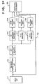
- Fig. 1 is a block diagram illustrating an example of a structure of a unit which encodes and displays in an image processing apparatus according to a first embodiment.
- reference numeral 10 denotes an image memory A, and stores 8 ⁇ 8 DCT coded data, especially data encoded by an ADCT method defined in JPEG.
- the coded data is sent from the image memory A 10 to a Huffman decoding unit 11, thereat decoded to DCT coefficients for each block with reference to an ACend signal 17 which will be explained later.
- the Huffman decoding unit 11 in the first embodiment will be explained later in detail. It should be noted that if decoding process of DCT coefficients is terminated in the middle of the process, the decoding process of the next block can start. Then, the DCT coefficients decoded in the Huffman decoding unit 11 is sent to an inverse DCT unit 12.
- the inverse DCT unit 12 is able to perform inverse DCT process of n ⁇ n size (n ⁇ 8; n is a positive integer) referring to a DCT matrix signal 18, which will be described later, and an image data is reproduced by applying the inverse DCT process on the DCT coefficients inputted from the Huffman decoding unit 11, and outputted to an image memory B 13.
- the image memory 13 is for storing image data necessary for display, and a display 14 displays an image based on the image data stored in the image memory B 13.
- Reference numeral 15 denotes an enlargement/reduction ratio designator (referred as "ratio designator” hereinafter) for designating an enlargement or reduction ratio (referred as “ratio” hereinafter) between an image to be reproduced and an original image.
- the ratio designator 15 decides the ratio Z, and outputs it to a DCT matrix selector 16.
- the DCT matrix selector 16 comprises tables for the ACend signal 17 which sets the number of DCT coefficients to be reproduced and a DCT matrix signal 18 which sets a DCT matrix to be used for the inverse DCT process, and selects proper signals from each table depending upon the ratio Z. Then the DCT matrix selector outputs the selected ACend signal 17 to the Huffman decoding unit 11, and the selected DCT matrix signal to the inverse DCT unit 12.
- a group number n which represents difference between the DC components of the DCT coefficients is obtained from a Huffman coding table (not shown).
- additional bits representing the ordinal number of differences between DC components in the current and the prior blocks in the group is decoded, then the difference of DC components is determined by referring to a grouping table, described below, of differences between DC components in the current and the prior blocks.
- FIG. 3 An example of the grouping table of differences between DC components according to the first embodiment is shown in Fig. 3.
- a group number 2 contains "-3, -2, 2, 3", for instance, and two additional bits indicate ordinal number, "0, 1, 2, 3", corresponding to the members of the group number 2 are required.
- the difference of DC components can be determined.
- a group number 3 contains members of "-7, -6, -5, -4, 4, 5, 6, 7", and the difference of DC component to be shown in the group number 3 is decided in accordance with three additional bits.
- step S22 in Fig. 2 the difference between DC components in current and prior blocks obtained at step S21 is added to a DC component of the prior DCT coded data block, thereby a DC component of the DCT coded data block, namely, a zero-th coefficient of the DCT coded data block is determined.
- decoding process of a DC component which is a part of decoding process of DCT coded data by the Huffman coding unit 11 in Fig. 1 is performed.
- Fig. 4 is the flowchart explaining the decoding process which is a part of the decoding process of the DCT coded data by the Huffman coding unit 11 in Fig. 1, of AC components.
- a pointer "k” indicating the position of the last DCT coefficient decoded and a flag (referred as "flg") indicating that necessary DCT coefficients have been decoded are reset.
- a coded data block is read, and at step S32, a first decoding is processed on an AC component which is designated by the pointer k by using the Huffman table (not shown) for AC components.
- a zero run length (referred as "zr") and a group number (referred as "gr”) are determined in accordance with the first decoded value of the AC component obtained at step S32 by using the Huffman table for AC components.
- the flag "flg” is examined, and if the flag "flg” is reset, in other words, if decoding of the necessary DCT coefficients process is not yet completed, the process moves to step S35.
- EOB end of block
- step S37 additional bits are read.
- step S38 an AC component is determined in accordance with a grouping table (not shown) for AC components.
- step S40 whether or not the pointer k indicating the position of the last DCT coefficient which has been already processed exceeds a number of the necessary DCT coefficients, ACend, which is a threshold, is checked. If the pointer k is larger or equal to the ACend, then the flag "flg" is set at step S41 and the process moves to S42. Whereas if the pointer k is less than the ACend, the process moves to S42 directly.
- step S42 whether or not the pointer k indicating the position of the last DCT coefficient which has been already processed exceeds a maximum value, 64, is examined. If the pointer k is greater or equal to 64, then the process goes to end, whereas, if the pointer k is less than 64, then the process goes back to step S31, and next decoding process of an AC component starts.
- step S34 determines whether the flag "flg" is set at step S34. If the flag "flg" is set at step S34, then the process moves to step S43, and steps S43 to S46, which are the identical processes of step S35 to 39, are performed. After step S46, the process proceeds to step S42. Therefore, when a flag is set, an operation to determine the value of an AC component is not performed.
- Fig. 5 shows a position order of DCT coefficients in a block, decoded by the Huffman decoding unit 11 in Fig. 1.
- the position order of the DCT coefficient block in Fig. 5 is also an order of so called zigzag scanning.
- a DC component is placed at a left upper position in the block, i.e., a position 0, then AC components are placed at positions 1 to 63 as shown in Fig. 5.
- Fig. 6 shows a construction of a single block of DCT coefficient data decoded by the Huffman decoding unit 11 in Fig. 1.
- the single block of DCT coefficient data has a DC component at the top of the block followed by AC components.
- a number of AC components in a single block is 63, as shown in Fig. 5.
- Fig. 7 is a flowchart explaining a process to reproduce image data from DCT coefficients decoded by the Huffman decoding unit 11 in Fig. 1 by performing the inverse DCT process, and to store the image data in the image memory B 13.
- the ratio designator 15 shown in Fig. 1 designates a ratio Z.
- steps S50 to S56 whether or not the ratio Z designated at step S73 is 1/8, 2/8, 3/8, 4/8, 5/8, 6/8, or 7/8 is determined by the DCT matrix selector 16. For example, whether or not the ratio Z is 1/8 is determined at step S50, and if so, the process moves to step S57 where a DC component is applied with the inverse DCT process. If the ratio Z is not 1/8, then the process moves to step S51, and whether or not the ratio Z is 2/8 is determined.
- step S56 whether or not the ratio Z is 7/8 is determined, and if so, the process moves to step S63 where inverse DCT process is performed on a 7 ⁇ 7 DCT coefficient. If the ratio Z is not 7/8, then the ratio Z is determined to be 8/8 and the process proceeds to step S64 where an equal size inverse DCT process is performed.
- the inverse DCT process is performed on a DC component, and AC components of a 2 ⁇ 2, 3 ⁇ 3, 4 ⁇ 4, 5 ⁇ 5, 6 ⁇ 6, 7 ⁇ 7, or 8 ⁇ 8 matrix of the DCT coefficients by the inverse DCT unit 12 shown in Fig. 1 in accordance with the determined result about the ratio Z at steps S50 to S56.
- the inverse DCT process is performed only on a DC component of a DCT coefficient block, namely, on a 1 ⁇ 1 matrix, thereby generating 1/8 ⁇ 1/8 size image data. Then the process proceeds to step S65. Further, at step S58, the inverse DCT process is performed on a 2 ⁇ 2 matrix, thereby generating 2/8 ⁇ 2/8 size image data and the process moves to step S66. Likewise, the inverse DCT process is performed on a 3 ⁇ 3, 4 ⁇ 4, 5 ⁇ 5, 6 ⁇ 6, 7 ⁇ 7, or 8 ⁇ 8 matrix at each step of S59 to S64, respectively.
- image data reduced to a 1/8 ⁇ 1/8, 2/8 ⁇ 2/8, 3/8 ⁇ 3/8, 4/8 ⁇ 4/8, 5/8 ⁇ 5/8, 6/8 ⁇ 6/8, 7/8 ⁇ 7/8, or 8/8 size at steps S57 to S64, respectively, is stored in the image memory B 13.
- an image is reduced during performing the inverse DCT process on the DCT coefficients according to the first embodiment.
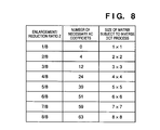
- FIG. 8 An example of a table held in the DCT matrix selector 16 in Fig. 1 is shown in Fig. 8.
- the DCT matrix selector 16 has a table whose components are "numbers of necessary DCT coefficients" and "sizes of matrixes to be applied with the inverse DCT process" for each of eight ratios Z from 1/8 to 8/8. Then the number of necessary DCT coefficients is converted to the ACend signal 17 and the size of a matrix to be applied with the inverse DCT process is converted to a DCT matrix signal 18, and signals are sent to the Huffman decoding unit 11 and the inverse DCT converter 12, respectively.
- Huffman decoding process is continuously operated until the end of a block (EOB) code indicating the end of a single block of coded data is detected or all 64 coded data are decoded.
- EOB block
- Fig. 9 is a block diagram illustrating a configuration of coding and display process in an image processing apparatus according to the second embodiment.
- the elements which are the same or similar to the elements in Fig. 1 are referred by the same reference numerals as in Fig. 1, and the description of these elements are omitted.
- reference numeral 90 denotes a coded data skip controller
- reference numeral 91 denotes a skip information memory.
- the coded data skip controller 90 instructs to move a coded data pointer stored in the image memory A 10 in accordance with a code length per block which is stored in the skip information memory 91 in advance, that will be described later, when a signal indicating that the least necessary DCT coefficients have been decoded from the Huffman decoding unit 11.
- coded data of the N-th block consists of a DC component 101 of Huffman code followed by a DC component additional bit 102, a first AC component 103 of Huffman code, and an additional bit 104 of the first AC component.
- coded data a plurality of AC components and of additional bits of the AC components, where the maximum number is 63, can exist until the EOB code 110 is placed at the end of the block of coded data.
- a N-th block is consists of bits referred as 101 to 110 then a (N + 1)-th block follows.
- Length of the coded data can change since it is a Huffman code, further, the number of AC components in the coded data differs depending upon a block. Therefore, the block length of the N-th block and the block length of the (N + 1)-th block differ from each other, thus it is not possible to predict a top position of the (N + 1)-th block in the middle of decoding process of the N-block.
- block length of each block are checked in advance, and the difference between a block lengths of the current block and of the previous block is found, and the obtained difference is coded and stored in the skip information memory 91. And during performing of Huffman decoding, a block length of a single block is found on the basis of the coded data on the difference stored in the skip information memory 91, and a skip amount of the coded data stored in the image memory A 10 is controlled by the coded data skip controller 90.
- step S90 position pointers of the previous block CP_OLD and a block length of the previous block BP_OLD are reset. Then, a current block is decoded at step S91.
- step S92 a block length of the current block BP is obtained from the difference between a pointer of code position in the current block CP, and the pointer of position in the previous block CP_OLD.
- step S93 the difference between the block length of the previous block BP_OLD and the block length of the current block BP is find, and the obtained difference is coded based on Huffman coding.
- step S94 CP_OLD and BP_OLD are updated by being replaced by CP and BP, respectively.
- step S95 whether or not all the differences between two succeeding blocks are encoded is determined, and if not, the process goes back to step S91 and the next block is processed.
- block lengths to be stored in the skip information memory 91 are coded in the second embodiment.
- the coded differences in block lengths are decoded in the inverse process to the one shown in Fig. 11, and a skip amount while coded data is read can be determined by referring to the decoded differences in the second embodiment.
- a pointer k indicating the position of a last DCT coefficient decoded is initialized to "0"
- the block of coded data is read in accordance with the pointer indicating the position of the coded data.
- first decoding of an AC component designated by the pointer k is performed by using a Huffman coding table (not shown) for AC components.
- the zero run length (zr) and the group number (gr) are determined from the first decoded value of the AC component obtained at step S1103 by using the Huffman coding table for AC components.
- EOB block code
- step S1107 an additional bit is read.
- the AC component is determined from a grouping table for AC components (not shown), successively the position of the last DCT coefficient which has been already processed is updated by adding zr + 1 to the pointer k at step S1109.
- step S1110 whether or not the pointer k indicating the position of the last DCT coefficient which has been processed is less than a necessary DCT coefficient number, ACend, which is a threshold, is checked. If the pointer k is less than the ACend, the process proceeds to step S1111, whereas, if the pointer k is greater or equal to the ACend, the process moves to step S1112.
- a pointer indicating a position of a last coefficient which has been decoded is incremented until the pointer designates the top of the next block by referring to each block length information stored in the skip information memory 92 in Fig. 9, then the position of coded data to be read next is skipped thereby completing the process.
- step S1111 whether the pointer k indicating a position of the last coefficient which has been already processed is less than 64, a maximum value, is determined. In a case where the pointer k is greater or equal to 64, coding process is completed. Whereas, if the pointer k is less than 64, the process goes back to step S1102, and decoding process of the next AC component starts.
- the pointer indicates to skip the next block without processing the rest of AC components in the current block. Therefore, it is possible to shorten a processing time of decoding process by omitting operations on unnecessary AC components.
- filtering is performed on coded data in advance and the coded data is stored after the block is converted to a block of fixed length.
- Fig. 13 shows a block diagram illustrating an example of configuration of decoding/display unit in an image processing apparatus according to the third embodiment.
- the elements which are the same or similar to the consisting in Fig. 9 in the second embodiment are referred with the same reference numerals as in Fig. 9, and the description of these elements are omitted.
- reference numeral 1301 denotes an image memory controller which filters coded data as described above.
- Fig. 14 shows an example of a work area in a case where a single block of coded data is stored in fixed length according to the third embodiment.
- a fixed block length N which is smaller than a maximum block length of coded data and has a bit number of a multiple of 8 is decided in advance, and a block of coded data 1401 fills the work area of the fixed block length N from the top. Accordingly, the rest of the work area of the fixed block length N, 1402, becomes an area for adjustment, and contents to fill the area is not decided.
- a code to indicate the beginning of an area for adjustment in advance for instance, the area becomes invalid during decoding AC components by the Huffman decoding unit 11 in Fig. 13.
- Fig. 15 is a flowchart illustrating a process in the image memory controller 1301 shown in Fig. 13.
- step S1200 coded data is read.
- step S1201 an EOB code indicating the end of a block of coded data is checked. Thereby a block of coded data is checked.
- step S1202 a block length of coded data is adjusted by using the work area shown in Fig. 14. The coded data block which has its length adjusted so as to fit the fixed length is recorded in the image memory A 10 in Fig. 13. at step S1203.
- processing time can be further shortened since it is easier to skip unnecessary coded data during decoding AC components by fixing the block length of coded data.
- the skip information memory 91 in Fig. 13 is not always necessary in the third embodiment, however, it can be used to store information on fixed block length, for instance.
- the predetermined fixed block length of the third embodiment is preferably determined experimentally for each image processing apparatus, since the most suitable block length differs depending upon the compression ratio, configuration of memory, and so on, of the apparatus.
- decoding time is shortened by removing redundancy of a code which will be generated by an encoder.
- a ZRL code is used to represent sixteen zeros, and the ZRL code is repeatedly used until the zero run length becomes shorter than 15.
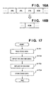
- An example where a plurality of ZRL codes are used in coded data is shown in Fig. 16A.
- the DCT coefficients of high frequency in a coded data block for example, most of coefficients which are placed in relatively latter in Fig. 5, are zero, it is preferred to attach the EOB code after the last coefficient having some value other than zero (significant coefficient).
- the ZRL codes are also decoded during decoding process, which consumes some time.
- a construction of an apparatus in the fourth embodiment is similar to that shown in the third embodiment with reference to Fig. 13, however filtering process by the image memory controller 1301 in Fig. 13 differs.
- Fig. 17 is a flowchart illustrating a process by the image memory controller 1301 in Fig. 13 in the fourth embodiment.
- a coded data is read, then at step S1702, a ZRL code indicating zero run length of sixteen and an EOB code indicating the end of a block of coded data are detected.
- step S1703 in only a case where at least a single ZRL code is followed by the EOB code, these codes are replaced by a single EOB code.
- a coded data block in which the ZRL code, followed by the EOB code, is deleted is stored in the image memory A 10 in Fig. 13 at step S1704.
- processing time for decoding is further shortened by storing coded data after deleting redundancy, produced while image data is encoded, since it is not necessary to perform decoding on unnecessary ZRL codes during decoding of AC components.
- the final image output unit is a display according to the constitution of the image processing apparatus, however, the present invention is not limited to this, and any kinds of output apparatus can be used as long as the apparatus is able to output an image.
- a printing unit such as a printer, a transmission apparatus, such as a facsimile, or the like, can be used.
- sizes of an image obtained by decoding coded data by employing the hierarchical coding method are predetermined sizes, such as 1/2 ⁇ 1/2 and 1/4 ⁇ 1/4 of an original image, which are decided during encoding process. Therefore, it is difficult to apply the hierarchical coding method when an original image needs to be changed to an image of an arbitrary size.
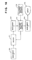
- Fig. 18 is a block diagram illustrating a constitution of a unit, performing decoding and display, of an image processing apparatus according to the fifth embodiment of the present invention.
- reference numeral 210 denotes an image memory A which stores DCT coded data, more particularly, by ADCT defined in JPEG.
- the coded data is sent from the image memory A 210 to a decoder 211 where the coded data is decoded in accordance with a DCT matrix which is outputted from an enlargement/reduction controller 213 (referred as "controller 213", hereinafter) that will be described later.
- controller 213 enlargement/reduction controller
- the controller 213 outputs the DCT matrix to the decoder 211 in accordance with an enlargement/reduction ratio Z (referred as "ratio Z”, hereinafter) which is designated by an enlargement/reduction ratio designator 216 (referred as “ratio designator”, hereinafter). Further the controller 213 changes sizes of the decoded image data stored in the image memory B 212 by using known methods, such as a sub-sampling and interpolation method, and the processed image data is stored in an image memory C 214. The image data stored in the image memory C 214 is displayed on a display 215, such as a monitor.
- the display 215 can be replaced by any device, such as a printing device, as long as it is possible to output image data representing an image whose size is changed.
- a proper hierarchy of coded data encoded by using the hierarchical coding method is decoded, then corrected in accordance with to the designated enlargement/reduction ratio.
- the ratio Z is designated by the ratio designator 216 shown in Fig. 18, then at step S271, the hierarchy of the hierarchy coding method is decided based on the ratio Z at the controller 213.
- the maximum n (n ⁇ 8; n is a positive integer) is decided so that n/8 does not exceed the ratio Z as a hierarchy of the hierarchical coding method.
- step S272 whether or not decoding of image data to the size of n/8 ⁇ n/8 has been already completed is checked by determining whether or not any decoded data exists in the image memory B 212, for instance. With the determination at step S272, image data which has already been decoded is not applied with another decoding process, and can be changed to a size corresponding to a enlargement/reduction ratio between n/8 and (n+1)/8.
- step S272 If image data is determined to have been decoded already at step S272, the process proceeds to step S275, while if not, the process moves to step S273.
- n/8 ⁇ n/8 size decoded data is generated by using inverse transfer using a n ⁇ n matrix in the decoder 211, and outputted to an image memory B 212.
- known enlargement method such as interpolation processing, is applied to the decoded n/8 ⁇ n/8 size image stored in the image memory B 212 in the controller 213, so that the reduced size is changed to a size designated by the ratio Z at step S270, and the processed image data is outputted to the image memory C 214.
- the image data is displayed on the display 215.
- completion of displaying an image whose size is changed is checked.
- step S277 in a case where it is unnecessary to continue the process to change sizes, the entire process is terminated, whereas in a case where a different enlargement/reduction ratio is to be newly designated, the process goes back to step S270, and the new ratio is designated.
- display process at step S276 can be other process, such as printing process by a printer, as long as an image whose size is changed can be outputted.
- n is decided so that it satisfies a n/8 ⁇ Z condition at step S271 in Fig. 19, therefore, the possible value of n is limited to the range between 1 and 8.
- the range which the ratio Z can take is limited to 1/8 ⁇ Z, and it is not possible to reduce an image to a size smaller than 1/8.
- decoding process to decode the DC component of hierarchically coded (DCT) data by the decoder 211 shown in Fig. 18 is the same as the process described in the aforesaid first embodiment with reference to Fig. 2, thus the explanation of the process is omitted.
- Fig. 20 is a flowchart illustrating decoding process of AC components of the decoding process of the DCT coded data by the decoder 211 shown in Fig. 18.
- a pointer k indicating a position of a decoded DCT coefficient is reset.
- a coded data block is read, and at step S232, a first decoding process is applied on an AC component which is designated by the pointer k by using a Huffman table for AC components (not shown).
- EOB end of block
- step S237 additional bits are read.
- step S2308 AC components are determined in accordance with a grouping table for AC components (not shown).
- step S239 by adding zr + 1 to the pointer k, data on a position of a last DCT coefficient which has been already processed is updated. Then the process proceeds to step S242 where whether or not the pointer indicating the last DCT coefficient which has been already processed is less than 64 is checked. If not, the decoding of the block is completed.
- step S231 decoding process of a next AC component starts.
- the decoding process of AC components in the fifth embodiment is performed.
- the decoding by the decoder 211 shown in Fig. 18 includes reduction of a size of an image during applying the inverse DCT process on the DCT coefficients, as in the case described in the first embodiment with reference to Figs. 5 to 7.
- each ratio Z from 1/8 to 8/8, designated by the ratio designator 216 corresponds to each of the size of the matrix subjected to inverse DCT process.
- the controller 213 outputs a matrix to be used for an inverse DCT process to the decoder 211.
- the decoder 211 find DCT coefficients of coded data to be decoded by referring the DCT matrix outputted from the controller 213.
- the processing time is shortened without using a memory of a large capacity.
- the process to change the sizes of the image represented by decoded data at step S275 in Fig. 19 is enlargement process, thus quality of the image may be deteriorated, which may cause blur, or the like, in the image. Therefore, in the sixth embodiment, a method to decide a hierarchy n in the hierarchical coding method is changed so that decoded data is applied with reduction process.
- a constitution of an image processing apparatus in the sixth embodiment is the same as the one in Fig. 18 in the fifth embodiment.
- a hierarchy of the hierarchical coding method corresponding to the ratio Z is determined at the controller 213.
- n (n ⁇ 8; n is a positive integer), satisfying a condition (n - 1)/8 ⁇ Z ⁇ n/8, is decided. Accordingly, image data is decoded to image data representing a n/8 ⁇ n/8 size image by the decoder 211, thus the decoding process is performed to change sizes of an image corresponding to one size larger than the designated ratio Z in the sixth embodiment.
- step S281 the reduced n/8 ⁇ n/8 size decoded image, stored in the image memory B 212, is applied with reduction process, such as known sub-sampling or the like in the controller 213, so that the size of the image corresponds to the ratio Z designated at step S270.
- the processed image data is outputted to the image memory C 214. Accordingly, high frequency components of the image can be maintained, thus a reduced image of high quality can be obtained.
- n satisfying the condition (n - 1)/8 ⁇ Z ⁇ n/8 is decided, and, since the value which n can take is in a range between 1 and 8, the range which the ratio Z can take is limited to a range 0 ⁇ Z ⁇ 1. Therefore, it is not possible to change sizes corresponding the ratio Z > 1, namely enlarging process.
- an image in process to change sizes of an image represented by image data which is encoded by the hierarchical coding method, such as DCT coding, in accordance with an arbitrary ratio beside fixed sizes, more particularly in reduction process, an image can be reproduced in high quality.
- the hierarchical coding method such as DCT coding
- decoding process is performed by using both a hierarchy (n - 1) of the hierarchical coding method and subsequent enlargement and a hierarchy n and a subsequent reduction, and decoded data of two different sizes is used so that the process of changing sizes of an image after decoding image data representing the image can be either reduction or enlargement process.
- a constitution of an image processing apparatus according to the seventh embodiment is almost the same as the one in Fig. 18 described in the fifth embodiment, however, the image memory B 212 in the seventh embodiment requires larger capacity.
- Fig. 22 shows an example of an enlargement/ reduction ratio table referred when a hierarchy n of the hierarchical coding method is decided.
- the enlargement/reduction ratio table shown in Fig. 22 is stored in the controller 213 in Fig. 18.
- the range which the ratio Z can take is between 0 ⁇ Z. Accordingly, it is possible to perform process of changing size in accordance with an arbitrary enlargement/reduction ratio.
- the enlargement/reduction ratio table is not limited to the one shown in Fig. 22, but can be set so as to draw the ability of a processing apparatus to the maximum.
- a hierarchy of the hierarchical coding method corresponding to the ratio Z is determined by the controller 213 at step S2101.
- n (n ⁇ 8; n is a positive integer), satisfying a condition (n - 1)/8 ⁇ Z ⁇ n/8, is decided.
- step S2102 whether or not (n - 1)/8 size decoded data exists is checked by, for example, checking whether or not (n - 1)/8 size decoded data exists in the image memory B 212.
- step S 2102 if image data is decoded to the (n - 1)/8 size, the process moves to step S2104, whereas if not, the process proceeds to step S2103.
- (n - 1)/8 size decoded data is generated by inverse DCT process using a (n - 1) ⁇ (n - 1) matrix in the decoder 211, and outputted to the image memory B 212.
- step S2104 whether or not n/8 ⁇ n/8 size decoded data exist is checked by, for example, checking whether or not n/8 ⁇ n/8 size decoded data exists in the image memory B 212.
- step S2104 if the image data is decoded to the n/8 ⁇ n/8 size, the process moves to step S2106, whereas if not, the process proceeds to step S2105.
- step S2105 n/8 ⁇ n/8 size decoded data is generated by inverse DCT process using a n ⁇ n matrix in the decoder 211, and outputted to the image memory B 212.
- step S2106 by referring the enlargement/ reduction designation table shown in Fig. 22, it is decided whether reduction process is applied to the decoded n/8 ⁇ n/8 size image data or enlargement process is applied to the decoded (n - 1)/8 ⁇ (n - 1)/8 image data, then the decided decoded image data is stored in the image memory B 212.
- step S2107 by following the processing order decided at step S2106, reduction or enlargement process, such as known sub-sampling and interpolation process, is applied on image data by the controller 213 so that the changed size corresponds to the ratio Z designated at step S270.
- the processed image data is outputted to the image memory C 214.
- the processing time is reduced as well as quality of the reproduced image is improved without using a memory of large capacity.
- the image memory B 212 since decoded data of two different sizes have to be stored in the image memory B 212, the image memory B 212 requires large capacity, and redundant processes, such as decoding image data into two kinds of image data of two different sizes, are included.
- the number of image data to be decoded is one.
- decoded data to be used is determined from the (n - 1)/8 ⁇ (n - 1)/8 size decoded data and the n/8 ⁇ n/8 size decoded data by referring to the enlargement reduction designation table at step S2106.
- the size of the image to which image data is decoded is reduced to one size.
- a structure of an image processing apparatus according to the eighth embodiment is the same as the one shown in Fig. 18 in the aforesaid fifth embodiment.
- a hierarchy n of the hierarchical coding method is decided by taking a numerator of a fraction in a row where the ratio Z belongs in a column of "designation of process" in the enlargement/reduction designation table in Fig. 22.
- the steps S273 and S274, following step S290, is the same as described with reference to Fig. 19 in the fifth embodiment, namely, image data is decoded to a n/8 ⁇ n/8 size.
- the reduced n/8 ⁇ n/8 size decoded image data, stored in the image memory B 212 is applied with reduction or enlargement process, such as known sub-sampling and interpolation process, by the controller 213 in accordance with designated contents in the enlargement/reduction designation table referred at step S290, so that the reduced size becomes the same as the ratio Z designated at step S290.
- the processed image data is outputted to the image memory C 214.
- the processing time is further shortened and the quality of the reproduced image is further improved.
- the aforesaid process can draw the same or similar effects when the process of decoding and changing sizes is performed by using software.
- Fig. 25 is a block diagram of a constitution of a hierarchical processing unit which converts sequential coded data into hierarchical coded data in an image processing apparatus in a ninth embodiment.
- coded data converted to DCT sequential coded data is inputted by an input unit 311, such as a communication line.
- an input unit 311 such as a communication line.
- the inputted DCT sequential coded data is processed with Huffman coding and inverse-quantizing to reproduce a 8 ⁇ 8 DCT coefficient matrix. Then the obtained 8 ⁇ 8 DCT coefficient matrix is stored in a DCT coefficient memory A 313.
- the DCT coefficients stored in the DCT coefficient memory A 313 are inputted to a DC component selector 314, a 2 ⁇ 2 selector 315, a 4 ⁇ 4 selector 316, and an 8 ⁇ 8 selector 317.
- the DC component selector 314 the DC component is extracted from the inputted DCT coefficients, and quantized and coded by a DPCM encoding unit 318, then stored in a hierarchical code memory 322.
- the hierarchical code memory 322 can be a semi-conductor memory or a secondary memory, such as a hard disk, and the required capacity of the memory is much smaller than capacity of a memory for storing entirely decoded input data as pixel image data.
- a 2 ⁇ 2 coefficient matrix is selected out of the 8 ⁇ 8 DCT coefficient matrix inputted from the DCT coefficient memory A 313, and after quantized and Huffman encoded by an AC encoding unit A 319, stored in a hierarchical code memory 322. In short, 1/4 ⁇ 1/4 size coded data is generated.
- the 4 ⁇ 4 selector 316 selects a 4 ⁇ 4 coefficient matrix out of the 8 ⁇ 8 DCT coefficient matrix inputted from the DCT coefficient memory A 313, and after quantized and Huffman encoded by an AC encoding unit B 320, the obtained data is stored in a hierarchical code memory 322. Namely, 1/2 ⁇ 1/2 size coded data is generated.
- a 8 ⁇ 8 coefficient matrix is selected out of the 8 ⁇ 8 DCT coefficient matrix inputted from the DCT coefficient memory A 313, and after quantized and Huffman encoded by an AC encoding unit C 321, stored in the hierarchical code memory 322. Therefore, the entire size coded data is generated.
- zigzag scanning which is a method of selecting DCT coefficients at each DCT coefficient selector, such as the DC component selector 314 to the 8 ⁇ 8 selector 317, will be explained.
- Fig. 26A shows an ordinary order to zigzag-scan 8 ⁇ 8 DCT coefficients. Further, Fig. 26B shows a position of a DC component of the 8 ⁇ 8 DCT coefficients.
- a DC component is extracted by the DC component selector 314 in Fig. 25 to form a 1/8 ⁇ 1/8 size image, and quantized and encoded by the DPCM encoding unit 318.
- Fig. 26C shows an order of 2 ⁇ 2 zigzag scanning out of the 8 ⁇ 8 DCT coefficients at the AC encoding unit A 319 in Fig. 25, and three coefficients excluding the DC component and the previously encoded DCT coefficients are Huffman encoded in the shown order.
- Fig. 26D shows an order of 4 ⁇ 4 zigzag scanning out of the 8 ⁇ 8 DCT coefficients at the AC encoding unit B 320 in Fig. 25, and twelve coefficients excluding the DC component are Huffman encoded in the shown order.
- Fig. 26E shows an order of 8 ⁇ 8 zigzag scanning out of the 8 ⁇ 8 DCT coefficients at the AC encoding unit C 321 in Fig. 25, and forty-eight coefficients excluding the DC component and the fifteen previously encoded DCT coefficients are Huffman encoded in the shown order.
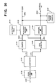
- Fig. 27 is a block diagram illustrating a constitution of a display for displaying the hierarchical coded data.
- the hierarchical code memory 322 has the same construction as in Fig. 25, and it stores the hierarchical coded data generated by the hierarchical encoding unit described with reference to Fig. 25.
- a DPCM decoding unit 323 decodes and inverse-quantizes the coded data which is encoded by the DPCM encoding unit 318 shown in Fig. 25. Accordingly, only the DC component out of the 8 ⁇ 8 DCT coefficients is decoded, then applied with inverse DCT process at an inverse DCT unit A 327, thus 1/8 ⁇ 1/8 size YUV image data is obtained.
- the 1/8 ⁇ 1/8 size YUV image data is converted into RGB image data at a color converter A 331, and the RGB image data is stored in an output image memory A 335 as 1/8 ⁇ 1/8 size image data.
- An AC decoding unit A 324 decodes and inverse-quantizes the coded data which is encoded by the AC encoding unit A 319 shown in Fig. 25. Accordingly, a 2 ⁇ 2 coefficient matrix out of 8 ⁇ 8 DCT coefficients is obtained. It is applied with inverse DCT process at an inverse DCT unit B 328, thus 1/4 ⁇ 1/4 size YUV image data is obtained. The 1/4 ⁇ 1/4 size YUV image data is converted into RGB image data at a color converter B 332, and the RGB image data is stored in an output image memory B 336 as 1/4 ⁇ 1/4 size image data.
- An AC decoding unit B 325 decodes and inverse-quantizes the coded data which is encoded by the AC encoding unit B 320 shown in Fig. 25. Accordingly, a 4 ⁇ 4 coefficient matrix out of 8 ⁇ 8 DCT coefficients is obtained. It is applied with inverse DCT process at an inverse DCT unit C 329, thus 1/2 ⁇ 1/2 size YUV image data is obtained.
- the 1/2 ⁇ 1/2 size YUV image data is converted into RGB image data at a color converter C 333, and the RGB image data is stored in an output image memory C 337 as 1/2 ⁇ 1/2 size image data.
- An AC decoding unit C 326 decodes and inverse-quantizes the coded data which is encoded by the AC encoding unit C 321 shown in Fig. 25. Accordingly, an 8 ⁇ 8 coefficient matrix is obtained. It is applied with inverse DCT process at an inverse DCT unit D 330, thus full size YUV image data is obtained. The full size YUV image data is converted into RGB image data at a color converter B 332, and the RGB image data is stored in an output image memory C 338 as full size image data.
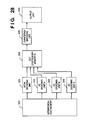
- Fig. 28 is a block diagram illustrating a constitution of a sequential coding unit which converts the hierarchical coded data into the sequential coded data.
- the same elements as in Fig. 27 have the same reference numerals, and their explanations are omitted.
- the hierarchical coded data store in the hierarchical code memory 322 is reproduced to DCT coefficients by being decoded and inverse-quantized by the DPCM decoding unit 323, the AC decoding unit A 324, the AC decoding unit B 325, and the AC decoding unit C 326, and further reconstructed into 8 ⁇ 8 DCT coefficients in a DCT coefficient memory B 338. Then, the reconstructed 8 ⁇ 8 DCT coefficients are quantized by a quantizing/encoding unit 339, further Huffman coded. The processed coefficients are outputted to an output unit 340, such as a communication line and a storage device, as sequential DCT coded data. It should be noted that the order of zigzag scanning of the 8 ⁇ 8 DCT coefficients in the quantizing/encoding unit 339 is the same as in Fig. 26A.
- the sequential coded data outputted to the output unit 340 in Fig. 28 is identical to the sequential coded data inputted from the input unit 311 in Fig. 25.
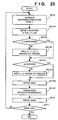
- Fig. 29 is a block diagram illustrating a detailed constitution of a Huffman encoding unit for a DC component in the DPCM encoding unit 318 in Fig. 25.
- DC component data 3200 quantized by a quantizing unit (not shown) in the DPCM encoding unit 318 in Fig. 25 is inputted to a subtractor 3120, where subtraction process is applied to the DC component and the output 3209, data of one block previous, from a delay unit 3121, then the difference data 3201 is outputted.
- the difference data 3201 is inputted to a level detector 3122 and an additional bit generator 3213.
- the level detector 3122 divide the difference data 3201 into groups depending on its level, and output the group referred as 3202 into the DC Huffman encoding unit 3124.
- a code 3204 corresponding to the inputted group number is decided with reference to the DC Huffman table 3125, and outputted.
- the additional bit generator 3123 there is generated a discrimination signal which indicates a predetermined level of the group on the basis of the group 3202 and the difference data 3201, and the signal is outputted as an additional bit 3205. Further, the code 3204 and the additional bit 3205 are inputted to a DC code length counter 3126, and their code lengths are counted.
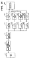
- Fig. 30 is a block diagram illustrating a detailed constitution of a Huffman encoding unit for AC components in the AC encoding unit A319, B320, and C 321.
- AC component data 3250 quantized by a quantizing unit (not shown) of the AC encoding units A 319, B 320, and C 321 in Fig. 25 is inputted to a zigzag scanning unit 3130, where the AC components are scanned in the order shown in Figs. 26A to 26E.
- the scanned coefficients are outputted to a comparator 3131.
- the comparator 3131 determines whether or not the inputted AC component is "0". If the AC component is determined as "0" in the comparator 3131, a counter 3132 counts up, and the counted number is outputted to an AC Huffman encoding unit 3133 as a zero run length. Whereas, if the AC component is not "0", then the level of the AC component is divided into groups at a level detector 3135, and a group 3251 is outputted to the AC Huffman encoding unit 3133 and an additional bit generator 3136.
- a code 3253 corresponding to the group 3251 inputted from the level detector 3135 and the count number of zeros which is inputted from the counter 3132, is decided with reference to the code table of an AC Huffman table 3134 and outputted.
- the additional bit generator 3136 there is generated a discrimination signal indicating a predetermined level of the group shown in the group 3251 inputted from the level detector 3135, and the signal is outputted as an additional bit 3254. Furthermore, the code 3253 and the additional bit 3254 are counted their code lengths by an AC code length counter 3137.
- the hierarchical coding process of four hierarchies namely, a DC component, 2 ⁇ 2 DCT coefficients, 4 ⁇ 4 DCT coefficients, and 8 ⁇ 8 DCT coefficients is performed.
- sequential data is the data for final output, such as printing, it is stored unprocessed, and a case where data of three hierarchies, DC, 2 ⁇ 2 DCT, and 4 ⁇ 4 DCT is generated as sub-information is described with reference to Fig. 31.
- Fig. 31 is a block diagram illustrating a constitution of the hierarchical coding unit which converts sequential coded data into hierarchical coded data in an image processing apparatus according to the tenth embodiment.
- a signal 700 inputted from the input unit 31 is sequential coded data, and directly stored in the hierarchical code memory 322. Beside the signal 700, data which is stored in the hierarchical code memory 322 is DC, 2 ⁇ 2 DCT, and 4 ⁇ 4 DCT coded data. 8 ⁇ 8 DCT coded data is not generated in the tenth embodiment.
- th amount of hierarchical coded data to be stored in the hierarchical code memory 322 is larger than the amount in the ninth embodiment, however, the sequential coding process shown in Fig. 28 in the ninth embodiment becomes unnecessary during outputting an image to a device, such as a printer, which uses sequential image data, thus the unprocessed sequential coded data of the signal 700 can be outputted from the hierarchical code memory 322. Accordingly, the size of an apparatus can be minimized as well as the processing time can be shortened.
- a configuration of a hierarchical encoding unit according to the eleventh embodiment is realized by changing a method of selecting a DC component selected in the DC component selector 314 in Fig. 25 in the aforesaid ninth embodiment.
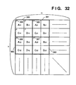
- FIG. 32 A construction of a plurality of 8 ⁇ 8 DCT coefficient blocks according to the eleventh embodiment is shown in Fig. 32.
- reference numeral 380 denotes a set of sub-block which is composed of four 8 ⁇ 8 DCT coefficient blocks, A11, B11, C11, and D11.
- reference numerals 381, 382, and 383 denotes sub-blocks each of which is composed of four 8 ⁇ 8 DCT coefficient blocks.
- all the DCT coefficient block is divided into n ⁇ m sub-blocks.
- a DC component 384 in a left upper block A11 of a sub-block 380 and a DC component 385 in a block A21 of a sub-block 381, and a DC component 386 in a block A12 of a sub-block 383, and a DC component 387 in a block A22 of a sub-block are applied with DPCM encoding process in the DPCM encoding unit 318 in Fig. 25, then stored in the hierarchical code memory 322. Accordingly, the stored data is the 1/16 ⁇ 1/16 hierarchical coded data.
- DC components are extracted from each block, B11, C11, and D11 in the sub-block 380, for instance, and the differences between these DC components and the DC component 384 of All are applied with the DPCM encoding process in the DPCM encoding unit 318, then stored in the hierarchical code memory 322. The similar process is applied to all other sub-blocks.
- the method to obtain 1/8 ⁇ 1/8 size hierarchical coded data is not limited to the method described above, but can be a method of extracting each DC component from block B21, C21, D21 in the sub-block 381 and applying DPCM encoding process to the differences between the extracted DC components and each DC components of B11, C11, and D11 in the previous sub-block 380, for instance.
- Fig. 32 four DCT coefficient blocks construct a single sub-block, however, the number of block to construct can be altered. For example, assuming that sixteen DCT coefficient blocks compose a single sub-block and the same process as described above is performed, 1/32 ⁇ 1/32 size hierarchical coded data can be obtained. Similarly, it is possible to reduce the size of an image to 1/64 ⁇ 1/64, 1/128 ⁇ 1/128, and so on.
- the image processing method and apparatus according to the first to eleventh embodiment is applicable not only to processing of a still picture but also a moving picture.
- the aforesaid hierarchical encoding can be applied to each frame or each field constructing a moving picture.
- the image memory A10, A20 and the input unit 311 can be provided with coded data from a host computer, a communication line, or the like. Further, the coded data can be data stored in recording medium, such as a magneto-optical disk and CD-ROM.
- the coded data is based on color image data by (Y, Cr, Cb) and (L*, a*, b*) notation, the aforesaid process can be performed on each color component.
- coded data is not limited to DCT data, but can be any kind of data as long as it is converted based on orthogonal conversion.
- the present invention can be applied to a system constituted by a plurality of devices, or to an apparatus comprising a single device. Furthermore, the invention is applicable also to a case where the object of the invention is attained by supplying a program to a system or apparatus.
Claims (12)
- Bildverarbeitungsverfahren unter Verwendung einer Bildverarbeitungseinrichtung, die codierte Bilddaten, die durch ein hierarchisches Codierverfahren in (NxN)-Blockeinheiten (wobei N eine positive ganze Zahl ist) codiert worden sind, decodiert und decodierte Bilddaten ausgibt, mit:einem Verhältniseinstellschritt zum Einstellen eines Vergrößerungs-/Verkleinerungsverhältnisses Z zwischen dem codierten Bild und dem auszugebenden decodierten Bild;einem Hierarchieeinstellschritt zum Einstellen einer Hierarchie n, wobei n eine positive ganze Zahl ist, derart, daß n/N dem Verhältnis Z, das bei dem Verhältniseinstellschritt gesetzt wird, am nächsten wird, wobei n ≤ N gilt;einem Decodierschritt zum Decodieren der codierten Bilddaten in Daten von einer Größe n/N x n/N, auf der Grundlage der bei dem Hierarchieeinstellschritt gesetzten Hierarchie n; und miteinem Vergrößerungs-/Verkleinerungsschritt zum Ändern der Größe der Bilddaten, die bei dem Decodierschritt decodiert werden, um dem bei dem Verhältniseinstellschritt gesetzten Verhältnis Z zu entsprechen.
- Verfahren nach Anspruch 1,
dadurch gekennzeichnet, daß
die codierten Bilddaten durch ein DCT(Diskrete Kosinustransformation)-Codierverfahren codiert werden, und daß n x n DCT-Koeffizienten decodiert und bei einer umgekehrten DCT bei dem Decodierschritt angewendet werden. - Verfahren nach Anspruch 1 oder 2,
dadurch gekennzeichnet, daß
das gesetzte n bei einer Hierarchie die größte Zahl unter positiven ganzen Zahlen ist, die die Bedingung n/N < Z bei dem Hierarchieeinstellschritt erfüllt. - Verfahren nach einem von Ansprüchen 1 oder 2,
dadurch gekennzeichnet, daß
bei dem Hierarchieeinstellschritt das gesetzte n bei einer Hierarchie die Bedingung (n-1)/N < Z < n/N erfüllt. - Verfahren nach Anspruch 4,
dadurch gekennzeichnet, daß
die codierten Bilddaten bei dem Decodierschritt in Daten von zwei Größen, nämlich einer Größe (n-1)/N x (n-1)/N und einer Größe n/N x n/N decodiert werden, und daß die decodierten Daten, deren Größe dem Verhältnis Z näher ist, aus den decodierten Daten mit den zwei Größen, die bei dem Decodierschritt decodiert werden, bei dem Vergrößerungs-/Verkleinerungsschritt in der Größe weiter geändert werden. - Verfahren nach einem vorangehenden Anspruch,
dadurch gekennzeichnet, daß
die Hierarchie n unter Bezugnahme auf eine Vergrößerungs-/Verkleinerungsbestimmungstabelle, die ein Verfahren zur Vergrößerung/Verkleinerung auf der Grundlage des Verhältnisses Z bestimmt, bei dem Hierarchieeinstellschritt gesetzt wird. - Bildverarbeitungseinrichtung zum Decodieren und Ausgeben von codierten Bilddaten, die durch ein hierarchisches Codierverfahren in (NxN)-Blockeinheiten codiert sind, wobei N eine positive ganze Zahl ist, mit:einer Verhältniseinstelleinrichtung (216) zum Einstellen eines Vergrößerungs-/Verkleinerungsverhältnisses Z;einer Hierarchieeinstelleinrichtung (213) zum Einstellen einer Hierarchie n, wobei n eine positive ganze Zahl ist, derart, daß n/N dem durch die Verhältniseinstelleinrichtung gesetzten Verhältnis Z am nächsten wird, wobei n ≤ N gilt;einer Decodiereinrichtung (211) zum Decodieren der codierten Bilddaten in Daten von einer Größe n/N x n/N auf der Grundlage der durch die Hierarchieeinstelleinrichtung gesetzten Hierarchie n;einer Vergrößerungs-/Verkleinerungseinrichtung (213) zum Ändern von Größen der durch die Decodiereinrichtung decodierten Bilddaten, um dem durch die Verhältniseinstelleinrichtung gesetzten Verhältnis Z zu entsprechen.
- Einrichtung nach Anspruch 7,
dadurch gekennzeichnet, daß
die codierten Bilddaten durch das DCT-Codierverfahren codiert wurden, und daß die Decodiereinrichtung angepaßt ist, um n x n DCT-Koeffizienten zu decodieren und eine umgekehrte DCT anzuwenden. - Einrichtung nach Anspruch 7 oder 8,
dadurch gekennzeichnet, daß
die Hierarchieeinstelleinrichtung n bei einer Hierarchie auf eine größte Zahl unter positiven ganzen Zahlen, die die Bedingung n/N < Z erfüllt, setzt. - Einrichtung nach Anspruch 7 oder 8,
dadurch gekennzeichnet, daß
die Hierarchieeinstelleinrichtung n bei einer Hierarchie, die die Bedingung (n-1)/N < Z < n/N erfüllt, setzt. - Einrichtung nach Anspruch 10,
dadurch gekennzeichnet, daß
die Decodiereinrichtung angepaßt ist, um die codierten Bilddaten in Daten von zwei Größen, nämlich eine Größe (n-1)/N x (n-1)/N und eine Größe n/N x n/N, zu decodieren, und daß die Vergrößerungs-/Verkleinerungseinrichtung angepaßt ist, um eine Größe der decodierten Daten, deren Größe dem Verhältnis Z näher ist, aus den decodierten Daten von den zwei Sätzen von Daten, die durch die Decodiereinrichtung decodiert sind, weiter zu ändern. - Einrichtung nach einem der Ansprüche 7 bis 11,
dadurch gekennzeichnet, daß
die Hierarchieeinstelleinrichtung die Hierarchie n unter Bezugnahme auf eine Vergrößerungs-/Verkleinerungsbestimmungstabelle, die ein Verfahren zur Vergrößerung/Verkleinerung, auf der Grundlage des Verhältnisses Z bestimmt, setzt.
Applications Claiming Priority (9)
| Application Number | Priority Date | Filing Date | Title |
|---|---|---|---|
| JP1065594 | 1994-02-01 | ||
| JP10655/94 | 1994-02-01 | ||
| JP1065694A JPH07222150A (ja) | 1994-02-01 | 1994-02-01 | 画像処理方法及び装置 |
| JP1065594A JPH07222149A (ja) | 1994-02-01 | 1994-02-01 | 画像処理方法及び装置 |
| JP10657/94 | 1994-02-01 | ||
| JP1065694 | 1994-02-01 | ||
| JP10656/94 | 1994-02-01 | ||
| JP1065794 | 1994-02-01 | ||
| JP1065794A JPH07222151A (ja) | 1994-02-01 | 1994-02-01 | 画像処理方法及び装置 |
Publications (3)
| Publication Number | Publication Date |
|---|---|
| EP0665512A2 EP0665512A2 (de) | 1995-08-02 |
| EP0665512A3 EP0665512A3 (de) | 1996-03-06 |
| EP0665512B1 true EP0665512B1 (de) | 2000-05-10 |
Family
ID=27279042
Family Applications (1)
| Application Number | Title | Priority Date | Filing Date |
|---|---|---|---|
| EP95300591A Expired - Lifetime EP0665512B1 (de) | 1994-02-01 | 1995-01-31 | Bildverarbeitungsverfahren und -gerät |
Country Status (3)
| Country | Link |
|---|---|
| US (1) | US5875039A (de) |
| EP (1) | EP0665512B1 (de) |
| DE (1) | DE69516734T2 (de) |
Families Citing this family (28)
| Publication number | Priority date | Publication date | Assignee | Title |
|---|---|---|---|---|
| US5845015A (en) | 1995-10-12 | 1998-12-01 | Sarnoff Corporation | Method and apparatus for resizing images using the discrete cosine transform |
| US6360018B1 (en) * | 1996-04-10 | 2002-03-19 | Canon Kabushiki Kaisha | Image processing apparatus and method |
| AU718453B2 (en) * | 1996-07-17 | 2000-04-13 | Sony Corporation | Image coding and decoding using mapping coefficients corresponding to class information of pixel blocks |
| US6473533B1 (en) * | 1996-10-25 | 2002-10-29 | Fuji Xerox Co., Ltd. | Image encoding apparatus and image decoding apparatus |
| JP4086341B2 (ja) * | 1997-06-06 | 2008-05-14 | キヤノン株式会社 | 画像処理装置およびその方法 |
| US6108448A (en) * | 1997-06-12 | 2000-08-22 | International Business Machines Corporation | System and method for extracting spatially reduced image sequences in a motion compensated compressed format |
| JP3198996B2 (ja) * | 1997-08-26 | 2001-08-13 | 日本電気株式会社 | 直交変換符号化画像の画像サイズ変換方法 |
| US6072536A (en) * | 1997-10-29 | 2000-06-06 | Lucent Technologies Inc. | Method and apparatus for generating a composite image from individual compressed images |
| WO1999029112A1 (en) * | 1997-12-01 | 1999-06-10 | Matsushita Electric Industrial Co., Ltd. | Image processor, image data processor and variable length encoder/decoder |
| JP2000217112A (ja) * | 1999-01-22 | 2000-08-04 | Asahi Optical Co Ltd | 画像圧縮伸張装置および画素数増加装置 |
| US6393154B1 (en) | 1999-11-18 | 2002-05-21 | Quikcat.Com, Inc. | Method and apparatus for digital image compression using a dynamical system |
| US6778707B1 (en) * | 1999-12-17 | 2004-08-17 | Xerox Corporation | Method for decompressing JPEG files using a variable block size inverse discrete cosine transform |
| JP3603000B2 (ja) * | 2000-02-01 | 2004-12-15 | カネボウ株式会社 | ハフマン符号化装置、ハフマン符号化方法およびハフマン符号化処理プログラムを記録した記録媒体 |
| US7062098B1 (en) * | 2000-05-12 | 2006-06-13 | International Business Machines Corporation | Method and apparatus for the scaling down of data |
| US6970179B1 (en) | 2000-05-12 | 2005-11-29 | International Business Machines Corporation | Method and apparatus for the scaling up of data |
| US6807310B1 (en) * | 2000-05-23 | 2004-10-19 | The Board Of Trustees Of The University Of Illinois | Transformation of image parts in different domains to obtain resultant image size different from initial image size |
| US6670960B1 (en) | 2000-09-06 | 2003-12-30 | Koninklijke Philips Electronics N.V. | Data transfer between RGB and YCRCB color spaces for DCT interface |
| US6940523B1 (en) | 2000-11-15 | 2005-09-06 | Koninklijke Philips Electronics N.V. | On the fly data transfer between RGB and YCrCb color spaces for DCT interface |
| US7062101B2 (en) * | 2001-03-30 | 2006-06-13 | Ricoh Co., Ltd. | Method and apparatus for storing bitplanes of coefficients in a reduced size memory |
| KR100394013B1 (ko) * | 2001-06-23 | 2003-08-09 | 엘지전자 주식회사 | 비디오 스냅 영상용 변환 부호화 장치 |
| US20050190982A1 (en) * | 2003-11-28 | 2005-09-01 | Matsushita Electric Industrial Co., Ltd. | Image reducing device and image reducing method |
| EP1788796A4 (de) * | 2004-08-30 | 2010-03-24 | Fujitsu Microelectronics Ltd | Bildwiederherstellungsvorrichtung, bildwiederherstellungsverfahren und bildwiederherstellungsprogramm |
| WO2006091041A1 (en) * | 2005-02-24 | 2006-08-31 | Lg Electronics Inc. | Method for up-sampling/down-sampling data of a video block |
| FI20065754L (fi) * | 2006-11-28 | 2008-05-29 | Liquid Air Lab Gmbh | Kuvankäsittelymenetelmä |
| US20090202165A1 (en) * | 2008-02-13 | 2009-08-13 | Kabushiki Kaisha Toshiba | Image decoding method and image decoding apparatus |
| DE102009060553A1 (de) * | 2009-08-24 | 2011-03-03 | Vitaphone Gmbh | Verfahren und System zur Speicherung und Auswertung von Daten, insbesondere Vitaldaten |
| JP2013178753A (ja) * | 2012-02-01 | 2013-09-09 | Canon Inc | 画像処理装置および方法 |
| KR20150107259A (ko) * | 2014-03-13 | 2015-09-23 | 삼성전자주식회사 | 영상 처리 방법 및 이를 지원하는 전자 장치 |
Family Cites Families (12)
| Publication number | Priority date | Publication date | Assignee | Title |
|---|---|---|---|---|
| US5028995A (en) * | 1987-10-28 | 1991-07-02 | Hitachi, Ltd. | Picture signal processor, picture signal coder and picture signal interpolator |
| JP2563450B2 (ja) * | 1988-03-10 | 1996-12-11 | 松下電器産業株式会社 | ファイル用画像処理装置 |
| US5309524A (en) * | 1988-12-08 | 1994-05-03 | Canon Kabushiki Kaisha | Image reducing apparatus |
| JP2787832B2 (ja) * | 1989-06-30 | 1998-08-20 | キヤノン株式会社 | 画像縮小方法 |
| US5251254A (en) * | 1991-02-01 | 1993-10-05 | Canon Kabushiki Kaisha | Control of incoming and outgoing calls in a key system |
| JPH04297183A (ja) * | 1991-02-28 | 1992-10-21 | Mitsubishi Electric Corp | 画像符号化装置 |
| US5168375A (en) * | 1991-09-18 | 1992-12-01 | Polaroid Corporation | Image reconstruction by use of discrete cosine and related transforms |
| JPH05261982A (ja) * | 1992-03-23 | 1993-10-12 | Seiko Epson Corp | プリント装置 |
| JPH05316357A (ja) * | 1992-05-14 | 1993-11-26 | Nippon Telegr & Teleph Corp <Ntt> | 解像度変換方法 |
| JPH06125543A (ja) * | 1992-10-12 | 1994-05-06 | Toshiba Corp | 符号化装置 |
| FR2700036B1 (fr) * | 1992-11-17 | 1995-03-03 | Jean Barda | Procédé et dispositif pour le stockage et la visualisation d'image de grande dimension. |
| CA2171335A1 (en) * | 1993-11-30 | 1995-06-08 | Munib A. Wober | Coding methods and apparatus for scaling and filtering images using discrete cosine transforms |
-
1995
- 1995-01-31 DE DE69516734T patent/DE69516734T2/de not_active Expired - Lifetime
- 1995-01-31 EP EP95300591A patent/EP0665512B1/de not_active Expired - Lifetime
-
1996
- 1996-12-04 US US08/763,626 patent/US5875039A/en not_active Expired - Lifetime
Also Published As
| Publication number | Publication date |
|---|---|
| DE69516734D1 (de) | 2000-06-15 |
| EP0665512A3 (de) | 1996-03-06 |
| DE69516734T2 (de) | 2000-09-28 |
| EP0665512A2 (de) | 1995-08-02 |
| US5875039A (en) | 1999-02-23 |
Similar Documents
| Publication | Publication Date | Title |
|---|---|---|
| EP0665512B1 (de) | Bildverarbeitungsverfahren und -gerät | |
| US5228098A (en) | Adaptive spatio-temporal compression/decompression of video image signals | |
| EP1271926B1 (de) | Bildverarbeitungsverfahren und -vorrichtung und Computerprogram für Kompressionskodierung | |
| US5473704A (en) | Apparatus for substituting character data for image data using orthogonal conversion coefficients | |
| EP0588653A2 (de) | Verfahren und Vorrichtung zur Kodierung und Wiederherstellung von Bilddaten | |
| JP3356663B2 (ja) | 画像符号化装置、画像符号化方法および画像符号化プログラムを記録した記録媒体 | |
| WO2009087783A1 (ja) | 符号化用データ生成装置、符号化用データ生成方法、復号装置および復号方法 | |
| JP4209631B2 (ja) | 符号化装置、復号化装置、及び、圧縮伸長システム | |
| US7542611B2 (en) | Image processing apparatus and method for converting first code data sets into second code data for JPEG 2000 and motion JPEG 2000 | |
| US5923787A (en) | Quantization device and method, inverse-quantization device and method, and image processing device and method | |
| JPH04229382A (ja) | ディジタル画像データの解像度交換装置 | |
| JP5199956B2 (ja) | 画像復号装置及びその制御方法 | |
| JPH07222151A (ja) | 画像処理方法及び装置 | |
| JP3559314B2 (ja) | 画像圧縮装置 | |
| JPH0487473A (ja) | 画像処理装置 | |
| JPH1075426A (ja) | 画像圧縮装置および画像伸張装置 | |
| TWI795480B (zh) | 用於執行資料解壓縮的影像處理裝置及用於執行資料壓縮的影像處理裝置 | |
| JPH0310486A (ja) | 動画像符号化装置 | |
| KR100495001B1 (ko) | 이미지 압축 부호화 방법 및 시스템 | |
| JPH0487471A (ja) | 画像処理装置 | |
| JPH0575867A (ja) | 画像データ符号化装置 | |
| JPH07222149A (ja) | 画像処理方法及び装置 | |
| JPH06113142A (ja) | 画像処理方法及び装置 | |
| JP3421463B2 (ja) | 画像圧縮装置の量子化テーブル生成装置 | |
| JP2878826B2 (ja) | 画像信号の符号化方法及びその装置 |
Legal Events
| Date | Code | Title | Description |
|---|---|---|---|
| PUAI | Public reference made under article 153(3) epc to a published international application that has entered the european phase |
Free format text: ORIGINAL CODE: 0009012 |
|
| AK | Designated contracting states |
Kind code of ref document: A2 Designated state(s): DE FR GB IT NL |
|
| PUAL | Search report despatched |
Free format text: ORIGINAL CODE: 0009013 |
|
| AK | Designated contracting states |
Kind code of ref document: A3 Designated state(s): DE FR GB IT NL |
|
| 17P | Request for examination filed |
Effective date: 19960717 |
|
| 17Q | First examination report despatched |
Effective date: 19980817 |
|
| GRAG | Despatch of communication of intention to grant |
Free format text: ORIGINAL CODE: EPIDOS AGRA |
|
| GRAG | Despatch of communication of intention to grant |
Free format text: ORIGINAL CODE: EPIDOS AGRA |
|
| GRAH | Despatch of communication of intention to grant a patent |
Free format text: ORIGINAL CODE: EPIDOS IGRA |
|
| GRAH | Despatch of communication of intention to grant a patent |
Free format text: ORIGINAL CODE: EPIDOS IGRA |
|
| GRAA | (expected) grant |
Free format text: ORIGINAL CODE: 0009210 |
|
| AK | Designated contracting states |
Kind code of ref document: B1 Designated state(s): DE FR GB IT NL |
|
| PG25 | Lapsed in a contracting state [announced via postgrant information from national office to epo] |
Ref country code: NL Free format text: LAPSE BECAUSE OF FAILURE TO SUBMIT A TRANSLATION OF THE DESCRIPTION OR TO PAY THE FEE WITHIN THE PRESCRIBED TIME-LIMIT Effective date: 20000510 |
|
| REF | Corresponds to: |
Ref document number: 69516734 Country of ref document: DE Date of ref document: 20000615 |
|
| ET | Fr: translation filed | ||
| ITF | It: translation for a ep patent filed |
Owner name: SOCIETA' ITALIANA BREVETTI S.P.A. |
|
| NLV1 | Nl: lapsed or annulled due to failure to fulfill the requirements of art. 29p and 29m of the patents act | ||
| PLBE | No opposition filed within time limit |
Free format text: ORIGINAL CODE: 0009261 |
|
| STAA | Information on the status of an ep patent application or granted ep patent |
Free format text: STATUS: NO OPPOSITION FILED WITHIN TIME LIMIT |
|
| 26N | No opposition filed | ||
| REG | Reference to a national code |
Ref country code: GB Ref legal event code: IF02 |
|
| PGFP | Annual fee paid to national office [announced via postgrant information from national office to epo] |
Ref country code: IT Payment date: 20090116 Year of fee payment: 15 |
|
| PGFP | Annual fee paid to national office [announced via postgrant information from national office to epo] |
Ref country code: FR Payment date: 20090121 Year of fee payment: 15 |
|
| REG | Reference to a national code |
Ref country code: FR Ref legal event code: ST Effective date: 20100930 |
|
| PG25 | Lapsed in a contracting state [announced via postgrant information from national office to epo] |
Ref country code: FR Free format text: LAPSE BECAUSE OF NON-PAYMENT OF DUE FEES Effective date: 20100201 |
|
| PG25 | Lapsed in a contracting state [announced via postgrant information from national office to epo] |
Ref country code: IT Free format text: LAPSE BECAUSE OF NON-PAYMENT OF DUE FEES Effective date: 20100131 |
|
| PGFP | Annual fee paid to national office [announced via postgrant information from national office to epo] |
Ref country code: DE Payment date: 20130131 Year of fee payment: 19 Ref country code: GB Payment date: 20130123 Year of fee payment: 19 |
|
| REG | Reference to a national code |
Ref country code: DE Ref legal event code: R119 Ref document number: 69516734 Country of ref document: DE |
|
| GBPC | Gb: european patent ceased through non-payment of renewal fee |
Effective date: 20140131 |
|
| REG | Reference to a national code |
Ref country code: DE Ref legal event code: R119 Ref document number: 69516734 Country of ref document: DE Effective date: 20140801 |
|
| PG25 | Lapsed in a contracting state [announced via postgrant information from national office to epo] |
Ref country code: DE Free format text: LAPSE BECAUSE OF NON-PAYMENT OF DUE FEES Effective date: 20140801 |
|
| PG25 | Lapsed in a contracting state [announced via postgrant information from national office to epo] |
Ref country code: GB Free format text: LAPSE BECAUSE OF NON-PAYMENT OF DUE FEES Effective date: 20140131 |