EP0663189A1 - Dispositif à rétreindre une aiguille chirurgicale et un fil de suture - Google Patents
Dispositif à rétreindre une aiguille chirurgicale et un fil de suture Download PDFInfo
- Publication number
- EP0663189A1 EP0663189A1 EP95300205A EP95300205A EP0663189A1 EP 0663189 A1 EP0663189 A1 EP 0663189A1 EP 95300205 A EP95300205 A EP 95300205A EP 95300205 A EP95300205 A EP 95300205A EP 0663189 A1 EP0663189 A1 EP 0663189A1
- Authority
- EP
- European Patent Office
- Prior art keywords
- suture
- needle
- swaging
- swage
- die
- Prior art date
- Legal status (The legal status is an assumption and is not a legal conclusion. Google has not performed a legal analysis and makes no representation as to the accuracy of the status listed.)
- Granted
Links
Images


Classifications
-
- B—PERFORMING OPERATIONS; TRANSPORTING
- B21—MECHANICAL METAL-WORKING WITHOUT ESSENTIALLY REMOVING MATERIAL; PUNCHING METAL
- B21G—MAKING NEEDLES, PINS OR NAILS OF METAL
- B21G1/00—Making needles used for performing operations
- B21G1/08—Making needles used for performing operations of hollow needles or needles with hollow end, e.g. hypodermic needles, larding-needles
-
- A—HUMAN NECESSITIES
- A61—MEDICAL OR VETERINARY SCIENCE; HYGIENE
- A61B—DIAGNOSIS; SURGERY; IDENTIFICATION
- A61B17/00—Surgical instruments, devices or methods, e.g. tourniquets
- A61B17/04—Surgical instruments, devices or methods, e.g. tourniquets for suturing wounds; Holders or packages for needles or suture materials
- A61B17/06—Needles ; Sutures; Needle-suture combinations; Holders or packages for needles or suture materials
- A61B17/06004—Means for attaching suture to needle
-
- A—HUMAN NECESSITIES
- A61—MEDICAL OR VETERINARY SCIENCE; HYGIENE
- A61B—DIAGNOSIS; SURGERY; IDENTIFICATION
- A61B17/00—Surgical instruments, devices or methods, e.g. tourniquets
- A61B17/04—Surgical instruments, devices or methods, e.g. tourniquets for suturing wounds; Holders or packages for needles or suture materials
- A61B17/06—Needles ; Sutures; Needle-suture combinations; Holders or packages for needles or suture materials
- A61B17/06195—Apparatus or means for preparing the cut end of the suture thread to be attached to the needle, e.g. tipping to prevent brooming
-
- Y—GENERAL TAGGING OF NEW TECHNOLOGICAL DEVELOPMENTS; GENERAL TAGGING OF CROSS-SECTIONAL TECHNOLOGIES SPANNING OVER SEVERAL SECTIONS OF THE IPC; TECHNICAL SUBJECTS COVERED BY FORMER USPC CROSS-REFERENCE ART COLLECTIONS [XRACs] AND DIGESTS
- Y10—TECHNICAL SUBJECTS COVERED BY FORMER USPC
- Y10S—TECHNICAL SUBJECTS COVERED BY FORMER USPC CROSS-REFERENCE ART COLLECTIONS [XRACs] AND DIGESTS
- Y10S83/00—Cutting
- Y10S83/929—Particular nature of work or product
- Y10S83/949—Continuous or wound supply
- Y10S83/95—Strandlike
-
- Y—GENERAL TAGGING OF NEW TECHNOLOGICAL DEVELOPMENTS; GENERAL TAGGING OF CROSS-SECTIONAL TECHNOLOGIES SPANNING OVER SEVERAL SECTIONS OF THE IPC; TECHNICAL SUBJECTS COVERED BY FORMER USPC CROSS-REFERENCE ART COLLECTIONS [XRACs] AND DIGESTS
- Y10—TECHNICAL SUBJECTS COVERED BY FORMER USPC
- Y10T—TECHNICAL SUBJECTS COVERED BY FORMER US CLASSIFICATION
- Y10T29/00—Metal working
- Y10T29/49—Method of mechanical manufacture
- Y10T29/49826—Assembling or joining
- Y10T29/49908—Joining by deforming
- Y10T29/49925—Inward deformation of aperture or hollow body wall
- Y10T29/49927—Hollow body is axially joined cup or tube
- Y10T29/49929—Joined to rod
-
- Y—GENERAL TAGGING OF NEW TECHNOLOGICAL DEVELOPMENTS; GENERAL TAGGING OF CROSS-SECTIONAL TECHNOLOGIES SPANNING OVER SEVERAL SECTIONS OF THE IPC; TECHNICAL SUBJECTS COVERED BY FORMER USPC CROSS-REFERENCE ART COLLECTIONS [XRACs] AND DIGESTS
- Y10—TECHNICAL SUBJECTS COVERED BY FORMER USPC
- Y10T—TECHNICAL SUBJECTS COVERED BY FORMER US CLASSIFICATION
- Y10T29/00—Metal working
- Y10T29/53—Means to assemble or disassemble
- Y10T29/53313—Means to interrelatedly feed plural work parts from plural sources without manual intervention
- Y10T29/53383—Means to interrelatedly feed plural work parts from plural sources without manual intervention and means to fasten work parts together
- Y10T29/53387—Means to interrelatedly feed plural work parts from plural sources without manual intervention and means to fasten work parts together by deforming
-
- Y—GENERAL TAGGING OF NEW TECHNOLOGICAL DEVELOPMENTS; GENERAL TAGGING OF CROSS-SECTIONAL TECHNOLOGIES SPANNING OVER SEVERAL SECTIONS OF THE IPC; TECHNICAL SUBJECTS COVERED BY FORMER USPC CROSS-REFERENCE ART COLLECTIONS [XRACs] AND DIGESTS
- Y10—TECHNICAL SUBJECTS COVERED BY FORMER USPC
- Y10T—TECHNICAL SUBJECTS COVERED BY FORMER US CLASSIFICATION
- Y10T29/00—Metal working
- Y10T29/53—Means to assemble or disassemble
- Y10T29/53709—Overedge assembling means
- Y10T29/53717—Annular work
-
- Y—GENERAL TAGGING OF NEW TECHNOLOGICAL DEVELOPMENTS; GENERAL TAGGING OF CROSS-SECTIONAL TECHNOLOGIES SPANNING OVER SEVERAL SECTIONS OF THE IPC; TECHNICAL SUBJECTS COVERED BY FORMER USPC CROSS-REFERENCE ART COLLECTIONS [XRACs] AND DIGESTS
- Y10—TECHNICAL SUBJECTS COVERED BY FORMER USPC
- Y10T—TECHNICAL SUBJECTS COVERED BY FORMER US CLASSIFICATION
- Y10T83/00—Cutting
- Y10T83/202—With product handling means
- Y10T83/2092—Means to move, guide, or permit free fall or flight of product
- Y10T83/2183—Product mover including gripper means
- Y10T83/2187—Reciprocating product handler
Definitions
- the present invention relates generally to machines for automatically threading needles, such as surgical needles and the like, and more specifically, to an apparatus for automatically swaging a length of suture material to a surgical needle.
- suture material may be supplied wound on a bobbin, or, a king or driven spool before being cut and positioned within the swaging end of a surgical needle.
- U.S. Patent No. 3,980,177 the suture material is fed from a spool and taken up on a rotating tension rack where uniform length strands are subsequently cut.
- the length of the suture is determined by the size of the rack and manual intervention is required to change the rack each time a different length of suture is desired.
- the suture material is supplied wound on a bobbin and is fed through various guide means and a heater for straightening the material, prior to insertion within the crimping cavity of the surgical needle.
- an elaborate television monitoring means is required for aligning the drawn suture within the crimping cavity of the surgical needle prior to swaging thereof.
- a rotary encoder device is used to determine the length of suture material unwound from the bobbin prior to cutting.
- the needle-suture assembly is additionally fed a predetermined distance prior to cutting to obtain a suture strand of predetermined length.
- suture cutting system and swaging system that is operable under the control of a control system computer that can provide automatic adjustments to the positions of swage dies when different size sutures are swaged to various sized surgical needles, and, to adjust for variations when swaging needles of like size.
- a needle threading and swaging station that performs one operation consisting of drawing an indefinite length strand of suture material, heating the strand to stiffen a tip thereof, cutting the strand at a predetermined length, and swaging the suture to a surgical needle at the rate one needle per second.
- a swaging station that incorporates a drawing tower that automatically draws, cuts, and inserts an indefinite length strand of suture material within the suture receiving end of a surgical needle for swaging thereof.
- the suture receiving end of the surgical needle is positioned within a swaging assembly located at the top of the drawing tower and comprising a first fixed swage die and a second movable swage die forming a funnel shaped swage die opening for positioning of the suture receiving end of the needle therebetween.
- a first fixed suture alignment die and a second movable suture alignment die forms a lower invertedly tapered alignment guide therebetween and axial with the upper alignment guide for positioning the tip of the suture strand therein.
- the lower alignment guide has an exit diameter that is larger than the diameter of the suture tip and typically equal or smaller than the diameter of the suture receiving end of the needle to enable accurate placement of the suture tip therein.
- the movable swage die is actuated under controlled air pressure to swage the suture tip to the needle.
- Figure 1 is a block diagram showing the process flow for the needle threading and swaging system of the present invention.
- Figure 2(a) is a detailed view of the servo tower 20 illustrating cutter assembly 200 and heater assembly 300 mounted on tip and cut carrier 100, and a registered multi-axis gripper 155 carrying needle 21 that is positioned for receiving the suture strand within the suture receiving end thereof.
- Figure 2(b) is a detailed side view of the cutting assembly taken along line 2'-2' of Figure 2(a) showing the pulley assembly for moving tip and cut carrier assembly 100 of the instant invention.
- Figure 3(a) is a detailed view of the tensioner assembly 59 for increasing or decreasing suture strand tension as desired.
- Figures 3(b) - 3(g) illustrate the multi-axis needle gripper 155 and swaging and suture alignment dies shown in various stages of the suture insertion and needle swaging sequence.
- Figure 4 is an enlarged view of a gripper assembly having gripper arms shown in their closed (suture gripping) and open positions.
- Figure 5 is a detailed top view of the cutter assembly 200 for cutting material in the instant invention.
- Figure 6 is a detailed top view of the cutter assembly 200 shown in a fully retracted position.
- Figure 7 is a detailed top view of the cutter assembly 200 shown in a fully extended (cutting) position.
- Figure 8 is a detailed top view of the tipping assembly 300 for heating a portion of the suture material.
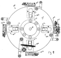
- Figure 9 is a top view swage dial assembly 101 having four multi-axis gripper stations.
- Figure 10(a) is cross-sectional view of the four station swage dial assembly 101 showing multi-axis gripper 155 in a retracted position.
- Figure 10(b) is cross-sectional view of the four station swage dial assembly 101 showing multi-axis gripper 155 in an extended position.
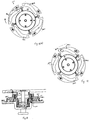
- Figure 11(a) is front face view of the multi-axis gripper 155 showing a surgical needle 21 in a relaxed engagement thereby, and additionally showing pin 147 in a retracted position.
- Figure 11(b) is front face view of the multi-axis gripper 155 showing a surgical needle 21 in an engaged position therein.
- Figure 11(c) is a hidden view of the actuating mechanism used to release the grip of the needle on the multi-axis gripper.
- Figure 12(a) is cut away top view of the cam dial plate 110 showing cam follower 165a in a retracted position within cam track 182a.
- Figure 12(b) is cut away top view of the cam dial plate 110 showing cam follower 165a in an extended position within cam track 182a.
- Figure 13 is a cross-sectional view of the cam dial 125 mounted coaxial with the swage dial 110 for cooperative rotational movement thereof, and showing cam followers 165a,c in their retracted positions within respective cam tracks 182a,c.
- Figure 14(a) is a top view of the swage assembly 400 of the instant invention.
- Figure 14(b) is a detailed view of the swage stop mechanism for swage assembly 400.
- Figure 15(a) is a detailed top view of the swage dies 420,430 of the swage assembly showing the recesses 434,435 formed in the swage die opening 432 located therebetween.
- Figure 15(b) is an enlarged view of the swage die opening shown encircled in Figure 15(a).
- Figure 1 is a block diagram generally illustrating the system 10 used to automatically draw an indefinite length of suture material for cutting a predetermined length thereof, and to automatically insert the cut suture within a suture receiving end of a surgical needle for automatic swaging thereof.
- the entire process takes place at a swaging station which comprises an apparatus used to draw and cut an indefinite length strand of suture material to a uniform length and insert the tip thereof within the suture receiving end of a surgical needle prior to swaging as described in copending patent application (attorney docket No. 8924) assigned to the same assignee of the present invention and incorporated by reference herein.
- surgical needles are individually loaded from a precision conveyor or any suitable means, onto a multi-axis gripper located on a rotary swage dial as indicated as step 12 and described in detail in copending patent application (attorney docket No. 8922) assigned to the same assignee of the present invention.
- the rotary swage dial is indexed so that the multi-axis gripper positions the needle in a precisely oriented position between two swaging dies of a swage assembly which is indicated as step 13 in Figure 1.
- an indefinite length of suture strand is drawn from a king spool along a single axis of a drawing tower and a tip thereof is stiffened and registered for insertion within the suture receiving end of the needle, as shown as step 11 in Figure 1.
- the multi-axis gripper releases its grip on the needle placed between the opening formed by the swaging dies.
- the gripper assembly at the drawing tower inserts the tip of the suture strand within the lower invertedly tapered alignment guide to position the tip within the suture receiving end of the needle, as shown as step 16.
- the swage cylinder is activated to automatically swage the suture strand to the needle while a cutting assembly simultaneously cuts the indefinite length of suture strand to a predetermined length.
- the multi-axis gripper is then retracted on the swage dial as shown as step 18.
- the armed needle is indexed to a pull-test station at step 19 where minimum pull testing and/or destructive pull testing may be performed.
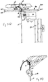
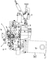
- a payoff assembly for accomplishing the task of automatically drawing an indefinite length suture material is embodied as a drawing tower 20 shown in Figure 2.
- the drawing tower 20 comprises left side rail and right side rail 24 mounted on suitable mounting block 25 and defining a drawing bed for drawing an indefinite length of suture material along a drawing axis therebetween.
- Located parallel to the left and right side rails 22,24 and suitably connected thereto are respective left guide rod 26 and right guide rod 28.
- the first gripper means or right gripper 32 reciprocates up and down along right guide rod 28 while the second gripper means or left gripper 30 reciprocates up and down the left guide rod 26.
- Each of the grippers 30,32 grip the suture material that is fed from a spool through pulley 35 located at the bottom of the drawing tower 20, and carries the material to the upper end of the tower.
- the right gripper 32 is mounted on right gripper carrier 33 for vertical movement along right guide rod 28, and the left gripper 30 is mounted on left gripper carrier 31 for vertical movement along left guide rod 26 as shown in Figure 2.
- Figure 4 illustrates a gripper 32 (and 30) having a gripper arm drive 61 that is pneumatically operated to drive pair of retractable gripper arms 65a, 65b toward each other to a suture gripping position, or, away from each other to an open position.
- Each retractable gripper arm is provided with a resilient, non-metallic pad 66a, 66b for gripping the suture material 55 at a free end thereof when actuated to the gripping position.
- gripper arms 65a,65b are retracted approximately 180 degrees apart in the direction indicated by the arrows of Figure 4 to the open position.
- the gripper arms 65a', 65b' do not interfere with the motion of the other vertically moving gripper as it reciprocates along the respective left or right rod, nor will it interfere with the cutter assembly 200 that cuts the strand to a predetermined length as will be explained below.
- the retractable nature of the grippers and of the cutting assembly enables single drawing axis operation.
- each gripper carrier and gripper thereof is designed to advance vertically along the respective left and right rods.
- the right gripper 32 and gripper carrier 33 is driven by right servo motor 38 which is mounted to the right side rail 24 by right motor mounting bracket 39.
- the left gripper 30 and gripper carrier 31 is driven by left servo motor 36 which is mounted to the left side rail 22 by left motor mounting bracket 37.
- both left and right servo motors are interfaced with and controlled by a control system computer, indicated generally as numeral 80 in Figure 2, and as explained in further detail in copending patent application (attorney docket No. 8927) assigned to the same assignee of the present invention.
- right servo motor 38 drives timing belt 43 which consequently enables vertical positioning of right gripper carrier 33 along right rod 28, while the left servo motor 36 drives timing belt 41 which consequently enables vertical positioning of left gripper carrier 31 along left rod 26.
- timing belt 43 is clamped to its respective gripper carrier 33 by a timing belt clamp 68 located on the back of the gripper carrier.
- a similar timing belt clamp (not shown) is provided on gripper carrier 31 for clamping timing belt 41 to enable vertical movement of gripper 30.
- Figure 2 shows timing belt 41 engaging upper left pulley 45 and lower left pulley 46 as well as idler pulleys 47,48 which are part of tensioner block 44 that adjusts the tension of the timing belt 41 and consequently of left gripper carrier 31.
- Figure 2 shows timing belt 43 engaging upper right pulley 51 and lower left pulley 52 as well as idler pulleys 53,54 which are part of tensioner block 45 that adjusts the tension of the timing belt 43 and consequently of right gripper carrier 33.
- Figure 2 additionally illustrates the tip and cut carrier 100 positioned along shafts 104 and 105 which are located parallel to respective left and right rods 26,28.
- Tip and cut carrier 100 provides the support for tipping assembly 300 that applies heat to a specific location of the suture material, and also provides support for the cutter assembly 200 that cuts the suture material.
- vertical movement of the tip and cut carrier 100 is accomplished by cranking handwheel 108 shown in Figure 2(b).
- Other embodiments may implement a computer controlled servo motor to vertically register the tip and cut carrier 100 prior to cutting the material.
- cranking handwheel 108 actuates a gearbox 113 that rotates chain drive sprocket 114.
- the gearbox 113 is mounted on a gearbox mounting bracket 122 which, in turn, is mounted to frame member 99.
- a cable chain 115 is engaged with chain drive sprocket 114 to actuate movement of the tip and cut carrier 100 as shown in Figure 2(b).
- the cable chain 115 also engages chain idler sprockets 118 and 119 which are rotatably mounted to upper tensioner pulley bracket 121 and lower tensioner pulley bracket 123, respectively.
- the vertical positioning of tensioner pulley brackets 121,123 may be adjusted to vary the slack in cable chain 115.
- Cable chain 115 also engages chain idler sprockets 127 and 129 which are suitably mounted on left side rail 22. As shown in Figure 3(a), the back 111 of tip and cut carrier 100 is clamped to cable chain 115.
- Both the stroke of the grippers 30,32 and the positioning of the tip and cut carrier 100 along drawing tower 20 dictates the length of the material that will be cut.
- proximity sensors 73,74, and 75 are positioned vertically at different heights along the drawing tower 20 to enable predetermination of the length of suture material to be cut.
- the locations of the proximity sensors 73,74, and 75 sense the positioning of the tip and cut carrier 100 as controlled by handcrank 108 in order to notify the control system 80 to change the reciprocating travel of grippers 30,32.
- proximity sensor 70 is mounted at a position along the right side rail 24 to verify that right gripper 32 has reached a desired position at the upper end of the tower 20 and notify the control system 80 and servomotor 38 accordingly.
- a proximity sensor (not shown) is mounted at the desired height along the left side rail 22 to verify that left gripper 30 has reached its desired position at the upper end of the drawing tower 20.
- Figure 2(a) shows suture material 55 being drawn by first gripper means or right gripper 32 from a king spool 50.
- the spool may be motor driven in which case a dancer assembly 59 may be provided to control the tension of the material as it is being fed.
- the lead gripper grips the suture material 55 in the above-described manner just slightly below its tipped end 58.
- the suture material 55 is first manually threaded through eyelet 56 and through optional knot detector 57 which senses any sudden change in the thickness of the suture material. Detection of a knot in suture material 55 will trigger the control system 80 to discard the cut strand of material at a subsequent operation.
- the suture material may be threaded within a tensioning (or dancer) assembly 59 which comprises a plurality of vertically spaced apart cones 23 each of which may be positioned laterally to increase or decrease the tension of the suture strand 55 as shown generally in Fig. 3(a).
- the suture material 55 is then advanced over pulleys 35a and 35b and further around pulley 112 which is mounted on the lower portion of tip and cut carrier 100 that is illustrated near the center of the tower as shown in Figure 2. Note that the lower threading pulley 35b, guide pulley 112, left gripper 30 and right gripper 32 are vertically aligned so that the cutter assembly 200 will always cut horizontally across the strand of material as will be discussed in detail below.
- the right servo motor 38 is enabled to drive the lead (right) gripper vertically along right rod 28 to register the tip of the indefinite length suture strand 55 for positioning within the suture receiving opening 29 of a precisely oriented surgical needle shown engaged by the multi-axis gripper 155 at the swaging assembly 400 located at the top of the drawing tower 20 as shown in Figure 3(b).
- the lead gripper servomotor advances the lead gripper for a long stroke distance, which may range from 12 inches to 36 inches depending upon the length of said suture strand desired, but is 16.1 inches in the preferred embodiment.
- the long stroke moves gripper 32 from a home position above the tip and cut carrier 100 and below the cutter assembly 200, to the position slightly below swaging assembly 400 as shown in Figure 2(a).
- the other servomotor positions the alternate gripper, for e.g., left gripper 30, along left rod 26 at the home position preferably above the tip and cut carrier 100 and below the position of the cutter assembly 200 as shown in Figure 2(a).
- the top or right gripper is gripping the material 55 at all times during the long stroke, while the bottom or left gripper is in its open position and not gripping.
- the process of advancing suture material 55 by alternating grippers at each cycle eliminates the recycle or return time for retaining the gripper to the original position. This makes faster machine speeds and hence, higher production rates possible.
- the lead gripper 32 again advances the suture material 55 for a short stroke distance of about 1.9 inches, so that the tipped end 58 will advance precisely within the suture receiving opening 29 of needle 21 for a swaging operation to take place at the swaging assembly 400.
- a tipped portion 78 of the material 55 that has been heated by tipping assembly 300 advances to a position slightly above the location of the left gripper 30 and adjacent the cutter assembly 200.
- the left gripper 30 (lower gripper) is actuated to grip the material 55 in the tipped portion 78, i.e., the portion of the suture material heated by tipping assembly 300 as shown in Figure 2(a), and the cutter assembly 200 is actuated to cut the tipped portion 78 of the suture material 55 so that the left gripper 30 is now gripping an indefinite length suture strand 55 having a tipped end 58.
- the top or right gripper 32 is actuated to release its grip on the definite length suture material.
- the lead gripper is temporarily halted so that a portion of the suture material 55 may be heated (tipped). Heating of the suture under tension and the subsequent cooling thereof will stiffen the material and aid in the positioning and subsequent swaging of the tip of the material within the confines of the surgical needle.
- the tipping assembly 300 is essentially an oven comprising a heat exchanger unit 305 that heats the air in the heater cavity 306.
- a pulse of incoming air is provided to the heat exchanger input 307, the heated air is displaced and it provides a pulse of heated air to a vertical cylindrical cavity 310 as shown in Figure 2(a).
- the heated air is forced through horizontal orifice 315 for a predetermined duration so that the length of suture material 55 suspended in tension through vertical cavity 310 will be heated.
- the control system computer 80 controls the duration of the heat pulse so that the material is adequately heated and will have sufficient time to cool before the cutting operation.
- the tipping assembly 300 is located at a position that is located slightly below the bottom or left gripper.
- FIGs 5 - 7 illustrate in detail the cutter assembly 200 which is suitably mounted to the tip and cut carrier 100 as shown in Figure 2(a).
- the cutter assembly comprises overcenter linkage 214 having a link arm 217 pivotally connected at one end thereof.
- a pivotal locator arm 220 is fixedly connected to link arm 217 at a second end thereof and is illustrated in Figure 6 as substantially transverse thereto.
- the other end of locator arm 220 is pivotally connected to a stationary guide mechanism 226.
- all pivotal linkages described herein are simple pin linkages, the actuation of which creates the dwell moment for cutting the suture strand and obviates the need for complicated cam, slots, and sliding mechanisms.
- the stationary guide 226 is located in a plane perpendicular to the drawing axis of the suspended strand of material 55, and is located a distance from the strand approximately equivalent to the length of locator arm 220.
- overcenter linkage 214, locator arm 220, and cutting blade 230 all lie in planes perpendicular to the drawing axis of the strand of material 55.
- a retractable ball slide 228 is mounted on the stationary guide 226 and coupled to overcenter linkage 214 for moving the overcenter linkage 214 and blade 230 along the stationary guide 226 in the direction indicated by arrow "A" in Figure 5 from a cutting position to a retracted position shown in Figure 6.
- the locator arm 220 is pivoted away from the strand 55 and the blade 230 is retracted.
- pneumatic air cylinder 222 enables reciprocating movement of the ball slide 228 along stationary guide 226 as shown in Figure 5.
- Locator arm 220 is provided with a V-shaped support notch 223 which functions to engage and position the strand of material 55 to be cut as the arm is pivoted into the cutting position.
- the V-shaped notch also functions to support the strand on two sides of the strand 55 while it is being horizontally cut on a third side.
- the cutting blade 230 of cutter assembly 200 is fixedly mounted to reciprocating ball slide 228 at a slight angle relative thereto and in a plane parallel with that of the locator arm 220.
- a single action by the pneumatic air cylinder 222 will enable movement of the reciprocating ball slide 228 along stationary guide 226. This consequently enables pivoting of locator arm 220 from its retracted position ( Figure 6), so that V-shaped notch 223 supports the strand 55 at two sides thereof while a third side of the strand bears upon the cutting edge of blade 230 as the blade moves towards the supported strand 55 traversing the drawing axis thereof.
- the strand 55 is cut in a dwell moment of the locator arm after the locator arm 220 has pivoted in the direction toward the blade 230 to the cutting position shown in Figure 7.
- the blade 230 slices the strand of material while it is held stationary by locator arm 220 by virtue of the angled orientation of the blade with respect to the axis of reciprocation illustrated in Figures 6 and 7.
- the slice ratio is 1:1, with the blade 230 angled at approximately 45 degrees relative to the axis of reciprocation, so that the strand 55 is cut an amount equivalent to the distance the blade 230 traverses the drawing axis.
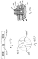
- the needle and suture swaging station includes a rotatable swage dial assembly 101 having four separate multi-axis gripper stations 82a,b,c,d where simultaneous operations are performed.
- the swage dial assembly 101 includes a swage dial 110 that is mounted to a rotatable central hub 99 which rotates under the control of a control system computer 80.
- a reciprocating carriage is provided at each station of the swage dial assembly 101.
- swage dial station 82a includes reciprocating carriage 150a
- station 82b includes reciprocating carriage 150b
- station 82c includes reciprocating carriage 150c
- station 82d includes reciprocating carriage 150d.
- each reciprocating carriage 150a,b,c,d for retractable movement therewith is a multi-axis gripper 155, one of which is shown connected to reciprocating carriage 150c in Figure 9.
- the multi-axis gripper 155 includes pins 142,146, and 148 as shown in Figure 11(a) that retain the surgical needle 21 in a fixed position.
- the needle 21 is being indexed to a different station as the swage dial rotates;
- the gripper 155 is in the extended position as shown in Figure 10(b)
- the needle is in one of the active stations, such as the station where it is registered for automatic swaging.
- a description of the preferred embodiment of the multi-axis gripper 155 follows hereinbelow.
- pins 142, 146, and 148 of the multi-axis gripper 155 extend perpendicularly from the gripper pin assembly 152 of the gripper to engage the arcuate portion 27 of needle 21, and to retain the needle in an oriented position.
- Figure 11(b) illustrates pin 142 located along the outer arcuate portion of the needle 21, while pin 146 supports the pin at the inner arcuate portion 27 of the needle 21.
- the barrel portion of the needle 21 fits adjacent protruding stop 148 located on the gripper pin assembly 152 of the gripper 155 as shown in Figure 11(b). The location of the stop 148 may be adjusted to accommodate the engagement of different size surgical needles.
- the gripper pin assembly 152 is replaceable with other gripper pin assemblies having the stop 148 positioned to accommodate different sized surgical needles.
- another pin such as pin 144 shown in Figures 11(a) and 11(b) may be provided for further support of the needle when in a relaxed position upon the multi-axis gripper.
- FIG. 11(b) The three pin engagement configuration shown in Figure 11(b) ensures that the needle 21 will not be displaced when the swage plate 110 is rotating, or, when the multi-axis gripper 155 is being retracted or extended.
- pin 142 is spring loaded and is retractable within guide 147 to release its grip of needle 21 prior to swaging thereof.
- Figure 11(c) illustrates plunger 149 connected to actuating lever 143 having a pin 145 mounted thereon and adjacent one leg of torsion spring 141.
- each cam follower 165a(b,c,d) is mounted to a cam slide 164 at one end of the reciprocating carriage 150a(b,c,d), and the multi-axis gripper 155 is connected to the cam slide 164 at the other end.
- Cam slide 164 is slidable within stationary guides 166,167 and is adapted for reciprocal movement when the cam follower 165 is actuated.
- cam follower 165 is a roller that fits within cam tracks of a rotatable cam dial assembly 120.
- Cam dial assembly 120 is shown in Figure 12(a) as comprising a cam dial plate 125 having four cam tracks 182a,b,c, and 182d which correspond to a swage dial stations 82a,b,c, and 82d, respectively.
- Each cam follower 165 is positioned within each respective cam track at each station for movement therein.
- cam follower 165a is positioned within cam track 182a
- cam follower 165c is positioned within cam track 182c.
- cam dial 125 is positioned above swage dial 110 and mounted coaxial therewith.
- the cam dial 125 is rotatable about a central shaft 199 and controlled by a separate rotary indexing transmission (not shown) so that it may rotate separately from the swage dial plate 110.
- Figure 12(a) shows cam follower 165a in a first retracted position within the cam track 182a. When in this position, reciprocating carriage and consequently multi-axis gripper 155 are in their retracted position as shown in Figure 10(a) discussed above.
- the cam dial plate 125 is rotated in the clockwise direction indicated by the arrow in Figure 12(a) for approximately 45 - 55 degrees relative to swage dial plate 110, forcing cam follower 165a in its cam track 182a to move toward the periphery of the dial as shown in Figure 12(b). Consequently, the cam slide 164, reciprocating carriage 150a, and the multi-axis gripper 155 move to the extended position as shown in Figure 10(b) and discussed above.
- cam dial 125 is rotated in the counter clockwise direction relative to the swage dial plate 110 for approximately 45 - 55 degrees, forcing cam follower 165a in its respective cam track 182a to move to its retracted position ( Figure 10(a)).
- each multi-axis gripper 155 is either extended or retracted by its respective cam track.
- the system is designed so that all processes performed at each station occur simultaneously and for approximately the same duration of time when the multi-axis grippers are in their extended position, for e.g., for needle pick-up, for needle swaging, or, for needle pull-testing.
- the timing of the system is operated under a control system, the description of which can be found in the above-mentioned copending patent application (attorney docket No. 8927).
- both swage dial plate 110 and cam dial plate 125 are rotated together for approximately 90 degrees to position the multi-axis gripper at the next station.
- cam dial plate 125 and the swage dial plate 110 are simultaneously rotated 90 degrees counterclockwise in Figure 13
- the gripper 155 that had received the needle at station 182a is now indexed to the position corresponding to station 182b for swaging a suture thereto.
- cam dial plate 125 is rotated an additional amount to cam the four multi-axis grippers to the extended position.
- the cam dial plate 125 and the swage dial plate 110 are simultaneously rotated counterclockwise so that the armed needle at station 182b is conveyed to the position corresponding to station 182c for pull-testing thereof.
- the operations performed concurrently at each station about the swage dial increases throughput to provide an output of pull-tested armed surgical needles at a rate of approximately 60 per minute in the preferred embodiment.
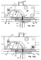
- Figures 3(b) - 3(g) illustrate the multi-axis needle gripper 155 and swaging and suture alignment dies shown in various stages of the suture insertion and needle swaging sequence. This sequence, and the interaction of the dies in relation to each other, the needle, and the insertion of the suture, accomplish the insert and swage function with minimal parts and simple motions.
- the multi-axis gripper 155 is radially extended from the swage dial in the manner described above to position the suture receiving end 29 of needle 21 between the funnel shaped die opening formed at the ends of two swage dies 420,430 as shown in Figure 3(b) and the partial perspective view of Figure 3(c).
- swage die 420 is fixed in position and swage die 430 is moved laterally toward the fixed swage die 420, as indicated by the arrow, to accomplish swaging of the suture receiving end of a needle placed therebetween.
- a funnel shaped die opening 432 having an exit diameter slightly larger than the diameter of the suture receiving end 29 of the needle is formed when the two swage dies 420,430 are positioned adjacent each other as shown in Figures 3(e) through 3(g).
- the ends of each of the swage dies 420,430 are provided with recesses 434,435, respectively, so that the metal deformation that occurs as a result of the swaging of the needle 21, does not result in metal flash or spurs at the suture receiving end 29 of the needle.
- different sets of swage dies may be provided, depending upon the size (diameters) of the needles and sutures to be swaged.
- the movable swage die 430 is temporarily moved apart.
- swage die 430 is moved apart from the fixed swage die 420 by actuating air cylinder 445 which provides a force upon cylinder rod 443 to enable swage die operating lever 447 to pivot about screw 449 and pull moveable swage die 430 a predetermined distance away from the fixed swage die 420.
- lever 447 is biased by spring 431 so that the movable swage die 430 will return toward the fixed swage die by the spring restoring force when the pressure provided by the air cylinder 445 is terminated.
- Figure 3(d) shows die 420 in its fixed position, and moveable die 430 in its spaced apart position prior to receiving the surgical needle 21 presented by multi-axis gripper 155.
- Suture alignment die 425 containing suture guide funnel half 425b, is positioned under die 420, and free to slide laterally within limits.
- Alignment die 425 has a tang 425a that protrudes into cavity 420a formed within swage die 420.
- Compression spring 420c bears against the back wall of cavity 420a and tang 425a such that funnel die 425 slides forward until it is constrained by cavity wall 420b.
- Suture alignment die 426 containing funnel half 427, is fastened to swage die 430 by suitable fastening means, described in detail below, and travels with it to the open position shown.
- the multi-axis gripper 155 is extended to position the suture receiving end of needle 21 within the opening 432 as shown in Figure 3(d) and Figure 14(a).
- the swage die 430, and suture alignment die 426 are moved toward needle 21 with the resilient spring force present in spring 431 ( Figure 14(a)) that is sufficient to enable the die 430 to grip and locate the suture receiving end 29 precisely against fixed swage die 420 without deforming the cavity of the suture receiving opening 29 formed therein.
- needle retaining pin 142 in multi-axis gripper 155 is raised by downward external force on plunger 149, as described above, thereby releasing the needle so that its position is determined by the grip of swaging dies 420 and 430.
- the motion of dies 426 and 430 cause the face 426a of suture alignment die 426 to come in contact with the corresponding face 425c of suture alignment die 425.
- the resilient force causing this motion is forceful enough to compress spring 420c, and move funnel die 425 to the left, such that tang 425a is no longer in contact with cavity wall 425b.
- Dimensioning of dies 430 and 426 is such that this motion results in the formation of two funnel halves 425b and 427 defining a smooth conical shape that is coaxial with the suture receiving end 29 of needle 21.
- Figure 3(e) shows the suture receiving end 29 being gripped by the swage dies 420,430 prior to suture insertion.
- the exit diameter of the conically shaped funnel guide formed of funnel halves 425b and 427 is preferably equal to or greater than the diameter of the suture tipped end 58 and smaller than the diameter of the suture receiving end 29 of the needle 21, as shown in Figure 3(f), so that the tipped end 58 of the suture strand may be easily inserted therein.
- Figure 3(f) shows suture gripper 65a moved vertically to the insertion position, which causes stiffened suture end 58 to enter funnel 425b and 427, and be guided into the suture receiving cavity 29 of needle 21 axially aligned therewith.
- a pneumatic air cylinder supplies air pressure to swage air cylinder 450 which actuates cylinder rod 433 that bears on lever 447 to thrust movable swage die 430 toward the fixed swage die to accomplish the swaging of the suture receiving end of the needle placed therebetween.
- Air pressure is supplied to the swage cylinder 450 via ports 451,452 under the control of the control system computer 80.
- Figure 3(g) shows the completed swage stroke.
- the swage die 430 has been driven to a fixed stop by the swage cylinder, which exerted sufficient force to deform the suture receiving end 29 of needle 21.
- suture alignment die 426 further displaces funnel die 425, causing additional compression of spring 420c.
- the moveable swage die 430 comes to an automatic stop by a swage stop mechanism herein described.
- movable swage die 430 and suture alignment die 426 are mechanically held coincident to each other by shouldered post 471, the smaller diameter of which is a light press fit into the mating hole in die 430.
- Cap screw 474 with washer 476 retain the post in die 430.
- the larger diameter of post 471, below die 430 extends through a light press fit hole in funnel die 426 so that the right hand swage and funnel dies are linked to move together laterally during the swaging cycle.
- the lower portion of shouldered post 471 extends through funnel die 426 into groove 479, which is cross milled into swage assembly frame 480.
- the swage cylinder drives this die assembly to the left until it is positively stopped by the lower portion of post 471 striking wall 481 of groove 479. This stalls air cylinder 450, so that the stroke of the moveable swage die assembly shown is always the same for repeating cycles of the machines.
- both swage dies 420,430 may be movable towards each other to accomplish swaging.
- an adjustable swage stop mechanism for changing the swage stroke distance of one of the movable dies may be provided to further control the swaging pressure applied to the suture receiving opening.
- a needle fence assembly 428 is provided to ensure that the needle 21 does not tip or become misaligned when the needle is being swaged.
- the needle fence assembly 428 comprises a needle fence plate 429 whose distance from the swage die opening 432 is adjustable depending upon the size of the surgical needle to be swaged.
- the degree of swage compression imparted on the needle, and resulting strength of grip by the needle on the suture is adjusted by precise positioning of the fixed die 420.
- servomotor 460 drives pulley 462 via timing belt 461 which rotates the swage adjust screw 475.
- the pitch of the swage adjust screw 475 is selected to move sliding wedge 465 a small distance.
- the swage die 420 has a complementary ramp angle 423 at the opposite end which bears on the wedge 465 to retract or advance the position of the swage die 420 a precise distance proportional to the movement of the sliding wedge.
- the rotation of the swage adjust screw 475 and motion of the sliding wedge 465 results in transverse movement of the swage die 420 to thereby finely adjust its fixed position.
- the position of the fixed swage die 420 may be moved further away from the suture drawing axis so that less swaging pressure is applied to the needle when the movable swage die 430 is thrust towards the fixed die to a stop.
- control system computer 80 will send the appropriate signals to automatically direct the servomotor 460 to adjust the position of the swage adjust screw 475, and hence, the position of the fixed die 420, in accordance with the pull-out test values of the needle-suture bond as measured downstream of the swaging station by an automatic pull-test system as explained in further detail in copending patent application (attorney docket No. 8923) assigned to the same assignee of the present invention.
- appropriate signals may be sent to automatically direct the servomotor 460 to adjust the rotational position of the swage adjust screw 475 in accordance with stored statistical results of the pull-testing occurring at the pull-test station.
- Automatic pull-testing of the armed needle is desirable to ensure that the upstream swaging dies are optimally positioned to avoid over-swaging the needle-suture bond and hence, preventing the likelihood of clip-off, and, to avoid under-swaging the needle-suture bond to prevent the chance of pull-out.
- the left gripper 30 secures the suture strand, and the suture material 55 is cut by the cutting assembly 200 in the manner described above and as indicated in step 17 in Figure 1.
- the cutter assembly 200 is positioned slightly above the left gripper 30 so that the indefinite length suture strand 55 will be gripped when the swaged strand is cut.
- the left gripper 30 is now gripping the suture material 55 with a tipped end 58 and it now becomes the lead gripper.
- a vacuum air flow is energized to pull the strand of material 55 toward the nylon screen 251 to more precisely locate the suture strand in the target zone of the cutter.
- the tail end 58 of the length of suture material that had been swaged to the surgical needle is sucked into a large vacuum pipe 275, that is connected to a vacuum assembly (not shown) by vacuum hose 280 as shown in Figure 2(a).
- the vacuum created in vacuum pipe 275 exerts a mild tension in the strand of material to keep the tail end from entanglement or coming into contact with the machinery. However, it is mild enough to allow the strand to be pulled out of the pipe 275 as the armed needle and suture are indexed for further downstream processes.
- the movable die 430 is again retracted by air cylinder 445 and the pin 142 of the multi-axis gripper 155 is actuated to engage the armed needle as described above. Subsequently, the multi-axis gripper 155 is retracted (step 18) to its position along the swage dial 101 for subsequent indexing to the next station, for e.g., pull-test station, or, for further processing (step 19).
- the cycle continues at the swaging station with the left gripper becoming the top gripper and vertically drawing the suture material 55 along the height of the drawing tower 20 to position the next strand to be cut for insertion within the surgical needle.
- the process of advancing suture material 55 by alternating grippers at each cycle eliminates the recycle or return time for retaining the gripper to the original position.
Applications Claiming Priority (2)
| Application Number | Priority Date | Filing Date | Title |
|---|---|---|---|
| US181599 | 1994-01-13 | ||
| US08/181,599 US5477609A (en) | 1994-01-13 | 1994-01-13 | Needle and suture swaging station |
Publications (2)
| Publication Number | Publication Date |
|---|---|
| EP0663189A1 true EP0663189A1 (fr) | 1995-07-19 |
| EP0663189B1 EP0663189B1 (fr) | 2001-06-13 |
Family
ID=22664969
Family Applications (1)
| Application Number | Title | Priority Date | Filing Date |
|---|---|---|---|
| EP95300205A Expired - Lifetime EP0663189B1 (fr) | 1994-01-13 | 1995-01-13 | Dispositif à rétreindre une aiguille chirurgicale et un fil de suture |
Country Status (6)
| Country | Link |
|---|---|
| US (2) | US5477609A (fr) |
| EP (1) | EP0663189B1 (fr) |
| JP (1) | JP3633983B2 (fr) |
| AU (1) | AU689162B2 (fr) |
| CA (1) | CA2139998A1 (fr) |
| DE (1) | DE69521222T2 (fr) |
Cited By (1)
| Publication number | Priority date | Publication date | Assignee | Title |
|---|---|---|---|---|
| EP0826337A1 (fr) * | 1996-02-16 | 1998-03-04 | Nippon Shoji Kaisha Ltd. | Dispositif servant a fixer un fil de couture a une aiguille |
Families Citing this family (27)
| Publication number | Priority date | Publication date | Assignee | Title |
|---|---|---|---|---|
| CA2139980A1 (fr) | 1994-01-13 | 1995-07-14 | David Demarest | Systeme de coupe des fils de suture |
| US5540778A (en) * | 1994-09-21 | 1996-07-30 | United States Surgical Corporation | Method and apparatus for tipping, cutting, and sorting sutures |
| US5664404A (en) * | 1995-08-31 | 1997-09-09 | Ethicon, Inc. | Automatic zipper package winding and packaging machine |
| US5661954A (en) * | 1995-08-31 | 1997-09-02 | Ethicon, Inc. | Needle feed wheel and needle transfer mechanism |
| US5660024A (en) * | 1995-08-31 | 1997-08-26 | Ethicon, Inc. | Zipper package winding tool mechanism |
| JP3327765B2 (ja) * | 1996-02-16 | 2002-09-24 | 株式会社アズウェル | 針付縫合糸の製造装置 |
| US5975876A (en) * | 1996-05-10 | 1999-11-02 | Ethicon, Inc. | Combined apparatus for heating and cutting a surgical suture tip |
| US5726422A (en) * | 1996-05-10 | 1998-03-10 | Ethicon, Inc. | Apparatus with moving clamp for making surgical sutures, and method for using same |
| US5937504A (en) * | 1997-04-30 | 1999-08-17 | Ethicon, Inc. | Stand alone swage dial assembly |
| US6032343A (en) * | 1997-02-24 | 2000-03-07 | Ethicon, Inc. | Automated swage wind and packaging machine |
| US6012216A (en) * | 1997-04-30 | 2000-01-11 | Ethicon, Inc. | Stand alone swage apparatus |
| US5844142A (en) * | 1997-04-30 | 1998-12-01 | Ethicon, Inc. | Pull test apparatus for permanently attached sutures |
| US5873212A (en) * | 1997-04-30 | 1999-02-23 | Ethicon, Inc. | Stand alone swage dial drive assembly |
| US6014851A (en) * | 1998-02-06 | 2000-01-18 | Ethicon, Inc. | Package feed arrangement in a machine for the automated packaging of needles and attached sutures |
| US5964075A (en) * | 1998-02-06 | 1999-10-12 | Ethicon, Inc. | Cover or label-applying arrangement in a machine for the automated packaging of needles and attached sutures |
| US5987848A (en) * | 1998-02-06 | 1999-11-23 | Ethicon, Inc. | Needle transfer arrangement in a machine for the automated packaging of needles and attached sutures |
| US5956927A (en) * | 1998-02-06 | 1999-09-28 | Ethicon, Inc. | Suture capture and tensioning arrangement in a machine for the automated packaging of needles and attached sutures |
| US5983601A (en) * | 1998-02-06 | 1999-11-16 | Ethicon, Inc. | Machine for the automated packaging of needles and attached sutures |
| US6001121A (en) * | 1998-04-14 | 1999-12-14 | Ethicon, Inc. | Surgical suture having a thermally formed tip, and apparatus and method for making same |
| US6024757A (en) * | 1998-04-14 | 2000-02-15 | Ethicon, Inc. | Method for cutting a surgical suture tip |
| US6035751A (en) * | 1998-04-28 | 2000-03-14 | Ethicon, Inc. | Method for cutting a surgical suture at two locations |
| US6877352B1 (en) * | 2003-07-10 | 2005-04-12 | System for securing a suture to a needle in a swaged fashion | |
| US7185411B2 (en) * | 2004-01-30 | 2007-03-06 | Ethicon, Inc. | Method and apparatus for forming fine gauge and monofilament single and double-armed sutures |
| US8389892B2 (en) * | 2009-05-20 | 2013-03-05 | Ethicon, Inc. | X-ray microscopy for characterizing hole shape and dimensions in surgical needles |
| CN103203610B (zh) * | 2013-03-19 | 2015-04-22 | 江苏食品职业技术学院 | 缝合线自动装配机 |
| CN107049390B (zh) * | 2016-11-25 | 2019-02-05 | 温州科技职业学院 | 一种外科缝纫针穿线装置 |
| CN108371549B (zh) * | 2018-04-17 | 2019-09-06 | 杨东 | 一种用于植皮区域和手术切口创面区域的缝合器械 |
Citations (5)
| Publication number | Priority date | Publication date | Assignee | Title |
|---|---|---|---|---|
| JPS63212027A (ja) * | 1987-02-26 | 1988-09-05 | Matsutani Seisakusho:Kk | 糸付縫合針の製造方法 |
| JPS63299834A (ja) * | 1987-05-30 | 1988-12-07 | Matsutani Seisakusho:Kk | 湾曲縫合針の自動処理装置 |
| FR2632850A1 (fr) * | 1988-06-18 | 1989-12-22 | Keisei Medical Ind | Appareil pour fixer un fil a une aiguille chirurgicale |
| JPH0382458A (ja) * | 1989-08-28 | 1991-04-08 | Matsutani Seisakusho Co Ltd | 糸付縫合針及び前記糸付縫合針の加工方法 |
| EP0428253A1 (fr) * | 1989-11-14 | 1991-05-22 | United States Surgical Corporation | Procédé et dispositif pour effectuer un traitement thermique d'extrémités de fils de suture |
Family Cites Families (9)
| Publication number | Priority date | Publication date | Assignee | Title |
|---|---|---|---|---|
| US3611551A (en) * | 1969-08-25 | 1971-10-12 | Deknatel Inc | Method for attaching suture and needle |
| US3980177A (en) * | 1973-10-26 | 1976-09-14 | Johnson & Johnson | Controlled release suture |
| US4054144A (en) * | 1976-05-28 | 1977-10-18 | American Cyanamid Company | Short-crimp surgical needle |
| US4672871A (en) * | 1985-06-27 | 1987-06-16 | Artos Engineering Company | Adjustable apparatus for cutting and conveying wire segments of various lengths |
| US4722384A (en) * | 1986-09-29 | 1988-02-02 | Matsutani Seisakusho Co., Ltd. | Method of and apparatus for attaching suture to operating needle |
| US5226336A (en) * | 1987-07-30 | 1993-07-13 | American Cyanamid Company | Apparatus for manufacturing a surgical suture |
| US4832025A (en) * | 1987-07-30 | 1989-05-23 | American Cyanamid Company | Thermoplastic surgical suture with a melt fused length |
| US4806737A (en) * | 1987-07-30 | 1989-02-21 | American Cyanamid Company | Apparatus for manufacturing a surgical suture |
| JPH01317430A (ja) * | 1988-06-18 | 1989-12-22 | Keisei Ika Kogyo Kk | 手術用縫合針の組立装置 |
-
1994
- 1994-01-13 US US08/181,599 patent/US5477609A/en not_active Expired - Lifetime
-
1995
- 1995-01-11 AU AU10148/95A patent/AU689162B2/en not_active Expired - Fee Related
- 1995-01-11 CA CA002139998A patent/CA2139998A1/fr not_active Abandoned
- 1995-01-13 EP EP95300205A patent/EP0663189B1/fr not_active Expired - Lifetime
- 1995-01-13 JP JP02109995A patent/JP3633983B2/ja not_active Expired - Lifetime
- 1995-01-13 DE DE69521222T patent/DE69521222T2/de not_active Expired - Lifetime
- 1995-03-09 US US08/401,365 patent/US5485668A/en not_active Expired - Lifetime
Patent Citations (5)
| Publication number | Priority date | Publication date | Assignee | Title |
|---|---|---|---|---|
| JPS63212027A (ja) * | 1987-02-26 | 1988-09-05 | Matsutani Seisakusho:Kk | 糸付縫合針の製造方法 |
| JPS63299834A (ja) * | 1987-05-30 | 1988-12-07 | Matsutani Seisakusho:Kk | 湾曲縫合針の自動処理装置 |
| FR2632850A1 (fr) * | 1988-06-18 | 1989-12-22 | Keisei Medical Ind | Appareil pour fixer un fil a une aiguille chirurgicale |
| JPH0382458A (ja) * | 1989-08-28 | 1991-04-08 | Matsutani Seisakusho Co Ltd | 糸付縫合針及び前記糸付縫合針の加工方法 |
| EP0428253A1 (fr) * | 1989-11-14 | 1991-05-22 | United States Surgical Corporation | Procédé et dispositif pour effectuer un traitement thermique d'extrémités de fils de suture |
Non-Patent Citations (3)
| Title |
|---|
| PATENT ABSTRACTS OF JAPAN vol. 12, no. 490 (M - 779) 21 December 1988 (1988-12-21) * |
| PATENT ABSTRACTS OF JAPAN vol. 13, no. 130 (M - 808) 30 March 1989 (1989-03-30) * |
| PATENT ABSTRACTS OF JAPAN vol. 15, no. 252 (C - 844) 26 June 1991 (1991-06-26) * |
Cited By (3)
| Publication number | Priority date | Publication date | Assignee | Title |
|---|---|---|---|---|
| EP0826337A1 (fr) * | 1996-02-16 | 1998-03-04 | Nippon Shoji Kaisha Ltd. | Dispositif servant a fixer un fil de couture a une aiguille |
| EP0826337A4 (fr) * | 1996-02-16 | 1999-12-01 | Nippon Shoji Kaisha Ltd | Dispositif servant a fixer un fil de couture a une aiguille |
| KR100465461B1 (ko) * | 1996-02-16 | 2005-07-18 | 알프레사 파마 가부시키가이샤 | 바늘부착봉합실의제조장치 |
Also Published As
| Publication number | Publication date |
|---|---|
| JP3633983B2 (ja) | 2005-03-30 |
| CA2139998A1 (fr) | 1995-07-14 |
| AU1014895A (en) | 1995-07-20 |
| US5477609A (en) | 1995-12-26 |
| JPH0866401A (ja) | 1996-03-12 |
| US5485668A (en) | 1996-01-23 |
| DE69521222T2 (de) | 2001-11-08 |
| EP0663189B1 (fr) | 2001-06-13 |
| DE69521222D1 (de) | 2001-07-19 |
| AU689162B2 (en) | 1998-03-26 |
Similar Documents
| Publication | Publication Date | Title |
|---|---|---|
| EP0663189B1 (fr) | Dispositif à rétreindre une aiguille chirurgicale et un fil de suture | |
| US6128816A (en) | Suture cutting method | |
| EP0663185B1 (fr) | Dispositif de coupe, pour couper des longueurs de fils déterminées | |
| US5473810A (en) | Needle-suture assembly and packaging system | |
| US5438746A (en) | Needle threading and swaging system | |
| US5918284A (en) | Pull test apparatus for permanently attached sutures | |
| JP4153140B2 (ja) | ダブルアーム付き縫合糸を形成するための方法及び装置 | |
| US4503664A (en) | Rope chain machine | |
| JPH1158146A (ja) | チューブを長尺物へ挿入する方法とその挿入機 | |
| US5937504A (en) | Stand alone swage dial assembly | |
| US4439919A (en) | Automatic lead making apparatus | |
| US5873212A (en) | Stand alone swage dial drive assembly | |
| EP0801826A1 (fr) | Appareil de fabrication de harnais de cables | |
| US20010032359A1 (en) | Method and machine for the manufacture of metallic frames for inner spring mattresses | |
| JPH06290846A (ja) | 電線の端子圧着装置 | |
| JPH06290848A (ja) | 端子供給機構 | |
| JPH06290845A (ja) | 電線の切断および端子圧着装置 | |
| JPH06290847A (ja) | 電線の送り出し機構 |
Legal Events
| Date | Code | Title | Description |
|---|---|---|---|
| PUAI | Public reference made under article 153(3) epc to a published international application that has entered the european phase |
Free format text: ORIGINAL CODE: 0009012 |
|
| AK | Designated contracting states |
Kind code of ref document: A1 Designated state(s): DE FR GB |
|
| 17P | Request for examination filed |
Effective date: 19951220 |
|
| 17Q | First examination report despatched |
Effective date: 19990202 |
|
| GRAG | Despatch of communication of intention to grant |
Free format text: ORIGINAL CODE: EPIDOS AGRA |
|
| GRAG | Despatch of communication of intention to grant |
Free format text: ORIGINAL CODE: EPIDOS AGRA |
|
| GRAH | Despatch of communication of intention to grant a patent |
Free format text: ORIGINAL CODE: EPIDOS IGRA |
|
| GRAH | Despatch of communication of intention to grant a patent |
Free format text: ORIGINAL CODE: EPIDOS IGRA |
|
| GRAA | (expected) grant |
Free format text: ORIGINAL CODE: 0009210 |
|
| AK | Designated contracting states |
Kind code of ref document: B1 Designated state(s): DE FR GB |
|
| REF | Corresponds to: |
Ref document number: 69521222 Country of ref document: DE Date of ref document: 20010719 |
|
| ET | Fr: translation filed | ||
| REG | Reference to a national code |
Ref country code: GB Ref legal event code: IF02 |
|
| PLBE | No opposition filed within time limit |
Free format text: ORIGINAL CODE: 0009261 |
|
| STAA | Information on the status of an ep patent application or granted ep patent |
Free format text: STATUS: NO OPPOSITION FILED WITHIN TIME LIMIT |
|
| 26N | No opposition filed | ||
| PGFP | Annual fee paid to national office [announced via postgrant information from national office to epo] |
Ref country code: DE Payment date: 20140108 Year of fee payment: 20 |
|
| PGFP | Annual fee paid to national office [announced via postgrant information from national office to epo] |
Ref country code: FR Payment date: 20140108 Year of fee payment: 20 |
|
| PGFP | Annual fee paid to national office [announced via postgrant information from national office to epo] |
Ref country code: GB Payment date: 20140108 Year of fee payment: 20 |
|
| REG | Reference to a national code |
Ref country code: DE Ref legal event code: R071 Ref document number: 69521222 Country of ref document: DE |
|
| REG | Reference to a national code |
Ref country code: GB Ref legal event code: PE20 Expiry date: 20150112 |
|
| PG25 | Lapsed in a contracting state [announced via postgrant information from national office to epo] |
Ref country code: GB Free format text: LAPSE BECAUSE OF EXPIRATION OF PROTECTION Effective date: 20150112 |