EP0662736B1 - Drehender elektrischer Schleifring mit Mehrdrahtbürsten - Google Patents
Drehender elektrischer Schleifring mit Mehrdrahtbürsten Download PDFInfo
- Publication number
- EP0662736B1 EP0662736B1 EP94400681A EP94400681A EP0662736B1 EP 0662736 B1 EP0662736 B1 EP 0662736B1 EP 94400681 A EP94400681 A EP 94400681A EP 94400681 A EP94400681 A EP 94400681A EP 0662736 B1 EP0662736 B1 EP 0662736B1
- Authority
- EP
- European Patent Office
- Prior art keywords
- rotating electrical
- strands
- brushes
- commutator according
- electrical commutator
- Prior art date
- Legal status (The legal status is an assumption and is not a legal conclusion. Google has not performed a legal analysis and makes no representation as to the accuracy of the status listed.)
- Expired - Lifetime
Links
- 239000004020 conductor Substances 0.000 claims description 7
- 244000007853 Sarothamnus scoparius Species 0.000 description 13
- 230000000694 effects Effects 0.000 description 3
- 239000012777 electrically insulating material Substances 0.000 description 3
- 239000000463 material Substances 0.000 description 3
- 238000003466 welding Methods 0.000 description 3
- 230000005540 biological transmission Effects 0.000 description 2
- 238000006073 displacement reaction Methods 0.000 description 2
- 238000004519 manufacturing process Methods 0.000 description 2
- 229910001369 Brass Inorganic materials 0.000 description 1
- 230000001133 acceleration Effects 0.000 description 1
- 229910045601 alloy Inorganic materials 0.000 description 1
- 239000000956 alloy Substances 0.000 description 1
- 238000005452 bending Methods 0.000 description 1
- 239000010951 brass Substances 0.000 description 1
- 230000002089 crippling effect Effects 0.000 description 1
- 238000005520 cutting process Methods 0.000 description 1
- 238000013016 damping Methods 0.000 description 1
- 238000009826 distribution Methods 0.000 description 1
- PCHJSUWPFVWCPO-UHFFFAOYSA-N gold Chemical compound [Au] PCHJSUWPFVWCPO-UHFFFAOYSA-N 0.000 description 1
- 239000010931 gold Substances 0.000 description 1
- 229910052737 gold Inorganic materials 0.000 description 1
- 238000010438 heat treatment Methods 0.000 description 1
- 229910001092 metal group alloy Inorganic materials 0.000 description 1
- 238000013021 overheating Methods 0.000 description 1
- 238000003825 pressing Methods 0.000 description 1
- 230000009467 reduction Effects 0.000 description 1
- 239000007787 solid Substances 0.000 description 1
Images

Classifications
-
- H—ELECTRICITY
- H01—ELECTRIC ELEMENTS
- H01R—ELECTRICALLY-CONDUCTIVE CONNECTIONS; STRUCTURAL ASSOCIATIONS OF A PLURALITY OF MUTUALLY-INSULATED ELECTRICAL CONNECTING ELEMENTS; COUPLING DEVICES; CURRENT COLLECTORS
- H01R39/00—Rotary current collectors, distributors or interrupters
- H01R39/64—Devices for uninterrupted current collection
-
- H—ELECTRICITY
- H01—ELECTRIC ELEMENTS
- H01R—ELECTRICALLY-CONDUCTIVE CONNECTIONS; STRUCTURAL ASSOCIATIONS OF A PLURALITY OF MUTUALLY-INSULATED ELECTRICAL CONNECTING ELEMENTS; COUPLING DEVICES; CURRENT COLLECTORS
- H01R39/00—Rotary current collectors, distributors or interrupters
- H01R39/02—Details for dynamo electric machines
- H01R39/18—Contacts for co-operation with commutator or slip-ring, e.g. contact brush
- H01R39/24—Laminated contacts; Wire contacts, e.g. metallic brush, carbon fibres
Definitions
- the invention relates to an electrical collector turning comprising one or more slip rings and at least one multi-strand broom in lateral support sliding against each slip ring, so that allow the transmission of one or more signals electric between two rooms able to be animated by a relative rotational movement.
- the rotating electrical collectors are devices that transmit one or more several electrical signals between a fixed part or stator, and a moving part or rotor. Such devices are used in many industrial sectors among which we will cite, only as examples, machine tools, transport air, naval and terrestrial, radars, etc.
- the rotor of a rotating electrical collector includes a number of rings electrically conductive equal to the number of electrical signals that must pass the device. These rings electrically conductive are arranged on an axis electrically insulating and separated from each other by a electrically insulating material.
- the stator of rotating electrical collectors generally includes, opposite each of electrically conductive rings, at least two brushes most often made up of a strand single electrically conductive continuously rubbing on the corresponding ring.
- Gorges can be machined on electrically conductive rings for guide the brushes.
- the electrical collectors single-strand brushes therefore have the main disadvantages the introduction of electrical noise into the signals they transmit, sometimes a lifetime insufficient and a relative linear speed between slip rings and brushes which cannot exceed certain limits.
- the majority of the strands of the bundle forming a broom is not directly in contact with the slip ring. Therefore, the transmission electrical signals are made from strand to strand up to the slip ring, which is not satisfactory from the point of view of resistance variation of contact.
- Document EP-A-54 380 describes a rotary electrical collector provided with a multi-strand brush also formed of a large number of metallic wires of very small diameter, applied tangentially in a rectangular groove, in U or V shape of a ring collector.
- the subject of the invention is precisely a rotating electrical collector with brushes an original design allowing to reduce noticeably the electrical noises due to vibrations, compared to single-wire brushes, while allowing longer service life and higher linear speeds to those allowed with single-wire brushes, without risk creation of short circuits due to breaks broom strands, and whatever the diameter slip rings, in particular for very small collectors used in gyroscopic applications.
- this result is obtained by means of an electrical collector rotating at multi-strand brooms, suitable for placing between two parts likely to be rotated relative, this collector comprising at least one ring manifold provided with an annular groove, made of an electrically material conductor and carried by a first of said parts and at least one multi-strand broom made of a material electrically conductive and carried by the second piece so as to be in lateral sliding contact against the slip ring, according to a determined bearing force, characterized by the fact that each multi-strand broom includes a bundle of two to five strands juxtaposed, received in the annular groove of the slip ring so that each of them is simultaneously in contact with this throat.
- multi-strand brushes a limited number of strands arranged so as to be all in contact with the annular groove of the ring collector significantly reduces variations dynamic electrical resistance to surfaces of contact, in particular by providing self-damping vibrations. This results in a significant decrease electrical noise generated in the collector as well as a marked improvement in service life and linear speeds likely to be reached, compared to single-wire brush collectors.
- limiting the number of strands constituting each broom at a very low number allows to give these strands a sufficient diameter to avoid any risk of rupture likely to produce unacceptable short circuits in the collector.
- each multi-strand broom further includes a base having a receptacle in which is received one end of the bundle and a support force adjustment rod, carrying the receptacle and able to be fixed on a terminal block of the second room.
- This rod is advantageously a rod straight folded to form an angle that determines the support force.
- the strands are welded in a blind hole in receptacle.
- each broom present either a section V-shaped, i.e. a U-shaped section.
- two the brushes are preferably in sliding lateral support, opposite direction, in each of the annular grooves.
- the rotating electric collector illustrated schematically in Figure 1 comprises a rotor 10 and a stator 12.
- the rotor 10 mainly comprises an axis 14, made of an electrically insulating material, on which are fitted with slip rings 16, made of an electrically conductive material. These slip rings 16 are separated from each other others by electrically insulating rings 18.
- the number of rings 16 and 18 can be any and basically depends on the number of signals to be transmitted through the collector.
- each of the slip rings 16 electrical conductors inside the axis 14, so as to connect each of the slip rings 16 to systems capable of receive or transmit electrical signals by the rings.
- the axis 14 of the rotor 10 is supported by two flanges 22 of stator 12, via two bearings 24.
- the stator 12 of the rotating electrical collector further comprises a tubular piece 26 which connects between them the two flanges 22 coaxially with the axis 14, around slip rings 16 and insulating rings 18.
- the tubular part 26 carries a terminal block 27 in one electrically insulating material, supporting blades conductive.
- This terminal block 27 supports, in a cutting plane radially each of the slip rings 16, two multi-strand brushes 28 which are arranged so as to be in sliding lateral support, in opposite direction, on the corresponding slip ring 16. More precisely, each pair of brushes 28 is supported in a groove of guide 30 of the corresponding slip ring 16, this groove 30 advantageously having a section V-shaped ( Figure 3) or U-shaped ( Figure 4). Fixation two brushes 28 of the same pair on the terminal block 27 is carried out in two neighboring locations, such so that the brushes 28 are arranged symmetrically with respect to a plane passing through the geometric axis of axis 14.
- each of the multi-strand brushes 28 comprises a bundle of n juxtaposed strands, n being able to vary between 2 and 5 and being advantageously equal to 3, as illustrated in the figures.
- the strands 32 are all identical and they are made of an electrically conductive material, mechanically resistant and having good elasticity. This material can in particular consist of a metallic alloy such as a gold-based alloy.
- each of the strands 32 of the broom 28 is advantageously between 0.15 mm and 0.25 mm. This dimension avoids any risk of breakage and therefore short circuit inside the collector, without significantly increasing the size of the brushes.
- Each of the multi-strand brushes 28 includes plus a base 34 by which the strands 32 are mounted on terminal block 27 of the stator.
- This base 34 is made of an electrically conductive material such than brass.
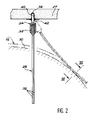
- a first end of the beam formed by the strands 32 is embedded in a blind hole formed in a tubular receptacle 36 constituting a part of the base 34.
- the base 34 further comprises a rod 38 which is aligned with the strands 32 when these the latter are embedded in receptacle 36.
- the three strands 32 of each of the brushes are embedded in the blind hole of receptacle 36 and they are welded to it by welding 40.
- This welding 40 can be carried out electrically.
- the strands 32 are then straight and aligned with the rod 38 as shown in solid line in Figure 2.
- the rod 38 is bent at a determined angle, in a plane perpendicular to the geometric axis of axis 14, as shown in dashed lines in the figure 2. This angle is such that when the rotor is in place, the strands 32 of the brush 28 are in lateral support sliding in the groove 30 of the corresponding ring 16, by undergoing a certain outward bending which determines the support force.
- groove 30 with V-shaped section has been replaced by a U-shaped section groove.
- characteristic notably improves the distribution between the strands 32 of the loads due to the force with which the brush is applied against the groove, while preserving the guiding effect provided by this throat.
Landscapes
- Motor Or Generator Current Collectors (AREA)
Claims (9)
- Drehender elektrischer Schleifring mit Mehrdrahtbürsten, geeignet zwischen zwei Teilen (10,12) angebracht zu werden, die eine Relativdrehbewegung ausführen, wobei dieser Schleifring wenigstens einen mit einer Ringnut (30) versehenen Kollektorring (16) umfaßt, hergestellt aus einem elektrisch leitenden Material und getragen durch ein erstes der genannten Teile, und wenigstens eine Mehrdrahtbürste (28), hergestellt aus einem elektrisch leitenden Material und derart durch das zweite Teil (12) getragen, daß sie, sich mit einer bestimmten Abstützkraft seitlich abstützend, auf dem Kollektorring gleitet,
dadurch gekennzeichnet,
daß jede Mehrdrahtbürste (28) ein Bündel von zwei bis fünf derart in einer Ringnut (30) des Kollektorrings (16) nebeneinanderliegende Bürstendrähte (32) aufweist, daß jeder von ihnen simultan Kontakt hat mit dieser Nut. - Drehender elektrischer Schleifring nach Anspruch 1, dadurch gekennzeichnet, daß jede Mehrdrahtbürste (28) drei nebeneinanderliegende Bürstendrähte (32) umfaßt.
- Drehender elektrischer Schleifring nach einem der Ansprüche 1 und 2, dadurch gekennzeichnet, daß jede Mehrdrahtbürste (28) zudem einen Sockel (34) umfaßt, gebildet durch eine Fassung (36) für das Ende des Bündels, und einen Stift (38) zur Einstellung der Abstützkraft, der die Fassung trägt und in einer Befestigungseinrichtung (27) des zweiten Teils (12) festgemacht werden kann.
- Drehender elektrischer Schleifring nach Anspruch 3, dadurch gekennzeichnet, daß der Stift (38) ein gerader Stift ist, der umgebogen wird, um einen Winkel zu bilden, der die Abstützkraft bestimmt.
- Drehender elektrischer Schleifring nach einem der Ansprüche 2 und 3, dadurch gekennzeichnet, daß die Bürstendrähte (32) in ein Grund- bzw. Sackloch der Fassung (36) gelötet sind.
- Drehender elektrischer Schleifring nach einem der vorangehenden Ansprüche, dadurch gekennzeichnet, daß die Bürstendrähte (32) denselben runden Querschnitt aufweisen, mit einem Durchmesser zwischen ungefähr 0,15mm und ungefähr 0,25mm.
- Drehender elektrischer Schleifring nach einem der vorangehenden Ansprüche, dadurch gekennzeichnet, daß die Ringnut (30) einen U-förmigen Querschnitt aufweist.
- Drehender elektrischer Schleifring nach einem der Ansprüche 1 bis 3, dadurch gekennzeichnet, daß die Ringnut (30) einen V-förmigen Querschnitt aufweist.
- Drehender elektrischer Schleifring nach einem der vorangehenden Ansprüche, dadurch gekennzeichnet, daß in jeder der Ringnuten (30) zwei Bürsten (28), seitlich gleitend, sich entgegengesetzt abstützen.
Applications Claiming Priority (2)
| Application Number | Priority Date | Filing Date | Title |
|---|---|---|---|
| FR9400165 | 1994-01-10 | ||
| FR9400165A FR2715005B1 (fr) | 1994-01-10 | 1994-01-10 | Collecteur électrique tournant à balais multibrins. |
Publications (2)
| Publication Number | Publication Date |
|---|---|
| EP0662736A1 EP0662736A1 (de) | 1995-07-12 |
| EP0662736B1 true EP0662736B1 (de) | 1998-11-18 |
Family
ID=9458875
Family Applications (1)
| Application Number | Title | Priority Date | Filing Date |
|---|---|---|---|
| EP94400681A Expired - Lifetime EP0662736B1 (de) | 1994-01-10 | 1994-03-30 | Drehender elektrischer Schleifring mit Mehrdrahtbürsten |
Country Status (3)
| Country | Link |
|---|---|
| EP (1) | EP0662736B1 (de) |
| DE (1) | DE69414687T2 (de) |
| FR (1) | FR2715005B1 (de) |
Cited By (1)
| Publication number | Priority date | Publication date | Assignee | Title |
|---|---|---|---|---|
| DE10140014C1 (de) * | 2001-08-09 | 2002-10-31 | Schleifring Und Appbau Gmbh | Aufnahmevorrichtung für Schleifkontakte |
Families Citing this family (28)
| Publication number | Priority date | Publication date | Assignee | Title |
|---|---|---|---|---|
| NL1003192C1 (nl) * | 1996-05-23 | 1997-11-25 | Precisie Ind Van Den Akker B V | Sleepringenwals. |
| DE10111403B4 (de) * | 2001-03-09 | 2008-07-24 | G. Dietrich Gmbh | Vorrichtung zum Übertragen bzw. zum Abnehmen von Strom auf wenigstens einen bzw. von wenigstens einem Schleifring |
| DE10158381B4 (de) * | 2001-11-28 | 2005-01-05 | Stemmann-Technik Gmbh | Schleifringübertrager |
| DE10215809B4 (de) * | 2002-04-10 | 2008-09-25 | Schleifring Und Apparatebau Gmbh | Schleifkontaktanordnung |
| DE102008001361A1 (de) * | 2008-04-24 | 2009-11-05 | Schleifring Und Apparatebau Gmbh | Mehrfachbürste für Schleifringe |
| DE102011006820A1 (de) | 2011-04-06 | 2012-10-11 | Schleifring Und Apparatebau Gmbh | Vibrationsfeste Schleifringanordnung |
| DE102011101621A1 (de) * | 2011-05-14 | 2012-11-15 | Ltn Servotechnik Gmbh | Schleifringeinheit |
| DE102011077358B3 (de) * | 2011-06-10 | 2012-12-06 | Schleifring Und Apparatebau Gmbh | Schwingungsunempfindlicher Bürstenblock für Schleifringe |
| DE102011051804B4 (de) * | 2011-07-13 | 2013-09-19 | Schleifring Und Apparatebau Gmbh | Schleifringbürste mit galvanischem Multischichtsystem |
| WO2013030563A1 (en) * | 2011-08-26 | 2013-03-07 | Overview Limited | Improved slip ring apparatus and method of manufacturing a slip ring |
| FR2980921B1 (fr) * | 2011-10-03 | 2013-10-11 | Centre Nat Etd Spatiales | Collecteur electrique a gaines tubulaires d'isolation mecaniquement independantes des cils. |
| DE102012200561A1 (de) | 2012-01-16 | 2013-07-18 | Wobben Properties Gmbh | Schleifringübertrager |
| DE102012203842B3 (de) * | 2012-03-12 | 2013-09-05 | Schleifring Und Apparatebau Gmbh | Schleifringbürste und Halter für Schleifringbürste |
| DE102012204829B4 (de) | 2012-03-12 | 2025-04-30 | Schleifring Gmbh | Schleifringbürsten in Einpresstechnik, Bürstenhalter, Bürstenblock und Schleifringanordnung sowie Verfahren zur Montage der Schleifringbürste |
| EP2696449B1 (de) | 2012-08-06 | 2015-02-25 | Schleifring und Apparatebau GmbH | Schleifring mit integrierter Heizvorrichtung |
| EP2696442A1 (de) | 2012-08-06 | 2014-02-12 | Schleifring und Apparatebau GmbH | Multifunktionales Schleifringgehäuse |
| CN105393413B (zh) | 2013-05-17 | 2019-01-04 | 史莱福灵有限公司 | 用于多纤维电刷的高电流滑环 |
| EP2924817B1 (de) | 2014-03-27 | 2018-08-29 | Schleifring GmbH | Schleifring mit aktiver Kühlung |
| DE102014115291A1 (de) | 2014-10-21 | 2016-05-12 | Ebm-Papst Mulfingen Gmbh & Co. Kg | Erdungsvorrichtung |
| EP3293836B1 (de) | 2016-09-08 | 2019-04-17 | Schleifring GmbH | Verfahren zur herstellung von kontaktdrahten für schleifringe, vorrichtung zur herstellung von kontaktdrahten für schleifringe und kontaktdrahten für schleifringe |
| EP3454435B1 (de) | 2017-09-06 | 2019-09-04 | Schleifring GmbH | Stabilisierte golddrahtbürste für schleifringe |
| EP3480901B1 (de) * | 2017-11-06 | 2020-02-19 | Schleifring GmbH | Schwingungsdämpfende vorrichtung für gleitringbürsten |
| CN108321650A (zh) * | 2017-12-29 | 2018-07-24 | 杭州驰宏科技有限公司 | 一种旋转连接器 |
| IT202000014803A1 (it) * | 2020-06-19 | 2021-12-19 | R M D Components Italia S R L | Avvolgitore per ricaricare un veicolo elettrico o ibrido |
| CN114976800B (zh) * | 2022-05-24 | 2025-11-18 | 中航光电科技股份有限公司 | 一种带逆止功能的导电滑环 |
| DE102024200968A1 (de) * | 2024-02-02 | 2025-08-07 | Schaeffler Technologies AG & Co. KG | Rotorwellenabschnitt, Elektromotor-Antriebseinheit und Fahrzeug |
| DE102024000926A1 (de) * | 2024-03-21 | 2025-09-25 | Venturetec Rotating Systems Gmbh | Geteilter Schleifringbürstenhalter |
| CN119742638A (zh) * | 2025-03-06 | 2025-04-01 | 中航光电科技股份有限公司 | 一种具有刷丝压力调节功能的导电滑环 |
Family Cites Families (3)
| Publication number | Priority date | Publication date | Assignee | Title |
|---|---|---|---|---|
| JPS5714535Y2 (de) * | 1977-09-08 | 1982-03-25 | ||
| JPS5612837A (en) * | 1979-07-13 | 1981-02-07 | Hitachi Ltd | Brush unit |
| US4398113A (en) * | 1980-12-15 | 1983-08-09 | Litton Systems, Inc. | Fiber brush slip ring assembly |
-
1994
- 1994-01-10 FR FR9400165A patent/FR2715005B1/fr not_active Expired - Lifetime
- 1994-03-30 DE DE69414687T patent/DE69414687T2/de not_active Expired - Lifetime
- 1994-03-30 EP EP94400681A patent/EP0662736B1/de not_active Expired - Lifetime
Cited By (2)
| Publication number | Priority date | Publication date | Assignee | Title |
|---|---|---|---|---|
| DE10140014C1 (de) * | 2001-08-09 | 2002-10-31 | Schleifring Und Appbau Gmbh | Aufnahmevorrichtung für Schleifkontakte |
| FR2828592A1 (fr) * | 2001-08-09 | 2003-02-14 | Schleifring Und Appbau Gmbh | Dispositif de fixation pour collecteurs electriques |
Also Published As
| Publication number | Publication date |
|---|---|
| EP0662736A1 (de) | 1995-07-12 |
| DE69414687T2 (de) | 1999-06-10 |
| FR2715005B1 (fr) | 1996-03-22 |
| DE69414687D1 (de) | 1998-12-24 |
| FR2715005A1 (fr) | 1995-07-13 |
Similar Documents
| Publication | Publication Date | Title |
|---|---|---|
| EP0662736B1 (de) | Drehender elektrischer Schleifring mit Mehrdrahtbürsten | |
| EP2789076B1 (de) | Vorrichtung zum führen eines satzes elektrischer drähte für einen elektromotorrotor | |
| CH626193A5 (de) | ||
| EP0608675A1 (de) | Elektrischer Motor mit hoher Drehgeschwindigkeit und hoher Leistung | |
| FR2684492A1 (fr) | Dispositif d'interconnexion electrique. | |
| EP1568109B1 (de) | Elektrischer Kontakt mit elastischer Rückstellvorrichtung und elektrischer Verbindungsteil mit mindestens einem solchen Kontakt | |
| FR3077166A1 (fr) | Connecteur electrique a lames conductrices et procede correspondant | |
| WO2003019735A1 (fr) | Dispositif de transmission electrique de systemes rotatifs | |
| FR2916089A1 (fr) | Connecteur pour cable coaxial a ame cylindrique creuse | |
| EP4233131A1 (de) | Verbinder zum verbinden eines elektrischen anschlusses mit einer leiterplatte und entsprechende montageverfahren | |
| FR2573688A1 (fr) | Dispositif pour realiser le soudage electrique par resistance a la molette, et molette de soudage et systeme d'amenee du courant de soudage prevus pour ce dispositif | |
| EP3895295B1 (de) | Stromschiene und zugehöriger rotor und rotierende elektrische maschine | |
| EP0163794B1 (de) | Verbindungsvorrichtung einer Beflechtung an einem Kontaktstab und Montageverfahren | |
| EP2542794B1 (de) | Schwingungsverhinderndes flexibles drehgetriebe | |
| EP0001521B1 (de) | Massnahmen zur Verbesserung elektrischer Schleifkontaktvorrichtungen | |
| WO1987006396A1 (fr) | Dispositif de contact electrique a balai pour moteur electrique a commutateur cylindrique | |
| EP0099943B1 (de) | Bewegliche Mehrkontaktanordnung mit Wippe | |
| FR3158601A1 (fr) | Élément conducteur électrique pour une machine électrique tournante. | |
| FR3150661A1 (fr) | Ensemble de brosse de mise à la terre | |
| EP4447294A1 (de) | Erdungsvorrichtung für eine rotierende elektrische maschine | |
| WO2002073763A1 (fr) | Denudeur pour cables coaxiaux | |
| WO2025180742A1 (fr) | Harnais électrique muni d'un manchon de protection libérateur de contraintes | |
| FR3153706A1 (fr) | Motoréducteur et procédé d’assemblage associé | |
| FR2780578A1 (fr) | Moteur electrique pour vehicule automobile a organe resistif souple | |
| WO1993002009A1 (fr) | Dispositif enrouleur-derouleur de lien sans discontinuite de lien |
Legal Events
| Date | Code | Title | Description |
|---|---|---|---|
| PUAI | Public reference made under article 153(3) epc to a published international application that has entered the european phase |
Free format text: ORIGINAL CODE: 0009012 |
|
| AK | Designated contracting states |
Kind code of ref document: A1 Designated state(s): DE GB |
|
| 17P | Request for examination filed |
Effective date: 19951218 |
|
| 17Q | First examination report despatched |
Effective date: 19970410 |
|
| GRAG | Despatch of communication of intention to grant |
Free format text: ORIGINAL CODE: EPIDOS AGRA |
|
| GRAG | Despatch of communication of intention to grant |
Free format text: ORIGINAL CODE: EPIDOS AGRA |
|
| GRAH | Despatch of communication of intention to grant a patent |
Free format text: ORIGINAL CODE: EPIDOS IGRA |
|
| GRAH | Despatch of communication of intention to grant a patent |
Free format text: ORIGINAL CODE: EPIDOS IGRA |
|
| GRAA | (expected) grant |
Free format text: ORIGINAL CODE: 0009210 |
|
| AK | Designated contracting states |
Kind code of ref document: B1 Designated state(s): DE GB |
|
| REF | Corresponds to: |
Ref document number: 69414687 Country of ref document: DE Date of ref document: 19981224 |
|
| GBT | Gb: translation of ep patent filed (gb section 77(6)(a)/1977) |
Effective date: 19990211 |
|
| PLBE | No opposition filed within time limit |
Free format text: ORIGINAL CODE: 0009261 |
|
| STAA | Information on the status of an ep patent application or granted ep patent |
Free format text: STATUS: NO OPPOSITION FILED WITHIN TIME LIMIT |
|
| 26N | No opposition filed | ||
| REG | Reference to a national code |
Ref country code: GB Ref legal event code: IF02 |
|
| PGFP | Annual fee paid to national office [announced via postgrant information from national office to epo] |
Ref country code: DE Payment date: 20130311 Year of fee payment: 20 Ref country code: GB Payment date: 20130315 Year of fee payment: 20 |
|
| REG | Reference to a national code |
Ref country code: DE Ref legal event code: R071 Ref document number: 69414687 Country of ref document: DE |
|
| REG | Reference to a national code |
Ref country code: GB Ref legal event code: PE20 Expiry date: 20140329 |
|
| PG25 | Lapsed in a contracting state [announced via postgrant information from national office to epo] |
Ref country code: GB Free format text: LAPSE BECAUSE OF EXPIRATION OF PROTECTION Effective date: 20140329 |
|
| PG25 | Lapsed in a contracting state [announced via postgrant information from national office to epo] |
Ref country code: DE Free format text: LAPSE BECAUSE OF EXPIRATION OF PROTECTION Effective date: 20140401 |