EP4447294A1 - Erdungsvorrichtung für eine rotierende elektrische maschine - Google Patents
Erdungsvorrichtung für eine rotierende elektrische maschine Download PDFInfo
- Publication number
- EP4447294A1 EP4447294A1 EP24164290.9A EP24164290A EP4447294A1 EP 4447294 A1 EP4447294 A1 EP 4447294A1 EP 24164290 A EP24164290 A EP 24164290A EP 4447294 A1 EP4447294 A1 EP 4447294A1
- Authority
- EP
- European Patent Office
- Prior art keywords
- main body
- secondary body
- hub
- grounding
- rotating machine
- Prior art date
- Legal status (The legal status is an assumption and is not a legal conclusion. Google has not performed a legal analysis and makes no representation as to the accuracy of the status listed.)
- Pending
Links
Images


Classifications
-
- H—ELECTRICITY
- H02—GENERATION; CONVERSION OR DISTRIBUTION OF ELECTRIC POWER
- H02K—DYNAMO-ELECTRIC MACHINES
- H02K11/00—Structural association of dynamo-electric machines with electric components or with devices for shielding, monitoring or protection
- H02K11/40—Structural association with grounding devices
-
- H—ELECTRICITY
- H01—ELECTRIC ELEMENTS
- H01R—ELECTRICALLY-CONDUCTIVE CONNECTIONS; STRUCTURAL ASSOCIATIONS OF A PLURALITY OF MUTUALLY-INSULATED ELECTRICAL CONNECTING ELEMENTS; COUPLING DEVICES; CURRENT COLLECTORS
- H01R39/00—Rotary current collectors, distributors or interrupters
- H01R39/02—Details for dynamo electric machines
- H01R39/18—Contacts for co-operation with commutator or slip-ring, e.g. contact brush
- H01R39/24—Laminated contacts; Wire contacts, e.g. metallic brush, carbon fibres
-
- H—ELECTRICITY
- H01—ELECTRIC ELEMENTS
- H01R—ELECTRICALLY-CONDUCTIVE CONNECTIONS; STRUCTURAL ASSOCIATIONS OF A PLURALITY OF MUTUALLY-INSULATED ELECTRICAL CONNECTING ELEMENTS; COUPLING DEVICES; CURRENT COLLECTORS
- H01R13/00—Details of coupling devices of the kinds covered by groups H01R12/70 or H01R24/00 - H01R33/00
- H01R13/648—Protective earth or shield arrangements on coupling devices, e.g. anti-static shielding
-
- H—ELECTRICITY
- H01—ELECTRIC ELEMENTS
- H01R—ELECTRICALLY-CONDUCTIVE CONNECTIONS; STRUCTURAL ASSOCIATIONS OF A PLURALITY OF MUTUALLY-INSULATED ELECTRICAL CONNECTING ELEMENTS; COUPLING DEVICES; CURRENT COLLECTORS
- H01R4/00—Electrically-conductive connections between two or more conductive members in direct contact, i.e. touching one another; Means for effecting or maintaining such contact; Electrically-conductive connections having two or more spaced connecting locations for conductors and using contact members penetrating insulation
- H01R4/58—Electrically-conductive connections between two or more conductive members in direct contact, i.e. touching one another; Means for effecting or maintaining such contact; Electrically-conductive connections having two or more spaced connecting locations for conductors and using contact members penetrating insulation characterised by the form or material of the contacting members
- H01R4/64—Connections between or with conductive parts having primarily a non-electric function, e.g. frame, casing, rail
-
- H—ELECTRICITY
- H02—GENERATION; CONVERSION OR DISTRIBUTION OF ELECTRIC POWER
- H02K—DYNAMO-ELECTRIC MACHINES
- H02K2213/00—Specific aspects, not otherwise provided for and not covered by codes H02K2201/00 - H02K2211/00
- H02K2213/09—Machines characterised by the presence of elements which are subject to variation, e.g. adjustable bearings, reconfigurable windings, variable pitch ventilators
Definitions
- the present invention relates to the field of bearing current management in electrical rotating machines.
- the present invention relates to an electrically conductive contact device allowing the grounding of a rotating shaft using conductive fibers, in particular for a rotating electric machine, for example an electric motor or a generator in operation.
- Bearing currents have always existed in electric motors and are the cause of a large number of faults, including the gradual deterioration of the motor's bearing tracks.
- the present invention aims to further improve the state of the art by allowing a particularly clever implementation of a grounding device.
- the seal can be in the form of a claw, an olive or a ring.
- the locking means are reversible, so as to allow the separation of the main body (100) and the secondary body (200).
- the main body (100) can be provided to have a radially symmetrical section.
- the conductive fiber assembly (110) of the main body (100) may be provided with a plurality of bundles (111) of conductive fibers (110), wherein the length of the fibers within a bundle (111) or the length of the fibers between two bundles (111) may be different.
- the invention relates to a ventilation cover (330) of an electric rotating machine (300) comprising an earthing device according to the invention, in which the earthing device is fixed to the ventilation cover (330) by its fixing plate (230).
- the invention relates to an electric rotating machine (300) comprising a rotating shaft (310), a rotor (320), a ventilation cover (330) and a grounding device according to the invention.
- the invention also relates to a kit comprising an earthing device according to the invention, and an assembly of at least one other main body (100).
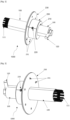
- FIG. 1 illustrates an embodiment of a grounding device according to the invention in three-quarter view.
- the grounding device comprises an electrically conductive main body 100 which has an elongated shape.
- the main body 100 can be movable in translation in the hub 210, therefore movable in translation relative to the secondary body 200.
- the fixing plate 230 allows the secondary body 200 to be fixed in a removable manner on a ventilation cover 330 of an electric rotating machine 300, in this case by means of a set of recesses 231 which allow the passage of fixing screws, rivets or other fixing means (bolting, etc.).
- blocking means are also provided to block the translational movement of the main body 100 relative to the secondary body 200 and to ensure temporary joining of the main body 100 and the secondary body 200.
- the locking means comprise a through hole 220 tapped radially in the hub 210 of the secondary body 200.
- a screw is provided that can be inserted into the tapped hole 220.
- the length of the screw is chosen so that it can come into abutment against the main body 100 when the main body 100 is inserted into the hub 210 of the secondary body 200, so as to block the translation of the main body 100 in the hub 210 of the secondary body 200, see figure 1 .
- the locking means comprise a set of at least one hole 130 passing radially through the main body 100, and arranged axially.
- the diameter of the through holes 130 and the through hole 250 are equal.
- a pin, or peg is also provided, configured to be able to be removably inserted into said assembly of at least one through hole 130 of the main body 100 and the assembly of at least one through hole 250 secured to the secondary body 200, which blocks the main body 100 in translation relative to the secondary body 200.
- the choice of a particular through hole 130 makes it possible to adjust the position of the end of the conductive fibers 110 relative to the electric rotating machine 300, thus enabling the grounding of leakage currents.
- a plurality of through holes 250 may be provided in order to increase the flexibility of use by the number of angular positions that the main body 100 can take relative to the secondary body 200.
- the locking means comprise a thread 140 arranged on an external face of the main body 100 which has a round section.
- the hub 210 of the secondary body 200 has a thread complementary to the thread 140 of the main body 100.
- the main body 100 can thus be screwed into the hub 210 of the secondary body 200, which makes it possible to perform a translational movement and thus to adjust the position of the end of the conductive fibers 110 relative to the electric rotating machine 300, thus allowing the grounding of leakage currents.
- the locking means comprise quick-tightening connectors, in particular so-called “bi-cone” or “olive” connectors, comprising a threaded male body and a corresponding female nut.
- Claw connectors can also be provided. This type of connector is known, for example, in the field of gardening or plumbing under the name of "quick connector”.
- the secondary body 200 has a thread 261.
- a nut 260 which comprises a “bi-cone” connection and whose tapping corresponds to thread 261 of the secondary body 200 makes it possible to temporarily secure the main body 100 and the secondary body 200.
- these are reversible, so as to allow the separation of the main body 100 and the secondary body 200.
- a used main body, whose conductive fibers are worn, can also be replaced with a new main body whose conductive fibers are new.
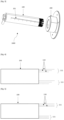
- the main body 100 has a section with radial symmetry, for example round or regular polygonal.
- the conductive fibers 110 are for example grouped into a plurality of bundles 111 of conductive fibers.
- the main body 100 comprises bundles 111 of conductive fibers arranged at the periphery of the end of the main body 100, in a circular manner.
- the conductive fibers 110 all have the same length.
- the length of the conductive fibers 110 within a bundle 111 is different, as illustrated in the figure 4 .
- the conductive fibers 110 have the same length but that this length differs from one bundle 111 to another, as illustrated in the figure 5 .
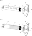
- the main body 100 comprises a set of graduations 101 inscribed thereon, as illustrated in the figure 3 , which makes it possible to adjust the position of the main body 100 relative to the secondary body 200, in particular in the event of wear of the conductive fibers 110.
- the grounding device 1000 is fixed on the ventilation cover 330 of an electric rotating machine 300 by its fixing plate 230, as illustrated in the figure 8 and the figure 9 .
- the grounding device 1000 is fixed to the ventilation cover 330 of an electric rotating machine 300 by the fixing plate 230 of the secondary body 200.
- the conductive fibers 110 are in contact with the rotating shaft 310.
- the induced bearing currents which flow through the rotating shaft 310 can thus be grounded by passing along the conductive fibers 110, the main body 100 and the grounding lug 120.
- the fixing plate 230 of the secondary body 200 can remain fixed on the ventilation cover 330. It suffices either to adjust the relative position of the main body 100 and the secondary body 200, so that the conductive fibers 110 are again in contact with the rotating shaft 310; or to replace the used main body 100 with a new main body 100, which is very quick.
Landscapes
- Engineering & Computer Science (AREA)
- Power Engineering (AREA)
- Motor Or Generator Frames (AREA)
Applications Claiming Priority (1)
| Application Number | Priority Date | Filing Date | Title |
|---|---|---|---|
| FR2302687A FR3147059B1 (fr) | 2023-03-22 | 2023-03-22 | Dispositif de mise à la terre d’une machine tournante électrique. |
Publications (1)
| Publication Number | Publication Date |
|---|---|
| EP4447294A1 true EP4447294A1 (de) | 2024-10-16 |
Family
ID=87280216
Family Applications (1)
| Application Number | Title | Priority Date | Filing Date |
|---|---|---|---|
| EP24164290.9A Pending EP4447294A1 (de) | 2023-03-22 | 2024-03-18 | Erdungsvorrichtung für eine rotierende elektrische maschine |
Country Status (2)
| Country | Link |
|---|---|
| EP (1) | EP4447294A1 (de) |
| FR (1) | FR3147059B1 (de) |
Citations (6)
| Publication number | Priority date | Publication date | Assignee | Title |
|---|---|---|---|---|
| WO1997001200A1 (en) | 1995-06-23 | 1997-01-09 | Boyanton Hugh E | Motor shaft discharge device |
| DE102007032991A1 (de) * | 2007-07-16 | 2009-01-22 | Mtu Aero Engines Gmbh | Schleifkontakteinrichtung zur Potenzialableitung an einer Werkzeugmaschinenspindel |
| DE102019206880A1 (de) * | 2018-06-14 | 2019-12-19 | Robert Bosch Gmbh | Elektrische Maschine mit einer Antriebswelle und einer Erdungseinrichtung zur elektrischen Erdung der Antriebswelle |
| US20220131448A1 (en) * | 2020-10-26 | 2022-04-28 | Illinois Tool Works Inc. | Systems and methods for threaded fasteners with grounding brush endpoints |
| WO2022135715A1 (de) * | 2020-12-23 | 2022-06-30 | Schunk Carbon Technology Gmbh | Ableitvorrichtung zur ableitung elektrischer ströme sowie maschine mit einer derartigen ableitvorrichtung |
| FR3119053A1 (fr) | 2021-01-20 | 2022-07-22 | Societe Nivolaisienne D'electrotechnique | Dispositif de mise a la terre d’une machine tournante electrique |
-
2023
- 2023-03-22 FR FR2302687A patent/FR3147059B1/fr active Active
-
2024
- 2024-03-18 EP EP24164290.9A patent/EP4447294A1/de active Pending
Patent Citations (6)
| Publication number | Priority date | Publication date | Assignee | Title |
|---|---|---|---|---|
| WO1997001200A1 (en) | 1995-06-23 | 1997-01-09 | Boyanton Hugh E | Motor shaft discharge device |
| DE102007032991A1 (de) * | 2007-07-16 | 2009-01-22 | Mtu Aero Engines Gmbh | Schleifkontakteinrichtung zur Potenzialableitung an einer Werkzeugmaschinenspindel |
| DE102019206880A1 (de) * | 2018-06-14 | 2019-12-19 | Robert Bosch Gmbh | Elektrische Maschine mit einer Antriebswelle und einer Erdungseinrichtung zur elektrischen Erdung der Antriebswelle |
| US20220131448A1 (en) * | 2020-10-26 | 2022-04-28 | Illinois Tool Works Inc. | Systems and methods for threaded fasteners with grounding brush endpoints |
| WO2022135715A1 (de) * | 2020-12-23 | 2022-06-30 | Schunk Carbon Technology Gmbh | Ableitvorrichtung zur ableitung elektrischer ströme sowie maschine mit einer derartigen ableitvorrichtung |
| FR3119053A1 (fr) | 2021-01-20 | 2022-07-22 | Societe Nivolaisienne D'electrotechnique | Dispositif de mise a la terre d’une machine tournante electrique |
Also Published As
| Publication number | Publication date |
|---|---|
| FR3147059A1 (fr) | 2024-09-27 |
| FR3147059B1 (fr) | 2025-10-03 |
Similar Documents
| Publication | Publication Date | Title |
|---|---|---|
| FR3108956A1 (fr) | Ensemble combiné d'un isolant et d'un conducteur pour des paliers à conducteur ajustable | |
| EP0878034B1 (de) | Befestigungssystem für elektrischen verbindungsschuh | |
| FR3120754A1 (fr) | Ensemble de brosse de mise à la terre | |
| FR3109036A1 (fr) | Ensemble combiné d'un isolant et d'un conducteur pour des paliers à isolant enveloppé | |
| CA2588956C (fr) | Boitier d'accessoires dans un moteur d'avion tel qu'un turboreacteur | |
| FR2866490A1 (fr) | Moteur pour direction assistee electriquement | |
| FR3133954A1 (fr) | Machine électrique comportant un manchon conducteur | |
| FR3141012A1 (fr) | Ensemble de brosse de mise à la terre | |
| FR3078208A1 (fr) | Rotor de machine electrique tournante | |
| EP4447294A1 (de) | Erdungsvorrichtung für eine rotierende elektrische maschine | |
| FR3132805A1 (fr) | Ensemble de brosse de mise à la terre | |
| FR2548472A1 (fr) | Dispositif pour le maintien et le centrage d'une rondelle porte-balais, en cours de montage, sur une machine tournante electrique a collecteur | |
| FR3090234A1 (fr) | Rotor à arbre non traversant et machine électrique tournante associée | |
| FR3119053A1 (fr) | Dispositif de mise a la terre d’une machine tournante electrique | |
| FR3017502A1 (fr) | Systeme de mise a la masse d'un arbre tournant de machine electrique | |
| FR2691848A1 (fr) | Système à bague de frottement pour la transmission de signaux électriques. | |
| FR3152664A1 (fr) | Ensemble de brosse de mise à la terre | |
| FR3150658A1 (fr) | Ensemble de brosse de mise à la terre | |
| FR3152668A1 (fr) | Ensemble de brosse de mise à la terre | |
| FR2707356A3 (fr) | Structure de joint pour l'accouplement de deux arbres tournants. | |
| FR3152663A1 (fr) | Ensemble de brosse de mise à la terre | |
| FR3152665A1 (fr) | Ensemble de brosse de mise à la terre | |
| FR3150660A1 (fr) | Ensemble de brosse de mise à la terre | |
| FR3150657A1 (fr) | Ensemble de brosse de mise à la terre | |
| WO2024189067A1 (fr) | Agencement d'un arbre et d'un carter |
Legal Events
| Date | Code | Title | Description |
|---|---|---|---|
| PUAI | Public reference made under article 153(3) epc to a published international application that has entered the european phase |
Free format text: ORIGINAL CODE: 0009012 |
|
| STAA | Information on the status of an ep patent application or granted ep patent |
Free format text: STATUS: REQUEST FOR EXAMINATION WAS MADE |
|
| 17P | Request for examination filed |
Effective date: 20240318 |
|
| AK | Designated contracting states |
Kind code of ref document: A1 Designated state(s): AL AT BE BG CH CY CZ DE DK EE ES FI FR GB GR HR HU IE IS IT LI LT LU LV MC ME MK MT NL NO PL PT RO RS SE SI SK SM TR |