EP0660914B1 - Chambre de vaporisation munie d'une couche anti-calefaction - Google Patents
Chambre de vaporisation munie d'une couche anti-calefaction Download PDFInfo
- Publication number
- EP0660914B1 EP0660914B1 EP94922915A EP94922915A EP0660914B1 EP 0660914 B1 EP0660914 B1 EP 0660914B1 EP 94922915 A EP94922915 A EP 94922915A EP 94922915 A EP94922915 A EP 94922915A EP 0660914 B1 EP0660914 B1 EP 0660914B1
- Authority
- EP
- European Patent Office
- Prior art keywords
- fibers
- steam
- layer
- metal plate
- generating apparatus
- Prior art date
- Legal status (The legal status is an assumption and is not a legal conclusion. Google has not performed a legal analysis and makes no representation as to the accuracy of the status listed.)
- Expired - Lifetime
Links
Images
Classifications
-
- D—TEXTILES; PAPER
- D06—TREATMENT OF TEXTILES OR THE LIKE; LAUNDERING; FLEXIBLE MATERIALS NOT OTHERWISE PROVIDED FOR
- D06F—LAUNDERING, DRYING, IRONING, PRESSING OR FOLDING TEXTILE ARTICLES
- D06F75/00—Hand irons
- D06F75/08—Hand irons internally heated by electricity
- D06F75/10—Hand irons internally heated by electricity with means for supplying steam to the article being ironed
- D06F75/14—Hand irons internally heated by electricity with means for supplying steam to the article being ironed the steam being produced from water in a reservoir carried by the iron
- D06F75/18—Hand irons internally heated by electricity with means for supplying steam to the article being ironed the steam being produced from water in a reservoir carried by the iron the water being fed slowly, e.g. drop by drop, from the reservoir to a steam generator
-
- F—MECHANICAL ENGINEERING; LIGHTING; HEATING; WEAPONS; BLASTING
- F22—STEAM GENERATION
- F22B—METHODS OF STEAM GENERATION; STEAM BOILERS
- F22B1/00—Methods of steam generation characterised by form of heating method
- F22B1/28—Methods of steam generation characterised by form of heating method in boilers heated electrically
- F22B1/287—Methods of steam generation characterised by form of heating method in boilers heated electrically with water in sprays or in films
-
- F—MECHANICAL ENGINEERING; LIGHTING; HEATING; WEAPONS; BLASTING
- F28—HEAT EXCHANGE IN GENERAL
- F28F—DETAILS OF HEAT-EXCHANGE AND HEAT-TRANSFER APPARATUS, OF GENERAL APPLICATION
- F28F19/00—Preventing the formation of deposits or corrosion, e.g. by using filters or scrapers
- F28F19/02—Preventing the formation of deposits or corrosion, e.g. by using filters or scrapers by using coatings, e.g. vitreous or enamel coatings
-
- F—MECHANICAL ENGINEERING; LIGHTING; HEATING; WEAPONS; BLASTING
- F28—HEAT EXCHANGE IN GENERAL
- F28F—DETAILS OF HEAT-EXCHANGE AND HEAT-TRANSFER APPARATUS, OF GENERAL APPLICATION
- F28F2245/00—Coatings; Surface treatments
- F28F2245/02—Coatings; Surface treatments hydrophilic
Definitions
- the present invention relates to the technical field apparatus for vaporizing fluids and in particular field of steam irons.
- the present invention relates on the one hand to a layer anti-calefaction provided in a vaporization chamber, and on the other hand a method of manufacturing such a layer also intended for spraying an ironing liquid, usually the occurrence of water.
- the various solutions provided by the prior art do not allow however, to sufficiently limit the heat build-up in the vaporization.
- the caulking usually occurs by bringing a liquid on a very hot surface. Spraying a small amount of liquid on such a surface causes the appearance of drops moving randomly on said surface and which are only vaporized after a time interval relatively large. Contact between a drop of liquid and the surface hot generates steam which lodges between said surface and the base of said drop directed towards this surface. The vapor cushion thus formed promotes displacement of the drop on the hot surface and considerably reduces the vaporization.
- tissue fibers used in the prior art are maintained in place through various mechanical means. These latter significantly increase the complexity of manufacturing or realization of said vaporization layers. Otherwise, this more complicated realization is linked to the use a larger number of pieces. These different factors are the source of a significant manufacturing cost. this is especially the case when manufacturing iron soles ironing with a vaporization chamber fitted with a such coating.
- the object assigned to the invention therefore aims to remedy the various drawbacks listed above and to provide a vapor generating device whose spray quality is improved.
- the object of the present invention is to provide a steam generating device comprising a spraying with a spraying bottom allowing quickly vaporize a liquid by limiting the phenomenon of caulking.
- the object of the present invention also aims to provide a steam generating device which exhibits, in addition to a reduction in the phenomenon of heat build-up, a background almost insensitive to possible acidity of the liquid intended to be vaporized.
- Another object of the present invention is to provide a bottom of a mechanically resistant spray chamber and secured with an iron soleplate for example, without the use of additional mechanical means.
- Another object of the present invention is to provide a steam generating device including the vaporization has an insensitive anti-caulking layer thermal shock and adhering well to the bottom of said chamber so as to ensure optimal heat transfer.
- the invention also aims to provide a method simple and effective production of an anti-calefaction layer in a vaporization chamber of a device for generating steam.
- An additional object of the invention aims to provide a generation device efficient and reliable steam whose manufacturing cost is significantly reduced and whose lifespan is increased at the same time.
- a device for generation of steam comprising a heating means in thermal relation with a vaporization chamber, a liquid reservoir communicating with the vaporization chamber, which has a bottom against which the liquid intended to be evaporated, said bottom comprising a zone defining a surface layer of a thermal conductive material inside the vaporization chamber, characterized in that the layer has over its entire surface of partially hydrophilic and thermally insulating fibers and locally embedded in the thermal conductive material of the layer.
- the objects assigned to the invention are also achieved by means of a process for producing a bottom of a vaporization chamber consisting of use thermally insulating and hydrophilic fibers and a material thermally conductive aluminum type characterized in that it consists of intimately bond the fibers with the bottom in a layer of a surface area of said bottom, so as to ensure a thermal transfer between the material thermally conductive, constituting the bottom, and the layer, said material partially impregnating said fibers.
- the steam generating device (not shown in the figures) has a vaporization chamber (not shown in the figures), into which the liquid to vaporize, from a tank. This last includes for example an exit to the right of an impact zone on a bottom 3 of the vaporization chamber.
- the bottom 3 is made of a thermally conductive material 2 and metalogical preference.
- the material 2 is either aluminum, an alloy comprising aluminum.
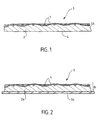
- the bottom 3 has fibers 1 in a surface area woven, hydrophilic and insulating properties thermally at least partially and locally embedded in the material 2, constituting the bottom 3 and therefore a surface layer A of said bottom 3.
- the surface area thus produced extends over at least part of at least one wall of the vaporization chamber, said wall facing a spray liquid inlet port.
- Layer A therefore partly comprises fibers 1 to less partially and locally impregnated with the material constituting layer A.
- the latter is well obviously located inside a vaporization, opposite an orifice intended to inject a liquid in said vaporization chamber.
- Fibers 1 penetrate at least partially and locally in layer A. Fibers 1 are of this way integrated in places in the constituent material 2 from the bottom 3.
- the latter therefore comprises a surface layer A in which are locally embedded fibers 1 arranged between they for example in meshes.
- the fibers 1 are overmolded in layer A.
- the fibers 1 are partially embedded in said material 2 and partly visible. Some are on a portion of their length is completely embedded in the material 2, or partially embedded in material 2, either completely visible and free from the material 2. Others are embedded in material 2 for a large part of their length, or completely freed from said material 2.
- the bottom 3 is thus secured to the fibers 1 in a surface area corresponding to layer A.
- the assembly thus exhibits rigidity and solidity adapted to the mechanical constraints of the expansion type and contractions due to temperature variations.
- Layer A heterogeneous thus absorbs shocks satisfactorily very frequent thermal in an iron soleplate.
- said surface area consists of two materials, one thermally insulating, of the fiber type ceramics, the other thermally conductive of the type aluminum for example.
- Impregnation of fibers 1 made of ceramic material causes a slight drop in temperature on the surface against which is brought the liquid to be vaporized by relative to the temperature of the material 2 constituting the bottom 3.
- Layer A thus acts as a light heat shield.
- the heterogeneous layer A also has a surface, on which the liquid intended to be vaporized is led, it is largely made up of fibers 1 hydrophilic, preferably woven, which absorb and at least partially diffuse the liquid and / or soak up of said liquid in said layer A.
- the temperature drop at the bottom surface 3 and the hydrophilic properties and wetting agents help reduce the phenomenon of heat build-up. As a result the vaporization is improved and accelerated.
- layer A is consisting of an additional metal plate B linked intimately to an iron sole for example, which is thermally conductive.
- Plate B for example made of aluminum, is maintained in thermal and mechanical contact with the sole 3a by crimping or any other means.
- the sole 3a is an iron sole with iron, and the plate B is molded onto said sole.
- the anti-caulking layer thus produced on the bottom 3 inside the vaporization chamber has preferably hydrophilic woven and insulating fibers 1 thermally.
- the fibers 1 used to partially produce the layer A in the vaporization chamber are, according to a variant of realization of the device, according to the invention, fibers hydrophilic, mineral hydrophilic or synthetic ceramics hydrophilic.
- fiber yarns of glass or composed of a mixture of metal and silica are perfectly suitable, as are fibers carbon or organic.
- the device steam generation involves a weaving of at least two different types of fibers.
- the fibers are used nonwoven.
- the present invention also relates to a method of production of a bottom 3 of a vaporization chamber of a steam generating device.
- the process consists of use thermally insulating and hydrophilic fibers 1 as well as a thermally conductive material, of the type aluminum to make a surface layer A of a bottom 3.
- the method consists in intimately bonding the fibers 1 with the bottom 3 in a layer A of a surface area of said bottom 3, so as to ensure heat transfer between said bottom 3 and layer A.
- the fiber fabric 1 is placed inside a mold before injection of a molten material 2.
- the link intimate mechanics between the fiber fabric 1 and the bottom 3 is thus produced directly by overmolding.
- the latter permeates at least partially and locally the fibers 1 in a superficial layer A of the bottom 3.
- the mechanical fixing of the fibers 1 is thus reached and ensured.
- the material 2 also has a surface 4 located opposite the layer A which performs the functions of an iron soleplate iron.
- the intimate connection between the fibers 1 and bottom 3 is done through a metallic plate B used as interface between fibers 1 and the sole 3a.
- One of the process steps consists in intimately bind the fibers 1 with the metal plate B by example by overmolding.
- the step of overmolding the plate B on the sole 3a can thus be advantageously replaced by a step of crimping or bonding.
- the sole 3a is preferably used directly as an iron soleplate.
- the advantage of a steam generator according to the invention and manufactured in accordance with the realization of a vaporization chamber of said device, is that it improves the vaporization yield, especially in a steam iron, without as much increase the manufacturing cost.
- Another advantage of a device for generating steam according to the invention is an increased screw life with respect to existing vaporization devices.
- the invention finds its industrial application in the field of devices for producing steam and including steam irons.
Landscapes
- Engineering & Computer Science (AREA)
- Physics & Mathematics (AREA)
- Thermal Sciences (AREA)
- Mechanical Engineering (AREA)
- General Engineering & Computer Science (AREA)
- Textile Engineering (AREA)
- Life Sciences & Earth Sciences (AREA)
- Sustainable Development (AREA)
- Sustainable Energy (AREA)
- Irons (AREA)
Description
- la figure 1 représente une vue transversale en coupe, d'un fond d'une chambre de vaporisation d'un dispositif de génération de vapeur conforme à l'invention.
- la figure 2 représente une vue transversale en coupe d'une variante de réalisation d'un fond d'une chambre de vaporisation.
Claims (15)
- Dispositif de génération de vapeur comportant un moyen de chauffe en relation thermique avec une chambre de vaporisation, un réservoir de liquide communiquant avec la chambre de vaporisation, laquelle comporte un fond (3) contre lequel est dirigé le liquide destiné à être évaporé, ledit fond (3) comportant une zone définissant une couche (A) superficielle d'un matériau conducteur thermique à l'intérieur de la chambre de vaporisation, caractérisé en ce que la couche (A) présente sur toute sa surface des fibres (1) hydrophiles et thermiquement isolantes partiellement et localement noyées dans le matériau conducteur thermique de la couche (A).
- Dispositif de génération de vapeur selon la revendication 1 caractérisé en ce que les fibres (1) hydrophiles sont surmoulées dans la couche (A) superficielle.
- Dispositif de génération de vapeur selon la revendication 1 caractérisé en ce que la couche (A) est constituée d'une plaque (B) métallique additionnelle liée intimement à une semelle (3a), laquelle est thermiquement conductrice.
- Dispositif de génération de vapeur selon la revendication 3 caractérisé en ce que la liaison mécanique de maintien entre la plaque (B) métallique et les fibres (1) hydrophiles est obtenue par pressage ou écrasement.
- Dispositif de génération de vapeur selon l'une des revendications 1 à 4 caractérisé en ce qu'il comporte des fibres (1) hydrophiles tissées et isolantes thermiquement.
- Dispositif de génération de vapeur selon l'une des revendications 1 à 5 caractérisé en ce qu'il comporte des fibres (1) céramiques, minérales ou synthétiques.
- Dispositif de génération de vapeur selon la revendication 6 caractérisé en ce qu'il comporte un tissage d'au moins deux types de fibres (1) différents.
- Fer à repasser à vapeur comportant un dispositif conforme à l'une des revendications 1 à 7.
- Procédé de réalisation d'un fond (3) d'une chambre de vaporisation consistant à utiliser des fibres (1) isolantes thermiquement et hydrophiles ainsi qu'un matériau thermiquement conducteur de type aluminium caractérisé en ce qu'il consiste à lier intimement les fibres (1) avec le fond (3) dans une couche (A) d'une zone superficielle dudit fond (3), de manière à assurer un transfert thermique entre le matériau thermiquement conducteur, constitutif du fond (3), et la couche (A), ledit matériau imprégnant partiellement lesdites fibres (1).
- Procédé selon la revendication 9 caractérisé en ce qu'il consiste à lier intimement les fibres (1) avec le fond (3) par l'intermédiaire d'une plaque (B) métallique utilisée comme interface entre les fibres (1) et une semelle (3a).
- Procédé selon la revendication 10 caractérisé en ce qu'il consiste à lier intimement les fibres (1) avec la plaque (B) métallique par pressage ou écrasement.
- Procédé selon la revendication 10 caractérisé en ce qu'il consiste à lier intimement les fibres (1) avec la plaque (B) métallique par surmoulage.
- Procédé selon l'une des revendications 10 à 12 caractérisé en ce qu'il consiste à lier intimement la plaque (B) métallique avec la semelle (3a) de la chambre de vaporisation par surmoulage.
- Procédé selon l'une des revendications 10 à 12 caractérisé en ce qu'il consiste à lier intimement la plaque métallique avec la semelle (3a) par sertissage.
- Procédé selon la revendication 9 caractérisé en ce qu'il consiste à lier intimement les fibres (1) avec le fond (3) directement par surmoulage sur ce dernier, de manière à ce que le matériau constitutif du fond (3) imprègne au moins partiellement et localement lesdites fibres (1) dans une couche (A) superficielle dudit fond (3).
Applications Claiming Priority (3)
| Application Number | Priority Date | Filing Date | Title |
|---|---|---|---|
| FR9308988 | 1993-07-16 | ||
| FR9308988A FR2707732B1 (fr) | 1993-07-16 | 1993-07-16 | Chambre de vaporisation munie d'une couche anti-caléfaction. |
| PCT/FR1994/000877 WO1995002787A1 (fr) | 1993-07-16 | 1994-07-13 | Chambre de vaporisation munie d'une couche anti-calefaction |
Publications (2)
| Publication Number | Publication Date |
|---|---|
| EP0660914A1 EP0660914A1 (fr) | 1995-07-05 |
| EP0660914B1 true EP0660914B1 (fr) | 1998-01-14 |
Family
ID=9449482
Family Applications (1)
| Application Number | Title | Priority Date | Filing Date |
|---|---|---|---|
| EP94922915A Expired - Lifetime EP0660914B1 (fr) | 1993-07-16 | 1994-07-13 | Chambre de vaporisation munie d'une couche anti-calefaction |
Country Status (5)
| Country | Link |
|---|---|
| US (1) | US5592764A (fr) |
| EP (1) | EP0660914B1 (fr) |
| DE (1) | DE69407941T2 (fr) |
| FR (1) | FR2707732B1 (fr) |
| WO (1) | WO1995002787A1 (fr) |
Families Citing this family (9)
| Publication number | Priority date | Publication date | Assignee | Title |
|---|---|---|---|---|
| IT1294305B1 (it) * | 1997-08-05 | 1999-03-24 | Elettrotecnica B C S P A | Ferro da stiro |
| FR2806427B1 (fr) | 2000-03-15 | 2002-04-26 | Seb Sa | Revetement de chambre a vapeur de fer a repasser |
| DE50304688D1 (de) * | 2002-10-24 | 2006-09-28 | Murjahn Amphibolin Werke | Wässrige mineralische beschichtungsmittel, schichten auf deren basis, ihre herstellung und ihre verwendung |
| EP2068075A2 (fr) * | 2007-10-05 | 2009-06-10 | Koninklijke Philips Electronics N.V. | Dispositif générateur de vapeur doté d'un revêtement hydrophile |
| US10247483B2 (en) * | 2008-09-23 | 2019-04-02 | Oxycom Beheer B.V. | Evaporative cooling device |
| GB0901855D0 (en) | 2009-02-05 | 2009-03-11 | Strix Ltd | Electric steam generation |
| TR201701724A2 (tr) * | 2017-02-06 | 2018-08-27 | Arcelik As | Bi̇r su kaynatma kazani i̇çeren bi̇r ütü |
| CN111032953B (zh) | 2017-06-16 | 2023-04-18 | 品谱公司 | 具有预热腔室和过滤器的蒸汽发生器 |
| FR3160228B1 (fr) | 2024-03-15 | 2026-05-08 | Seb Sa | Ensemble de génération de vapeur pour appareil domestique |
Family Cites Families (13)
| Publication number | Priority date | Publication date | Assignee | Title |
|---|---|---|---|---|
| US2683320A (en) * | 1948-11-05 | 1954-07-13 | Westinghouse Electric Corp | Steam iron |
| FR1134066A (fr) * | 1954-07-15 | 1957-04-05 | Thomson Houston Comp Francaise | Perfectionnements apportés aux fers à repasser électriques à vapeur |
| US2792652A (en) * | 1955-11-09 | 1957-05-21 | John P Thornton | Steam iron |
| FR1359794A (fr) * | 1961-11-17 | 1964-04-30 | Casco Products Corp | Fer à repasser à vapeur |
| US3218741A (en) * | 1963-09-03 | 1965-11-23 | Hoover Co | Coating for steam iron flash boiler |
| US3499237A (en) * | 1966-05-23 | 1970-03-10 | Hoover Co | Coating for steam iron flash boiler |
| GB1176429A (en) * | 1967-10-24 | 1970-01-01 | Westinghouse Electric Corp | Steam Chamber Coatings for Steam Irons and the like |
| DE3006783A1 (de) * | 1980-02-22 | 1981-08-27 | Ritter Aluminium Gmbh, 7300 Esslingen | Buegeleisensohle fuer ein dampf-buegeleisen |
| DD151194A1 (de) * | 1980-06-13 | 1981-10-08 | Guenter Diekers | Verfahren zur verdampfungsraumbeschichtung von dampf-buegelvorrichtungen |
| JPS60160999A (ja) * | 1984-02-02 | 1985-08-22 | 松下電器産業株式会社 | スチ−ムアイロン |
| US5060406A (en) * | 1989-10-25 | 1991-10-29 | U.S. Philips Corporation | Steam iron having a hydrophilic acid resistant steam changer |
| DE4221434A1 (de) * | 1992-06-30 | 1994-01-05 | Siemens Ag | Herstellverfahren für einen Speicherkondensator |
| FR2696197B1 (fr) * | 1992-09-29 | 1994-11-25 | Seb Sa | Fer à repasser à chambre de vaporisation pourvue d'une grille de répartition d'eau. |
-
1993
- 1993-07-16 FR FR9308988A patent/FR2707732B1/fr not_active Expired - Fee Related
-
1994
- 1994-07-13 US US08/397,058 patent/US5592764A/en not_active Expired - Fee Related
- 1994-07-13 WO PCT/FR1994/000877 patent/WO1995002787A1/fr not_active Ceased
- 1994-07-13 DE DE69407941T patent/DE69407941T2/de not_active Expired - Fee Related
- 1994-07-13 EP EP94922915A patent/EP0660914B1/fr not_active Expired - Lifetime
Also Published As
| Publication number | Publication date |
|---|---|
| US5592764A (en) | 1997-01-14 |
| FR2707732A1 (fr) | 1995-01-20 |
| DE69407941T2 (de) | 1998-06-10 |
| WO1995002787A1 (fr) | 1995-01-26 |
| EP0660914A1 (fr) | 1995-07-05 |
| FR2707732B1 (fr) | 1995-08-25 |
| DE69407941D1 (de) | 1998-02-19 |
Similar Documents
| Publication | Publication Date | Title |
|---|---|---|
| EP0592334B1 (fr) | Fer à repasser à chambre de vaporisation pourvue d'une grille de répartition d'eau | |
| FR2707732A1 (fr) | Chambre de vaporisation munie d'une couche anti-caléfaction. | |
| FR2569237A1 (fr) | Dispositif de protection thermique resistant a l'ablation et aux vibrations, et un procede de fabrication | |
| EP0555159B1 (fr) | Elément chauffant à structure sandwich et appareil éléctroménager, du type fer à repasser à vapeur, comportant un tel élément | |
| WO2020127851A1 (fr) | Appareil de coiffure a vapeur | |
| EP4399993A2 (fr) | Appareil de coiffure a vapeur | |
| FR2677442A1 (fr) | Chemise de tube de canon en materiau composite, son procede de fabrication, et tube de canon muni d'une telle chemise. | |
| EP0625609A1 (fr) | Fer à repasser et procédé de fabrication d'un tel fer | |
| EP2808439B1 (fr) | Appareil de repassage à la vapeur | |
| EP2758584A1 (fr) | Fer a repasser comportant un dispositif pour projeter des gouttelettes de liquide a l'exterieur de la surface couverte par la semelle | |
| EP0998603B1 (fr) | Fer comportant deux moyens de chauffe avec un mode d'asservissement en temperature particulier | |
| EP0576321A1 (fr) | Dispositif de protection antifeu en matériau souple endothermique | |
| CA2736025C (fr) | Systeme de repassage | |
| FR2489859A1 (fr) | Fer a repasser electrique a vapeur | |
| FR3067725B1 (fr) | Appareil pour le traitement du linge comportant un generateur de vapeur a vaporisation instantanee | |
| FR2791125A1 (fr) | Four de cuisson avec generateur de vapeur chauffe au gaz | |
| EP1264028B1 (fr) | Revetement de chambre a vapeur de fer a repasser | |
| EP0556721A1 (fr) | Semelle de fer à repasser et son procédé de fabrication | |
| EP1052725B1 (fr) | Surface réfléchissant les ondes électromagnétiques et procédé pour sa réalisation | |
| FR2538507A1 (fr) | Procede pour la fabrication d'une couche d'ablation traversee par un mat | |
| EP0891118B1 (fr) | Elément chauffant et appareil électroménager, notamment fer à repasser à vapeur, comportant un tel élément et procédé d'obtention du fer à repasser | |
| EP0713937B1 (fr) | Fer à repasser comportant une semelle améliorée | |
| FR3060032A1 (fr) | Appareil de repassage a la vapeur comprenant une base generatrice de vapeur et un fer a repasser relies entre eux par un conduit | |
| FR2807365A1 (fr) | Archet de pantographe avec etrier en materiau composite | |
| FR2616554A1 (fr) | Miroir comprenant une matiere carbonee renforcee par des fibres de carbone |
Legal Events
| Date | Code | Title | Description |
|---|---|---|---|
| PUAI | Public reference made under article 153(3) epc to a published international application that has entered the european phase |
Free format text: ORIGINAL CODE: 0009012 |
|
| 17P | Request for examination filed |
Effective date: 19950308 |
|
| AK | Designated contracting states |
Kind code of ref document: A1 Designated state(s): DE GB IT NL |
|
| RAP1 | Party data changed (applicant data changed or rights of an application transferred) |
Owner name: SEB S.A. |
|
| 17Q | First examination report despatched |
Effective date: 19960723 |
|
| GRAG | Despatch of communication of intention to grant |
Free format text: ORIGINAL CODE: EPIDOS AGRA |
|
| GRAG | Despatch of communication of intention to grant |
Free format text: ORIGINAL CODE: EPIDOS AGRA |
|
| GRAH | Despatch of communication of intention to grant a patent |
Free format text: ORIGINAL CODE: EPIDOS IGRA |
|
| GRAH | Despatch of communication of intention to grant a patent |
Free format text: ORIGINAL CODE: EPIDOS IGRA |
|
| GRAA | (expected) grant |
Free format text: ORIGINAL CODE: 0009210 |
|
| AK | Designated contracting states |
Kind code of ref document: B1 Designated state(s): DE GB IT NL |
|
| REF | Corresponds to: |
Ref document number: 69407941 Country of ref document: DE Date of ref document: 19980219 |
|
| GBT | Gb: translation of ep patent filed (gb section 77(6)(a)/1977) |
Effective date: 19980212 |
|
| ITF | It: translation for a ep patent filed | ||
| PGFP | Annual fee paid to national office [announced via postgrant information from national office to epo] |
Ref country code: DE Payment date: 19980612 Year of fee payment: 5 |
|
| PGFP | Annual fee paid to national office [announced via postgrant information from national office to epo] |
Ref country code: GB Payment date: 19980706 Year of fee payment: 5 |
|
| PGFP | Annual fee paid to national office [announced via postgrant information from national office to epo] |
Ref country code: NL Payment date: 19980731 Year of fee payment: 5 |
|
| PLBE | No opposition filed within time limit |
Free format text: ORIGINAL CODE: 0009261 |
|
| STAA | Information on the status of an ep patent application or granted ep patent |
Free format text: STATUS: NO OPPOSITION FILED WITHIN TIME LIMIT |
|
| 26N | No opposition filed | ||
| PG25 | Lapsed in a contracting state [announced via postgrant information from national office to epo] |
Ref country code: GB Free format text: LAPSE BECAUSE OF NON-PAYMENT OF DUE FEES Effective date: 19990713 |
|
| PG25 | Lapsed in a contracting state [announced via postgrant information from national office to epo] |
Ref country code: NL Free format text: LAPSE BECAUSE OF NON-PAYMENT OF DUE FEES Effective date: 20000201 |
|
| GBPC | Gb: european patent ceased through non-payment of renewal fee |
Effective date: 19990713 |
|
| NLV4 | Nl: lapsed or anulled due to non-payment of the annual fee |
Effective date: 20000201 |
|
| PG25 | Lapsed in a contracting state [announced via postgrant information from national office to epo] |
Ref country code: DE Free format text: LAPSE BECAUSE OF NON-PAYMENT OF DUE FEES Effective date: 20000503 |
|
| PG25 | Lapsed in a contracting state [announced via postgrant information from national office to epo] |
Ref country code: IT Free format text: LAPSE BECAUSE OF NON-PAYMENT OF DUE FEES;WARNING: LAPSES OF ITALIAN PATENTS WITH EFFECTIVE DATE BEFORE 2007 MAY HAVE OCCURRED AT ANY TIME BEFORE 2007. THE CORRECT EFFECTIVE DATE MAY BE DIFFERENT FROM THE ONE RECORDED. Effective date: 20050713 |