EP0660351B1 - Verbesserte strombegrenzende Schmelzsicherung und dropout Sicherungshalter - Google Patents
Verbesserte strombegrenzende Schmelzsicherung und dropout Sicherungshalter Download PDFInfo
- Publication number
- EP0660351B1 EP0660351B1 EP94309367A EP94309367A EP0660351B1 EP 0660351 B1 EP0660351 B1 EP 0660351B1 EP 94309367 A EP94309367 A EP 94309367A EP 94309367 A EP94309367 A EP 94309367A EP 0660351 B1 EP0660351 B1 EP 0660351B1
- Authority
- EP
- European Patent Office
- Prior art keywords
- current
- fuse
- wire
- fusible element
- fuseholder
- Prior art date
- Legal status (The legal status is an assumption and is not a legal conclusion. Google has not performed a legal analysis and makes no representation as to the accuracy of the status listed.)
- Expired - Lifetime
Links
Images


Classifications
-
- H—ELECTRICITY
- H01—ELECTRIC ELEMENTS
- H01H—ELECTRIC SWITCHES; RELAYS; SELECTORS; EMERGENCY PROTECTIVE DEVICES
- H01H85/00—Protective devices in which the current flows through a part of fusible material and this current is interrupted by displacement of the fusible material when this current becomes excessive
- H01H85/02—Details
- H01H85/36—Means for applying mechanical tension to fusible member
-
- H—ELECTRICITY
- H01—ELECTRIC ELEMENTS
- H01H—ELECTRIC SWITCHES; RELAYS; SELECTORS; EMERGENCY PROTECTIVE DEVICES
- H01H31/00—Air-break switches for high tension without arc-extinguishing or arc-preventing means
- H01H31/02—Details
- H01H31/12—Adaptation for built-in fuse
- H01H31/122—Fuses mounted on, or constituting the movable contact parts of, the switch
- H01H31/127—Drop-out fuses
-
- H—ELECTRICITY
- H01—ELECTRIC ELEMENTS
- H01H—ELECTRIC SWITCHES; RELAYS; SELECTORS; EMERGENCY PROTECTIVE DEVICES
- H01H85/00—Protective devices in which the current flows through a part of fusible material and this current is interrupted by displacement of the fusible material when this current becomes excessive
- H01H85/02—Details
- H01H85/04—Fuses, i.e. expendable parts of the protective device, e.g. cartridges
- H01H85/05—Component parts thereof
- H01H85/055—Fusible members
- H01H85/12—Two or more separate fusible members in parallel
-
- H—ELECTRICITY
- H01—ELECTRIC ELEMENTS
- H01H—ELECTRIC SWITCHES; RELAYS; SELECTORS; EMERGENCY PROTECTIVE DEVICES
- H01H85/00—Protective devices in which the current flows through a part of fusible material and this current is interrupted by displacement of the fusible material when this current becomes excessive
- H01H85/02—Details
- H01H85/38—Means for extinguishing or suppressing arc
-
- C—CHEMISTRY; METALLURGY
- C08—ORGANIC MACROMOLECULAR COMPOUNDS; THEIR PREPARATION OR CHEMICAL WORKING-UP; COMPOSITIONS BASED THEREON
- C08L—COMPOSITIONS OF MACROMOLECULAR COMPOUNDS
- C08L2201/00—Properties
- C08L2201/12—Shape memory
-
- H—ELECTRICITY
- H01—ELECTRIC ELEMENTS
- H01H—ELECTRIC SWITCHES; RELAYS; SELECTORS; EMERGENCY PROTECTIVE DEVICES
- H01H85/00—Protective devices in which the current flows through a part of fusible material and this current is interrupted by displacement of the fusible material when this current becomes excessive
- H01H2085/0004—Protective devices in which the current flows through a part of fusible material and this current is interrupted by displacement of the fusible material when this current becomes excessive making use of shape-memory material
-
- H—ELECTRICITY
- H01—ELECTRIC ELEMENTS
- H01H—ELECTRIC SWITCHES; RELAYS; SELECTORS; EMERGENCY PROTECTIVE DEVICES
- H01H85/00—Protective devices in which the current flows through a part of fusible material and this current is interrupted by displacement of the fusible material when this current becomes excessive
- H01H85/02—Details
- H01H85/0241—Structural association of a fuse and another component or apparatus
- H01H2085/0258—Structural association of a fuse or a fuse holder with a bimetallic element
Definitions
- the present invention relates generally to a fuse assembly according to the preamble of claim 1, as for example known from US-A-4123738. More particularly, the invention relates to current limiting fuses and to dropout style fuseholders. Still more particularly, the invention relates to a current limiting dropout fuseholder which includes multiple current paths and which shifts the current flowing through the fuseholder between the various paths to aid in the dropout process, the fuseholder being particularly adapted for installation in the industry-standard interchangeable cutout mountings that are presently used with expulsion fuses.
- a fuse is a current interrupting device which protects a circuit by means of a current-responsive fusible element.
- a current-responsive fusible element melts, thereby opening the circuit. After having interrupted an overcurrent, the fuse must be located and replaced in order to restore service.
- Fuses are typically employed in the electrical utility industry to protect distribution transformers, cables, capacitor banks and other equipment from damaging overcurrents.
- the fuses are arranged to disconnect the faulted equipment or circuit promptly from its source of supply before damage can occur.
- two basic types of fuses are employed, the expulsion fuse and the current limiting fuse.
- An expulsion fuse typically employs a relatively short length of a fusible element (within what is commonly termed a "fuselink") contained within a tubular enclosure that is part of a larger assembly known as a "fuseholder".
- the enclosure used in the expulsion type fuse is lined with an organic material, such as bone fiber. Interruption of an overcurrent takes place within the fuse by the deionizing and explosive action of the gases which are liberated when the liner is exposed to the heat of the arc that is created when the fusible element melts in response to the overcurrent.
- expulsion-type fuse The operation of the expulsion-type fuse is characterized by loud noise and violent emission of gases, flame and burning debris, all of which pose a danger to personnel who may be in close proximity to the fuse when it operates. Because of its violent mode of operation, this type of fuse has generally been restricted to outdoor usage only. Even when employed outdoors, the expulsion fuse must be mounted well away from the equipment it is intended to protect, as well as other equipment, due to the explosive nature of its operation and its tendency to inject ionized gases into insulating spaces. Further, expulsion fuses mounted on distribution system poles have been known to initiate grass fires resulting from the flaming debris which may be expelled.
- expulsion type fuse requires 1/2 or sometimes 1 full cycle of current before the fuse clears a high current fault.
- the equipment the fuse is designed to protect must endure the full available fault current that is allowed to pass through the fuse to the equipment.
- Potentially damaging energy that will be dissipated in the equipment will be proportional to the formula I 2 T, where I is the magnitude of the overcurrent and T is the time that the current condition exists.
- I is the magnitude of the overcurrent
- T is the time that the current condition exists.
- the high current that an expulsion fuse allows to flow prior to its interruption at a system current zero tends to cause bothersome voltage dips upon the network, causing lights to flicker and sensitive computers and electronic equipment to suffer.
- expulsion fuses may not clear the overcurrent condition soon enough to prevent sectionalizing fuses, reclosers or other protective relays and circuit devices from also sensing the overcurrent and responding by temporarily and sometimes permanently disconnecting other portions of the network. Additionally, the increased demand for electrical service has led to lower impedance distribution networks and the need for greater interrupting capabilities, capabilities which sometimes exceed those available through the use of expulsion fuses.
- the limited interrupting capacity of expulsion-type fuses coupled with their potentially dangerous mode of operation, their unsuitability for use within buildings or enclosures, their relatively slow clearing time, as well as other factors, prompted the development of the current limiting fuses.
- the current-limiting fuse has at least three features that have made it extremely desirable for use by the utilities:
- a current-limiting fuse typically consists of one or more fusible elements of silver wire or ribbon which are electrically connected at their ends to a pair of electrical terminations.
- the fusible elements require a minimum element length for proper fault current interrupting performance, and also require sufficient element cross sectional area in order to properly carry the normal or steady-state system currents.
- the assembly -- consisting of the fusible element and end terminations -- is placed in a tubular housing that is made of a highly temperature-resistant material, and the housing is then typically filled with high-purity silica sand and sealed. Terminals on the ends of the housing interconnect the fuse with the distribution network. The entire assembly is generally known as a current-limiting fuse.
- the fusible element of a current limiting fuse melts almost instantaneously over its full length. If segments having reduced cross sectional areas are formed in the element, the element melts initially at these reduced area segments, followed by melting of the remaining length of the element. The resulting arc rapidly loses heat energy to the surrounding sand. This energy melts or fuses the sand surrounding the element into a glass-like tunnel structure called a "fulgurite.” The rapid loss of heat energy and the confinement of the arc by the molten glass fulgurite literally chokes off the current to a relatively small value. The current is quickly reduced to low levels, brought into phase with the system voltage and interrupted at the earliest-occurring current zero of the in-phase current.
- a metallic ribbon as the high magnitude fusible element is quite common in higher current rated fuses.
- the ribbon form has the advantage over wire elements by having a larger surface area for thermal conductivity and radiation to the adjacent filler material. Consequently, for a given volume of conductor material, a ribbon element can have a higher steady-state ampere rating than a wire element, as well as improved interrupting characteristics. Ribbon also has the distinct advantage of lending itself to modification with perforations or notches in order to reduce its cross sectional area in order to provide the desired melt characteristics and exact arc-voltage generation control. When a current-limiting fuse using ribbon-type elements encounters a high-fault current, the ribbon portions having reduced cross-sectional area are heated rapidly to the melting point of the ribbon.
- a cutout consists of a mounting having an insulating support designed to be mounted on a utility pole or crossarm and having a pair of spaced-apart terminals which are designed to receive and electrically engage a fuseholder, a switch assembly, or a combination thereof. When installed, the fuseholder or switch bridges the "gate" between the terminals of the cutout mounting.
- fuse cutout usually refers to the combination of a cutout mounting, as described above, with a fuseholder.
- the fuseholder that is most typically employed in a fuse cutout is designed to be easily disengaged from the terminals of the cutout.
- One such fuseholder is the "dropout” type which is designed such that, upon actuation of the fuse, one end of the fuseholder becomes disengaged from the cutout mounting. When this occurs, the unrestrained end of the fuseholder rotates down and away from its normal bridging position between the mounting gate while the fuseholder remains supported from the mounting by its still-engaged end.
- Expulsion type fuse cutouts offer a relatively convenient and low cost means of fusing, and thereby protecting electrical distribution systems. Further, the industry is adopting a dimensional standard for expulsion fuseholders and mountings, such that a fuseholder from one manufacturer will properly fit into the mounting of another manufacture. Further, these "interchangeable" cutouts are widely distributed throughout electrical distribution systems in this country, and large numbers of these cutouts are presently in service.
- U.S. Patent No. 3,611,240 discloses a current limiting dropout fuseholder; however, the fuse is not designed to fit within the industry-standard interchangeable cutout mountings so prevalent in the industry today. Further, the dropout mechanism relies upon the use of an explosive charge which, upon detonation, releases the fuse for drop-open movement. Similarly, U.S. Patent No. 3,825,871 also employs an explosive charge to initiate dropout of the fuse. Although such explosive charges have generally been successfully employed, it is not uncommon for such a fuse to fail to drop open after clearing a fault due to failure of the charge to detonate.
- such a fuseholder would be of the dropout variety to provide indication of a fuse operation, to relieve voltage stress across a blown fuse and to allow ease of installation and maintenance.
- the dropout mechanism would not be dependent upon an explosive charge for initiating the drop open movement of the fuseholder, but would be mechanically actuated and would consistently cause drop out in both low and high current-rated fuses on either low or high magnitude faults.
- US-A-4123738 discloses a fuse assembly comprising a fuse body; first and second conductive terminals on the body; a first current path between the terminals comprising a first fusible element in series with a second fusible element, wherein the first fusible element includes spaced-apart portions having a reduced cross sectional area, and wherein the second fusible element has the same I 2 T melting characteristics as the reduced cross sectional area of the first fusible element; and a second current path between the terminals electrically in parallel with the first current path, the second current path comprising a conductor in series with a first spark gap.
- such a fuse assembly is characterised by the second current path comprising: a triggering conductor extending outside the fuse body and connected to a biased support latch which is movable between a supporting and a non-supporting position beneath the fuse body, such that, when current travels across the first spark gap the triggering conductor is severed thereby releasing the latch and allowing dropout of the fuse assembly to occur.
- the invention is mechanically operable and is not dependent upon an explosive charge for initiating the swing means.
- the invention has the additional advantage of having a compact structure allowing the fuse assembly to be mounted within the gate of the interchangeable cutout mountings presently in widespread use of electrical utilities.
- first and second conducting segments are made from the same conducting material, such as silver, then the I 2 T melting characteristics of the segments are matched by providing a second segment that has a cross sectional area substantially the same as the cross sectional area of the reduced area portions of the first conducting segment.
- the present invention comprises a combination of features and advantages which enable it to substantially advance fuse assembly technology by providing a full range, current-limiting dropout fuseholder which may be employed in the industry standard interchangeable cutout mounting, and which will drop out its mounting upon actuation of the fuse without the necessity of relying upon an explosive charge. Further, the invention can cause dropout to occur with both low and high magnitude fault currents, in both low current-rated and high current-rated fuseholders.
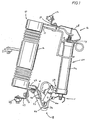
- Cutout mounting 10 generally comprises insulator 12 and upper and lower terminal assemblies 16 and 18, respectively, which are mounted on opposite ends of insulator 12 on upper and lower terminal support members 17 and 34.
- Upper terminal assembly 16 generally includes terminal pad 42, for receiving and clamping an electrical line conductor (not shown), conducting strap 28 and a cup contact 26 which is integrally formed in conducting strap 28.
- Conducting strap 28 electrically interconnects cup contact 26 and terminal pad 42 through terminal shunt 29.
- Lower terminal assembly 18 generally includes terminal pad 44, current shunt 47 and mounting hinge 35. Hinge 35 includes a pair of hanger arms 36 and is formed of brass or another electrically conducting material.
- U-shaped elbows 40 for supporting fuseholder 50. Attached to upper surface 41 of mounting hinge 35 are conducting spring clips 45 biased against the hinge assembly of the fuseholder 50 to insure good electrical contact. Terminal pad 44 is provided for receiving and clamping an electrical line conductor (not shown). Lower current shunt 47 provides good electrical contact between mounting hinge 35 and lower terminal pad 44.
- fuseholder 50 comprises a full range, current limiting dropout fuseholder, similar to that described and claimed in co-pending U.S. patent application, Serial No. 07/946,961, filed September 17, 1992, the entire disclosure of which is incorporated herein by reference. That application discloses a new and unique current limiting fuse and dropout fuseholder which possesses many significant advantages over prior art fuses and fuseholders, such as, for example, by providing a full range of current interruption without the hazards and nuisances associated with prior-art expulsion fuses. Further, the fuse and fuseholder of Serial No. 07/946,961 may be made much smaller and more compact than even prior art current limiting fuses, enabling the fuseholder to be employed in locations having relatively small mounting spaces or clearances.
- Fuseholder 50 of the present invention is intended for generally lower current-rated fuseholder applications, such as those rated 12 amps and below, and generally comprises fuse body 52 having upper cap assembly 54 and lower cap and hinge assembly 58.
- Upper cap assembly 54 includes a top contact 56.
- Lower cap and hinge assembly 58 includes a conducting hinge member 60 which, as described below, is interconnected such that there exists a continuous current path through fuse body 52 between hinge member 60 and top contact 56.
- Top contact 56 is disposed within the recess of cup contact 26, and hinge member 60 is engaged by hanger arms 36 of cutout mounting 10.
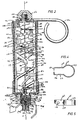
- fuse body 52 includes an insulative cartridge or fuse tube 70 disposed about longitudinal fuse axis 51.
- a high current fusible element 78 and a low current fusible element 80 are housed in fuse tube 70 and are connected in series between upper and lower element terminations 84, 86 respectively.
- Fuse tube 70 is a generally tubular member which is closed at its ends by upper and lower closures 72, 74, respectively.
- Fuse body 52 houses an insulative supporting structure known as a spider 76 which supports fusible elements 78 and 80.
- High purity silica sand 82 or other materials having suitable interrupting and insulation characteristics surrounds spider 76 and fusible elements 78, 80 and fills the unused volume within fuse body 52.
- Spider 76 is made of an inorganic mica and it includes four arms 100 radiating from the longitudinal axis 51, three of arms 100 being visible in Figure 2. Evenly spaced along the length of each arm 100 are element support surfaces 102.
- Upper and lower element terminations 84, 86 respectively are formed of a conducting material, preferably copper, and serve as supports for arms 100 of spider 76 and as landings and termination points for fusible elements 78, 80 and for the upper end of auxiliary wire 120 as described below.
- Element terminations 84, 86 include angular tabs 209 for maintaining the separation between spider arms 100.
- high current fusible element 78 itself comprises a series combination of two elements: a first ribbon element 90 and a series-connected wire element 94.
- Ribbon 90 and wire 94 are interconnected by series connection 96, formed by a copper conducting strap 97 that is supported on spider 76, ribbon 90 and wire 94 each being soldered to strap 76.
- the upper end of ribbon 90 is soldered to conducting tab 156 on upper element termination 84.
- both the ribbon element 90 and wire element 94 are made of silver, although other electrically conducting materials may be employed.
- Silver ribbon 90 has a width within the range of approximately 3,175 to 6,350 mm (0.125 to 0.25 inches), and preferably is 4,775 mm (0.188 inches).
- the thickness of ribbon 90 should be between approximately 0,051 to 0,152 mm (0.002 to 0.006 inches.
- the cross-sectional area of ribbon element 90 is significantly reduced at spaced-apart locations along its length by means of holes that are formed through the ribbon's thickness forming reduced area portions 92. As an alternative to holes, notches may be formed along the edges of ribbon 90, or other means may be used to remove conducting material from the element 90 and thereby reduce the cross-sectional area.
- reduced area portions 92 are positioned between spider arms 100 and are spaced apart from element support surfaces 102 and from the fuse tube 70.
- the center of reduced area portions 92 be at least approximately 4,57 mm (0.18 inches) from element support surfaces 102 of spider arms 100.
- the clearances between the center of reduced area portion 92 and the inside wall 71 of fuse tube 70 be between approximately 4,57 and 6,35 mm (0.18 and 0.25 inches), 5,84 mm (0.23 inches) being the most preferred clearance, as measured along a radius from fuse axis 51.
- the wire element 94 of high current fusible element 78 is selected to have the same I 2 T melting characteristics along its entire length as the I 2 T melting characteristics of the reduced area portions 92 of ribbon element 90.
- a wire element 94 is selected such that the same current that causes reduced area portions 92 of ribbon 90 to melt will also cause the entire length of wire element 94 to melt.
- element 90 and element 94 are both made from material having the same resistivity, such as where they are both made form silver as is preferred, then the I 2 T melting characteristics of reduced area portions 92 and wire element 94 may be matched by selecting a wire element 94 that has a cross-sectional area substantially equal to the cross-sectional area of the ribbon element 90 at the reduced area portions 92.
- the length of wire element 94 is selected so as to be not greater than 50% of the length of the entire high current fusible element 78. It is preferred that the wire element 94 have a length of approximately 30% of the length of the entire high current fusible element 78.
- the series-connected ribbon element 90 and wire element 94 are helically wound on the element support surfaces 102 of the spider arms 100 and connected in series with the low current fusible element 80, which is also helically disposed about the spider arms 100.
- the series connector between wire element 94 and low current fusible element 80 is formed by copper conducting strap 79 which is supported on spider 76.
- Low current fusible element 80 is designed to operate at a predetermined current level below that level at which high current fusible element 78 is designed to operate.
- low current fusible element 80 is comprised of one or more parallel connected conducting wires 110 (one shown in Figure 2), which are preferably formed of silver or other good electrically conductive material and insulated in a silicone rubber covering 114. The covered wire 110 is then helically wrapped about the lower section of spider 76.
- One end of wire 110 is attached to conducting strap 79 at termination point 116 by soldering.
- the other end of wire 110 is conductively attached to tab 211 of lower element termination 86 also by soldering.
- Wire 110 of fusible element 80 is made from two approximately equal lengths of wire that are soldered together as at junction 112 with a solder having a substantially lower melting temperature than that of wire 110.
- the electrically conductive material used for wire 110 or the solder used at junction 112 has thermal characteristics causing it to melt at a temperature consistent with the time-current characteristic requirements of the fuse.
- junction 112 is completely insulated by covering 114, for clarity, wire 110 is depicted in Figure 2 with a portion of covering 114 cut away.
- auxiliary wire 120 is disposed within fuse body 52.
- auxiliary wire 120 is formed of silver for higher current rated fuses and a conductor of higher electrical resistivity such as nichrome for lower current rated fuses.
- Auxiliary wire 120 is wound about spider 76 in notches 106 which are formed in spider arms 100 between element support surfaces 102. Notches 106 are formed in spider arms 100 preferably to a depth 6,35 mm (0.25 inches) below the element support surface 102.
- auxiliary wire 120 is generally concentrically disposed within the helix formed by ribbon 90, and wires 94, 110. In this fashion, auxiliary wire 120 does not contact ribbon 90, or wires 94,110 except, as described below, near its upper point of termination.
- a turn of auxiliary wire 120 closest to interconnection point 96 is disposed so as to be in close proximity to interconnection point 96, forming a spark gap 98 therebetween.
- spark gap 98 as measured between interconnection point 96 and auxiliary wire 120 at their closest point is approximately 0.12 inches.
- auxiliary wire 120 is disposed on spider arm segment 108 of notch 107. Segment 108 is adjacent to the element support surface 102 that is closest to interconnection point 96, and has a reduced depth relative to the remainder of notch 107, thereby raising wire 120 to the proper spacing from ribbon element 90 and wire element 94.
- an insulative extension may be clipped or otherwise fastened to spider arm 100 adjacent to interconnection point 96.
- auxiliary wire 120 is positioned on the extension at the distance away from interconnection 96 necessary to form spark gap 98 having the proper dimension.
- an electrically conductive clip (not shown) may be positioned so as to be in contact with the auxiliary wire 120 at one point and having an opposite end forming a spark gap 98 of the proper dimension to interconnection point 96.
- a lower segment 121 of auxiliary wire 120 is insulated in a silicone rubber covering as it enters the space occupied by the helix formed by wire 110 of low current fusible element 80.
- the upper end of auxiliary wire 120 is soldered to tab 156 on upper element termination 84.
- the lower segment 121 of auxiliary wire 120 terminates on flanged receptacle 186 which is made of brass or other conducting material and retained in a central recess 185 formed along fuse axis 51 in the lower end of spider 76.
- a conducting insert 188 is inserted into receptacle 186 and is electrically connected to a trigger wire 204 which preferably is made of high strength and high electrical resistance nichrome.
- Trigger wire 204 extends outside of fuse body 52 through lower closure 74.
- Conducting receptacle 186, insert 188 and trigger wire 204 are all electrically insulated from lower closure 74.
- upper cap assembly 54 generally comprises top contact 56, pull ring 132, top end cap 138 and upper element termination 84, all of which are attached and their positions relative to one another maintained by the use of a single fastener, stud 134.
- An o-ring seal 136 is disposed about stud 134 between top contact 56 and end cap 138.
- Stud 134 includes a central longitudinal bore (not shown) to permit filling of fuse tube 70 with sand 82 upon assembly of fuseholder 50.
- Lower closure 74 generally comprises bottom end cap 180, lower element termination 86, seal member 182, positioner 184, conductive washer 176 and insulative spacer 174.
- Bottom end cap 180 is formed of copper alloy or other conducting material and generally includes a cylindrical body portion 190 disposed about fuse tube 70, and a generally cylindrical reduced diameter extension 194 attached to and extending from the center of cylindrical body portion 190 thereby forming an interior recess within extension 194.
- Extension 194 and body 190 are generally coaxially aligned with fuse axis 51.
- An aperture 196 is formed substantially in the center of lower surface 195 of extension 194 at the intersection with axis 51.
- Lower element termination 86 includes central aperture 214 which is substantially aligned with fuse axis 51, and further includes conducting tab 211 which serves as a landing and termination point for wire 110 of low current fusible element 80 as shown in Figure 2.
- Lower element termination 86 is electrically connected to bottom end cap 180 by means of conducting tab 192.
- Tab 192 is formed on and extends from element termination 86 through hole 193 formed in bottom end cap 180. The portion of tab 192 extending through end cap 180 is bent over and soldered to cap 180.
- insulative spacer 174 Coaxially disposed within the central recess of end cap extension 194 are insulative spacer 174, conductive washer 176, wire positioner 184 and seal member 182.
- Seal member 182 comprises a rubber washer having central aperture 200.
- Wire positioner 184 comprises an insulative washer made of mica or nylon or other insulating material and includes central aperture 202.
- Washer 176 is preferably made of an electrically conducting material and includes a central aperture 178 and an outer edge surface 177 which engages the walls of extension 194 so as to create a current path therethrough.
- Insulative spacer 174 which may be made of rubber or nylon, for example, includes a central aperture 175.
- Trigger wire 204 is brazed or soldered to conducting insert 188 which preferably is formed of brass.
- Insert 188 includes flange 189 which is disposed between seal member 182 and positioner 184.
- Aperture 202 of wire positioner 184 has a diameter that is smaller than the diameter of aperture 178 of conducting washer 176 so as to centrally position trigger wire 204 in aperture 178.
- Receptacle 186 adapted to receive and electrically engage insert 188, is disposed through central hole 214 in lower element termination 86 and is retained in central recess 185 in the lower end of spider 76.
- Receptacle 186 is attached to, and in conducting engagement with, auxiliary wire 120 as previously described, but does not contact element termination 86.
- Conducting insert 188 is inserted into conducting receptacle 186 through hole 214 of lower element termination 86 during assembly of fuse body 52 with trigger wire 204 extending out of fuse body 52 through aperture 196 in end cap 180, passing through apertures 175, 178, 202, 200 of spacer 174, conducting washer 176, positioner 184, and seal 182, respectively.
- auxiliary wire 120 The lower segment 121 of auxiliary wire 120, receptacle 186, insert 188 and trigger wire 204 are all electrically insulated from lower cap and hinge assembly 58.
- a spark gap 210 which preferably is approximately 0.040 inches for all voltage and current ratings for fuseholder 50, is thus formed between trigger wire 204 and washer 176.
- Lower cap and hinge assembly 58 of fuseholder 50 generally includes hinge member 60, latch 62, latch plate 66, spring 63, current interchange 68, sleeve 69 and connective member 64.
- connective member 64 functions like a clamp and generally includes a strap portion 215 and a pair of hinge supporting members 217 attached thereto. The ends 216 of hinge supporting members 217 are bent toward one another and formed at substantially right angles to hinge supports 217. Two pairs of aligned holes 218, 220 are formed in hinge supporting members 217. As best shown in Figure 3, fastener 225 is disposed through aligned holes 220 in order to draw together hinge supporting members 217 and to secure and clamp strap portion 215 of connective member 64 about bottom end cap 180.
- hinge member 60 generally comprises base portion 232 and a pair of outwardly extending side members 234.
- Side members 234 include tapered edge 240, shoulder 244 and two pairs of aligned holes 236, 250.
- Holes 236 are formed through side members 234 adjacent tapered edge 240.
- Shoulder portions 244 have trunions 246 extending outwardly therefrom and include cam-like electrical contact surfaces 248 adapted for electrical engagement with conducting spring clips 45 of mounting hinge 35 shown in Figures 1 and 3.
- Holes 250 are formed in side members 234 between holes 236 and shoulders 244.
- Base 232 extends between side members 234 and includes slot 254.
- Slot 254 generally bisects base 232 forming a pair of leg portions 256.
- Legs 256 include ends 258 which extend outwardly from base 232 at an angle which is substantially equal to 45° and form a shoulder which engages and supports one end of the current interchange 68, best shown in Figure 3.
- sleeve 69 generally comprises a cylindrical body 222 having reduced diameter portions 224 at each end, forming shoulders 228.
- a central bore 226 is longitudinally formed through sleeve 69.
- Reduced diameter portions 224 are disposed in holes 218 of hinge supporting members 217 of connective member 64 ( Figure 4) such that members 217 abut shoulders 228.
- Sleeve 69 provides a spacing means to maintain the proper separation between hinge supporting members 217 and provides a bearing means for a pin 230, which is disposed through central bore 226 and which supports hinge member 60 ( Figure 3).
- latch 62 generally comprises base 260, side members 262, and fuse restraining end 268.
- Side members 262 are attached to, and extend substantially perpendicularly from, base 260.
- Side members 262 include ears 264 having aligned holes 266 formed therein.
- Pin 252 ( Figure 3) is disposed through aligned holes 266 such that latch 62 is rotatably mounted about pin 252.
- Spring 63 is also mounted around pin 252 between side members 262 to bias latch 62 to rotate about pin 252 in a clockwise direction as viewed in Figure 3.
- Base 260 of latch 62 includes latching surface 267 extending between sides 262 for engaging latch plate 66 as described in more detail below.
- a notch 269 is formed in latching surface 267 for receiving spring arm 65 of spring 63, best shown in Figure 3.
- the free end of latch 62 comprises fuse retaining end 268 which includes elongate aperture 272.
- Latch member 62 is preferably made of stainless steel, although any conductive or insulative material having sufficient rigidity and strength may be employed.
- latch 62 is retained in a latched or supporting position beneath end cap 180 by trigger wire 204 and bobbin 124.
- Bobbin 124 is made of nylon or other insulative material and generally comprises a spool-shaped body 126 and an annular extension 128 attached to body 126. A central aperture 129 is formed through body 126 and extension 128.
- Annular extension 128 of bobbin 124 is disposed through aperture 272 in latch 62 and the end of trigger wire 204 extending from fuseholder 52 is disposed through central bore 129 of bobbin 124.
- Trigger wire 204 is then bent and pressed into a radially formed groove 127 in lower surface of spool body 126 and held in place against the sides of body 126 by clamping band 130.
- latch surface 267 of latch 62 engages latching surface 276 of latch plate 66 to retain hinge member 60 and connective member 64 in fixed angular relationship to one another in a "contracted” and “charged” position, and prevent rotation about the joint means, i.e., pin 230 and sleeve 69.
- latch plate 66 is a generally flat metal plate having a projecting latch surface 276 for engaging latching surface 267 of latch 62 (Figure 10).
- Latch plate 66 further includes a notch 278 for receiving fastener 225 of connective member 64, a key way 280 for use in installing and removing fuseholder 50 by "hot stick," and an aperture 284 for receiving pin 290 shown in Figure 3.
- Latch plate 66 further includes aperture 282 for receiving body 222 of sleeve 69 which, as previously described, is disposed between hinge supporting members 217 of connective member 64.
- Pin 230 is disposed through central bore 226 of sleeve 69 and through holes 236 of hinge member 60.
- Latch plate 66 is received in slot 254 of hinge member 60 ( Figure 6) and includes a stop shoulder 227 for limiting its rotation on pin 230 through engagement with pin 252.
- This connection means causes latch plate 66 and connective member 64 to always rotate as a single unit along with fuse body 52 about the joint means, i.e. pin 230 and sleeve 69.
- Current interchange 68 is best shown in Figures 3 and 12. As shown, pin 290 is disposed through aperture 284 of latch plate 66 and provides support for current interchange 68.
- Current interchange 68 is preferably formed of phosphor bronze, a good electrical conducting material that is also suitable for use as a spring.
- Current interchange 68 includes a pair of U-shaped legs 292, 293 separated by slot 294 and connected by segment 296.
- Current interchange 68 comprises a means for conducting current between bottom end cap 180 of fuse body 52 and hinge member 60. Legs 292, 293 straddle latch plate 66, and are supported on pin 290 which projects from latch plate 66.
- Connecting segment 296 electrically engages bottom end cap 180 while ends 298 of legs 292, 293 electrically engage the ends 258 of legs 256 of hinge member 60.
- current interchange 68 acts as a spring and imparts approximately 12 inch-pounds of torque between hinge 60 and fuse body 52 which assists hinge member 60 to rotate to its extended position to allow fuseholder 50 to drop out of engagement with cutout mounting 10.
- Fuseholder 50 is shown in Figures 1 and 3 with hinge member 60 and connective member 64 in their contracted and charged position, and with latch 62 and latch plate 66 latched. So latched, fuseholder 50 is in its extended position and current is conducted from upper terminal 16 of cutout mounting 10 through fuseholder 50 to lower terminal assembly 18 by means of bottom end cap 180, current interchange 68, hinge member 60 and conducting spring clips 45 to mounting hinge 35 of lower terminal assembly 18.
- the first path comprises the series connected high current and low current fusible elements 78, 80.
- the second current path is electrically in parallel with the first current path and comprises auxiliary conductor 120, trigger wire 204, spark gap 210 and conducting washer 176.
- the third current path is formed by ribbon element 90, spark gap 98, the lower portion of auxiliary wire 120, spark gap 210 and conducting washer 176.
- melting of the high current element 78 begins at the reduced area portions 92 of ribbon element 90 and, simultaneously, along the entire length of the wire element 94, the wire element 94 having substantially the same I 2 T melting characteristics as the ribbon element 90 at the reduced area portions 92.
- An electrical arc develops at each of the melted sections. These arcs give off tremendous heat which melts or fuses the sand surrounding those portions of the element experiencing the arc into glass-like tunnel structures called fulgurites.
- fulgurites develop along the entire length of wire element 94 and in short sections at each reduced area portion 92 of ribbon element 90, the impedance of the current path formed by elements 78 and 80 increases, and the voltage across this impedance also increases accordingly.
- edge 177 of conducting washer 176 is electrically connected to one end of the series combination of elements 78, 80 (the first current path) through lower end cap 180, and because trigger wire 204 is electrically connected to the other end of the series combination of elements 78, 80 through auxiliary wire 120, conducting receptacle 186 and insert 188 (the second current path), the voltage across the series combination of elements 78, 80 appears directly across spark gap 210.
- gap 210 will break down and begin to conduct, and the fault current is shifted from the increased electrical resistance of the first current path to the second current path having a low electrical resistance.
- auxiliary wire 120 The high current now being conducted through the second current path quickly causes auxiliary wire 120 to begin to melt.
- the resistance in the second current path created as the fulgurite develops in the path of wire 120 gives rise to a voltage across elements 78, 80 of the first current path.
- the short fulgurite sections created in ribbon element 90 will reach their breakdown voltage level.
- the dielectric strength at the long fulgurite section formed about wire element 94 exceeds the voltage that can develop across adjacent sections of auxiliary wire 120. Therefore, gap 98 will breakdown, and in conjunction with the short fulgurite sections in ribbon element 90, will form the final or third current path through fuseholder 50.
- Trigger wire 204 has a high resistance.
- the high I 2 R heating through trigger wire 204 coupled with the heat generated by the arc across gap 210 will sever trigger wire 204, thereby acting as a release means for releasing and freeing latch 62 from retainment by trigger wire 204 and bobbin 124.
- fuse restraining end 268 of latch 62 no longer held in contact with bottom end cap 180, is biased away from end cap 180 by spring 63.
- dropout of fuseholder 50 is dependent upon the shifting of the fault current from fusible elements 78, 80 into auxiliary wire 120 such that trigger wire 204 is severed by the heat generated from the arc that is formed as current is conducted across spark gap 210.
- auxiliary wire 120 it is important from the standpoint of causing fuseholder 50 to drop open that auxiliary wire 120 not melt too quickly, but instead remain conductive long enough for the arcing across gap 210 to sever trigger wire 204.
- auxiliary wire 120 The melting time of auxiliary wire 120 is dependant upon the magnitude of the current conducted through the wire, the size of the wire, and the material from which the wire is made. Each wire, then, has a different characteristic melting curve. Given two wires of the same material, one wire being larger than the other, the larger wire will not melt as quickly as the smaller wire for any fault current of a magnitude large enough to melt the wires. For a more specific example, a 0,16 mm (0.0063 inch) diameter NiCr wire will melt at approximately 0.035 seconds when experiencing a 6 amp current. By contrast, a larger 0,20 mm (0.008 inch) diameter NiCr wire will require approximately 0.3 seconds to melt when carrying the same current. Thus, by choosing a larger diameter wire as auxiliary wire 120, the arcing across gap 210 can be sustained for a longer period so as to ensure that trigger wire 204 is severed.
- the dropout function is of secondary importance to the ability of fuseholder 50 to interrupt the flow of fault current and to do so before the dropout action of fuseholder 50 causes any significant separation between the upper contact assembly 54 of fuseholder 50 and the cup contact 26 of cutout mounting 10.
- the level of current that the fuse must be capable of interrupting and the allowable let through current (let through I 2 T) during interruptions under a at all fault current levels decreases accordingly.
- the size of auxiliary wires 120 used in higher current rated fuses can be relatively large without having any adverse affect on such fuses' interrupting performance.
- the size of the auxiliary wires 120 normally used in high current-rated fuses can approach the size of the high current fusible element 78 used in lower current-rated fuses and, if used in such lower current-rated fuses, can adversely affect the interrupting performance by causing excessive let through I 2 T for these lower current-rated fuseholders 50.
- the trigger wire 204 will be severed within several 60 Hz cycles after the current is shifted to the second current path which includes auxiliary wire 120. In these cases, the auxiliary wire 120 must be small enough that it can melt and interrupt these lower level currents within the next several cycles of 60 Hz current flow.
- auxiliary wire 120 can be conflicting. On one hand, the wire must be large enough to allow completion of the severing of the trigger wire 204, while on the other hand the wire 120 must be small enough that it does not impede successful fault current interruption by the fuse. Difficulties in satisfying both requirements increase with lower current-rated fuses since mechanical requirements for the trigger wire 204 do not allow the size of trigger wire 204 to be reduced accordingly.
- wire element 94 in high current element 78 in conjunction with spark gap 98 adjacent to the interconnection of fusible elements 90 and 94 ensures that conduction occurs across gap 210 for a period of time long enough to sever trigger wire 204, when interrupting any level of fault current.
Landscapes
- Fuses (AREA)
Claims (7)
- Sicherungsbaugruppe, die einen Sicherungskörper (52); einen ersten (138) und einen zweiten (180) leitenden Anschluß an dem Körper, einen ersten Stromweg (78, 80) zwischen den Anschlüssen, der ein erstes Schmelzelement (90) in Reihe mit einem zweiten Schmelzelement (94) umfaßt, wobei das erste Schmelzelement voneinander beabstandete Abschnitte (92) enthält, die eine verringerte Querschnittsfläche aufweisen, und das zweite Schmelzelement die gleichen 12T-Schmelzeigenschaften hat, wie die verringerte Querschnittsfläche des ersten Schmelzelementes; und einen zweiten Stromweg (120, 204, 210) zwischen den Anschlüssen elektrisch parallel zu dem ersten Stromweg umfaßt, wobei der zweite Stromweg einen Leiter in Reihe mit einer ersten Funkenstrecke (210) umfaßt,
dadurch gekennzeichnet, daß der zweite Stromweg umfaßt: einen auslösenden Leiter (204), der sich außerhalb des Sicherungskörpers erstreckt und mit einer gespannten Trageklinke (60) verbunden ist, die zwischen einer tragenden und einer nichttragenden Position unter dem Sicherungskörper bewegt werden kann, so daß, wenn der Strom über die erste Funkenstrecke fließt, der auslösende Leiter (204) durchtrennt wird und so die Klinke (62) freigibt und Herausfallen der Sicherungsbaugruppe ermöglicht. - Sicherungsbaugruppe nach Anspruch 1, wobei das zweite Schmelzelement (94) eine Länge hat, die nicht mehr als 50% der Gesamtlänge des ersten (90) und des zweiten (94) Schmelzelementes, die in Reihe miteinander verbunden sind, beträgt.
- Sicherungsbaugruppe nach Anspruch 1 oder 2, wobei das erste (90) und das zweite (94) Schmelzelement, die in Reihe miteinander verbunden sind, ein Hochstrom-Schmelzelement (78) umfassen, und wobei der erste Stromweg ein Schwachstrom-Schmelzelement (80) in Reihe mit dem Hochstrom-Element umfaßt.
- Sicherungsbaugruppe nach einem der vorangehenden Ansprüche, wobei das erste Schmelzelement (90) und das zweite Schmelzelement (94) an einer Verbindungsstelle (96) miteinander verbunden sind, und wobei eine zweite Funkenstrecke (98) zwischen der Verbindungsstelle und dem Leiter des zweiten Stromweges ausgebildet ist.
- Sicherungsbaugruppe nach Anspruch 4, wobei die zweite Funkenstrecke (98) ungefähr 3 mm (0,12 Inch) mißt.
- Sicherungsbaugruppe nach Anspruch 4 oder 5, wobei der zweite Stromweg einen Hilfsleiter (120) in Reihe mit der ersten Funkenstrecke (210) umfaßt.
- Sicherungsbaugruppe nach einem der vorangehenden Ansprüche, wobei das zweite Schmelzelement einen Draht (94) umfaßt, dessen Querschnittsfläche im wesentlichen der der verringerten Querschnittsfläche des ersten Schmelzelementes (90) entspricht.
Applications Claiming Priority (2)
| Application Number | Priority Date | Filing Date | Title |
|---|---|---|---|
| US174594 | 1993-12-27 | ||
| US08/174,594 US5463366A (en) | 1992-09-17 | 1993-12-27 | Current limiting fuse and dropout fuseholder |
Publications (3)
| Publication Number | Publication Date |
|---|---|
| EP0660351A2 EP0660351A2 (de) | 1995-06-28 |
| EP0660351A3 EP0660351A3 (de) | 1996-04-24 |
| EP0660351B1 true EP0660351B1 (de) | 1999-05-26 |
Family
ID=22636745
Family Applications (1)
| Application Number | Title | Priority Date | Filing Date |
|---|---|---|---|
| EP94309367A Expired - Lifetime EP0660351B1 (de) | 1993-12-27 | 1994-12-14 | Verbesserte strombegrenzende Schmelzsicherung und dropout Sicherungshalter |
Country Status (13)
| Country | Link |
|---|---|
| US (2) | US5463366A (de) |
| EP (1) | EP0660351B1 (de) |
| JP (1) | JPH07254348A (de) |
| KR (1) | KR100370818B1 (de) |
| CN (1) | CN1038623C (de) |
| AT (1) | ATE180595T1 (de) |
| AU (1) | AU679288B2 (de) |
| BR (1) | BR9405274A (de) |
| CA (1) | CA2139023A1 (de) |
| DE (1) | DE69418688D1 (de) |
| TN (1) | TNSN94143A1 (de) |
| TW (1) | TW305079B (de) |
| ZA (1) | ZA9410195B (de) |
Families Citing this family (27)
| Publication number | Priority date | Publication date | Assignee | Title |
|---|---|---|---|---|
| US5986534A (en) * | 1993-07-12 | 1999-11-16 | The University Of Sydney | Dropout fuse having electrical energy absorbing device |
| DE19702780C1 (de) * | 1996-02-29 | 1998-02-05 | Driescher Spezialfab Fritz | Hochspannungs-Hochleistungs-Sicherung |
| JP3017950B2 (ja) * | 1996-09-09 | 2000-03-13 | 東洋システム株式会社 | 電流・温度複合ヒューズ |
| US5854582A (en) * | 1997-08-27 | 1998-12-29 | Hubbell Incorporated | Pivotal latching mechanism with interengageable latch arm and catch in a sectionalizer assembly |
| DE19757026A1 (de) * | 1997-12-20 | 1999-07-01 | Leonische Drahtwerke Ag | Elektrische Sicherung |
| US6477025B1 (en) * | 1999-10-12 | 2002-11-05 | Innovative Technology, Inc. | Surge protection device with thermal protection, current limiting, and failure indication |
| US6392526B1 (en) * | 2000-04-28 | 2002-05-21 | Hubbell Incorporated | Fuse cutout with mechanical assist |
| US6462639B1 (en) * | 2000-07-14 | 2002-10-08 | Hubbell Incorporated | Fuse cutout with dome top contact and knurled fuseholder cap |
| CA2380146C (en) * | 2002-03-02 | 2011-01-04 | S&C Electric Company | High voltage fuse |
| AU2003228645A1 (en) * | 2002-04-26 | 2003-11-10 | S And C Electric Company | Fuse cutout with improved dropout performance |
| CN1298004C (zh) * | 2004-03-26 | 2007-01-31 | 西安交通大学 | 大容量短路电流开断器 |
| US7378933B2 (en) * | 2005-03-24 | 2008-05-27 | Jonathan Paige Rogers | Dual fuse holder |
| US7349189B2 (en) * | 2005-05-06 | 2008-03-25 | Finisar Corporation | Electrical surge protection using in-package gas discharge system |
| NL1030315C2 (nl) * | 2005-10-31 | 2007-05-03 | Craneo Holding B V | Inrichting voor het voeden van apparatuur met uiteenlopende eisen aan de voeding. |
| US20070285867A1 (en) * | 2006-06-13 | 2007-12-13 | Cooper Technologies Company | High resistance current limiting fuse, methods, and systems |
| US20080122571A1 (en) * | 2006-11-28 | 2008-05-29 | Emerson Electric Co. | Fulgurite reducing fuse |
| KR100715627B1 (ko) * | 2007-02-26 | 2007-05-08 | 대원계전주식회사 | 배전용 고압 부싱형 퓨즈홀더와 이를 이용한 배전 구조 |
| KR200452893Y1 (ko) | 2008-12-31 | 2011-03-31 | 엘에스산전 주식회사 | 퓨즈 체킹장치 |
| KR101061236B1 (ko) | 2009-12-29 | 2011-09-01 | 한국전력공사 | 컷 아웃 스위치 |
| FR2960695B1 (fr) * | 2010-05-25 | 2012-06-29 | Areva T & D Canada Inc | Dispositif coupe-circuit a fil fusible muni d'un porte-fusible et d'un casse-fusible a securite de man?uvre et de fonctionnement ameliorees |
| US9115885B2 (en) | 2012-04-12 | 2015-08-25 | Amerlux Inc. | Water tight LED assembly with connector through lens |
| KR101452890B1 (ko) * | 2013-12-04 | 2014-10-22 | 현대중공업 주식회사 | 퓨즈 홀더 |
| CN103811239B (zh) * | 2014-03-13 | 2016-03-02 | 国家电网公司 | 跌落式熔断器 |
| CN105304422B (zh) * | 2015-11-17 | 2018-06-29 | 国家电网公司 | 一种配网线路跌落式开关 |
| US20180233895A1 (en) * | 2017-02-16 | 2018-08-16 | Electrical Materials Company | Localized application of high impedance fault isolation in multi-tap electrical power distribution system |
| CN114264983B (zh) * | 2021-12-24 | 2023-09-19 | 上海乾行达航天科技有限公司 | 一种高低温环境模拟试验箱 |
| DE102022002431A1 (de) | 2022-07-05 | 2024-01-11 | Siba Fuses Gmbh | Verwendung einer HH-Sicherung für ein Drop-Out-Sicherungssystem |
Family Cites Families (31)
| Publication number | Priority date | Publication date | Assignee | Title |
|---|---|---|---|---|
| DE656796C (de) * | 1936-02-23 | 1938-02-18 | Voigt & Haeffner Akt Ges | Schmelzleiteranordnung fuer Sicherungen, insbesondere fuer Hochspannungssicherungen |
| US2260084A (en) * | 1940-04-04 | 1941-10-21 | Matthews W N Corp | Electrical cutout |
| US3437971A (en) * | 1967-06-26 | 1969-04-08 | Mc Graw Edison Co | Current limiting fuse |
| US3755769A (en) * | 1969-10-31 | 1973-08-28 | Mc Graw Edison Co | Modularized fuse with precise gap |
| US3611240A (en) * | 1970-05-04 | 1971-10-05 | Mc Graw Edison Co | Dropout fuse |
| US3680019A (en) * | 1970-06-08 | 1972-07-25 | Chase Shawmut Co | High-voltage fuse having a plurality of fuse links wound helically around an insulating mandrel |
| US3671909A (en) * | 1971-02-17 | 1972-06-20 | Chase Shawmut Co | High-voltage fuse with one piece fuse links |
| US3827010A (en) * | 1972-03-06 | 1974-07-30 | Westinghouse Electric Corp | Composite sectionalized open-type drop-out-type fusible output with series enclosed current limiting fuse |
| US3774137A (en) * | 1972-09-22 | 1973-11-20 | Westinghouse Electric Corp | Latch and guide assembly for a dropout electrical fuse |
| US3863187A (en) * | 1973-06-04 | 1975-01-28 | Chance Co Ab | Total range fault interrupter |
| US3813627A (en) * | 1973-06-11 | 1974-05-28 | Gen Electric | Current limiting fuse having improved low current interrupting capability |
| US3825871A (en) * | 1973-11-20 | 1974-07-23 | Westinghouse Electric Corp | Electric fuse with trip device |
| US3913050A (en) * | 1974-06-03 | 1975-10-14 | Rte Corp | Fuse assembly for current limiting fuses |
| US4114128A (en) * | 1974-10-30 | 1978-09-12 | Westinghouse Electric Corp. | Composite sectionalized protective indicating-type fuse |
| US4028655A (en) * | 1975-10-09 | 1977-06-07 | General Electric Company | Electrical current limiting fuse with bound sand filler and improved low current fault clearing |
| US4011537A (en) * | 1975-11-19 | 1977-03-08 | S & C Electric Company | Composite dropout fuse device |
| US4001749A (en) * | 1975-12-17 | 1977-01-04 | The Chase-Shawmut Company | Electric fuse for elevated circuit voltages |
| US4134094A (en) * | 1977-05-05 | 1979-01-09 | Mcgraw-Edison Company | Fuse element |
| US4123738A (en) * | 1977-05-16 | 1978-10-31 | Mcgraw-Edison Company | High voltage current limiting fuse |
| US4158830A (en) * | 1977-09-27 | 1979-06-19 | S & C Electric Company | Fitting for a circuit-interrupting device |
| US4184138A (en) * | 1977-11-25 | 1980-01-15 | A. B. Chance Company | Offset, series connected current limiting fuse and expulsion fuseholder assembly for opengate cutout |
| US4414527A (en) * | 1980-03-24 | 1983-11-08 | S&C Electric Company | Contact assembly for a fuse cutout |
| US4336521A (en) * | 1981-03-11 | 1982-06-22 | Kozacka Frederick J | Electric fuse |
| US4388603A (en) * | 1981-05-15 | 1983-06-14 | Mcgraw-Edison Company | Current limiting fuse |
| US4481495A (en) * | 1982-10-29 | 1984-11-06 | S&C Electric Company | Fusible element for a current-limiting fuse having groups of spaced holes or notches therein |
| JPS59173249U (ja) * | 1983-05-07 | 1984-11-19 | 日本碍子株式会社 | 避雷器素子を内蔵したオ−プンヒユ−ズカツトアウト |
| JPS59173963U (ja) * | 1983-05-10 | 1984-11-20 | 日本碍子株式会社 | 避雷器素子を内蔵したオ−プンヒユ−ズカツトアウト |
| US4506249A (en) * | 1983-09-08 | 1985-03-19 | Rte Corporation | Fuse element termination for current-limiting fuse |
| US4570146A (en) * | 1984-06-21 | 1986-02-11 | Huber William J | High voltage fuse |
| US4625196A (en) * | 1985-06-24 | 1986-11-25 | Rte Corporation | Modular under oil expulsion fuse cartridge assembly |
| US5274349A (en) * | 1992-09-17 | 1993-12-28 | Cooper Power Systems, Inc. | Current limiting fuse and dropout fuseholder for interchangeable cutout mounting |
-
1993
- 1993-12-27 US US08/174,594 patent/US5463366A/en not_active Expired - Lifetime
-
1994
- 1994-12-14 EP EP94309367A patent/EP0660351B1/de not_active Expired - Lifetime
- 1994-12-14 AT AT94309367T patent/ATE180595T1/de not_active IP Right Cessation
- 1994-12-14 DE DE69418688T patent/DE69418688D1/de not_active Expired - Lifetime
- 1994-12-20 TW TW083111948A patent/TW305079B/zh not_active IP Right Cessation
- 1994-12-21 AU AU81627/94A patent/AU679288B2/en not_active Ceased
- 1994-12-21 ZA ZA9410195A patent/ZA9410195B/xx unknown
- 1994-12-23 CA CA002139023A patent/CA2139023A1/en not_active Abandoned
- 1994-12-27 CN CN94120733A patent/CN1038623C/zh not_active Expired - Fee Related
- 1994-12-27 JP JP6325038A patent/JPH07254348A/ja active Pending
- 1994-12-27 BR BR9405274A patent/BR9405274A/pt not_active IP Right Cessation
- 1994-12-27 KR KR1019940037323A patent/KR100370818B1/ko not_active IP Right Cessation
- 1994-12-27 TN TNTNSN94143A patent/TNSN94143A1/fr unknown
-
1995
- 1995-06-07 US US08/484,653 patent/US5760673A/en not_active Expired - Lifetime
Also Published As
| Publication number | Publication date |
|---|---|
| EP0660351A3 (de) | 1996-04-24 |
| CN1110001A (zh) | 1995-10-11 |
| ZA9410195B (en) | 1995-08-25 |
| TW305079B (de) | 1997-05-11 |
| CN1038623C (zh) | 1998-06-03 |
| US5463366A (en) | 1995-10-31 |
| KR950020849A (ko) | 1995-07-26 |
| ATE180595T1 (de) | 1999-06-15 |
| US5760673A (en) | 1998-06-02 |
| DE69418688D1 (de) | 1999-07-01 |
| KR100370818B1 (ko) | 2003-03-29 |
| TNSN94143A1 (fr) | 1995-09-21 |
| CA2139023A1 (en) | 1995-06-28 |
| EP0660351A2 (de) | 1995-06-28 |
| JPH07254348A (ja) | 1995-10-03 |
| AU679288B2 (en) | 1997-06-26 |
| AU8162794A (en) | 1995-07-06 |
| BR9405274A (pt) | 1995-08-01 |
Similar Documents
| Publication | Publication Date | Title |
|---|---|---|
| EP0660351B1 (de) | Verbesserte strombegrenzende Schmelzsicherung und dropout Sicherungshalter | |
| US5355111A (en) | Nested contact and cap assembly for fuseholder | |
| US7724122B2 (en) | Fuse providing circuit isolation and visual interruption indication | |
| EP0121881B1 (de) | Hochspannungssicherung | |
| US5583729A (en) | Terminal bushing having integral overvoltage and overcurrent protection | |
| RU2407122C1 (ru) | Вставной разрядник защиты от перенапряжения | |
| JPS59169029A (ja) | 高温技術電流遮断器 | |
| US4638283A (en) | Exothermically assisted electric fuse | |
| US5485136A (en) | Load break disconnecting device with solid arc suppression means | |
| US5805046A (en) | Current responsive latching apparatus for disconnecting and isolating an electrical device | |
| US5566423A (en) | Delay mechanism for retarding relative movement between two members | |
| US4008452A (en) | Current limiting fuse device for relatively high current | |
| US2572901A (en) | Fuse link | |
| JP2003507852A (ja) | 非ベント型のカットアウト搭載用ヒューズ | |
| CA1251500A (en) | Current limiting fuse with less inverse time-current characteristic | |
| US5936506A (en) | Delay mechanism for retarding relative movement between two members | |
| US3733572A (en) | Current limiting fuse | |
| US2639346A (en) | Transformer protective apparatus | |
| CA1198134A (en) | Device for terminating a fusible element of an interrupting module | |
| US20240013997A1 (en) | Use of a hv hrc fuse for a drop-out fuse system | |
| CA2579932C (en) | Fuse providing circuit isolation and visual interruption indication | |
| CA1129460A (en) | Pressure-operated high-voltage circuit protecting device with high continuous current rating | |
| KR200376480Y1 (ko) | 고압전류 제한퓨즈 | |
| CA1166671A (en) | Fuse having improved switch | |
| JPH0340891B2 (de) |
Legal Events
| Date | Code | Title | Description |
|---|---|---|---|
| PUAI | Public reference made under article 153(3) epc to a published international application that has entered the european phase |
Free format text: ORIGINAL CODE: 0009012 |
|
| AK | Designated contracting states |
Kind code of ref document: A2 Designated state(s): AT BE CH DE DK ES FR GB GR IE IT LI LU MC NL PT SE |
|
| RAX | Requested extension states of the european patent have changed |
Free format text: LT PAYMENT 950112;SI PAYMENT 950112 |
|
| PUAL | Search report despatched |
Free format text: ORIGINAL CODE: 0009013 |
|
| AK | Designated contracting states |
Kind code of ref document: A3 Designated state(s): AT BE CH DE DK ES FR GB GR IE IT LI LU MC NL PT SE |
|
| AX | Request for extension of the european patent |
Free format text: LT PAYMENT 950112;SI PAYMENT 950112 |
|
| 17P | Request for examination filed |
Effective date: 19961011 |
|
| 17Q | First examination report despatched |
Effective date: 19970627 |
|
| RAP1 | Party data changed (applicant data changed or rights of an application transferred) |
Owner name: COOPER INDUSTRIES, INC. |
|
| GRAG | Despatch of communication of intention to grant |
Free format text: ORIGINAL CODE: EPIDOS AGRA |
|
| GRAG | Despatch of communication of intention to grant |
Free format text: ORIGINAL CODE: EPIDOS AGRA |
|
| GRAH | Despatch of communication of intention to grant a patent |
Free format text: ORIGINAL CODE: EPIDOS IGRA |
|
| GRAH | Despatch of communication of intention to grant a patent |
Free format text: ORIGINAL CODE: EPIDOS IGRA |
|
| GRAA | (expected) grant |
Free format text: ORIGINAL CODE: 0009210 |
|
| AK | Designated contracting states |
Kind code of ref document: B1 Designated state(s): AT BE CH DE DK ES FR GB GR IE IT LI LU MC NL PT SE |
|
| AX | Request for extension of the european patent |
Free format text: LT PAYMENT 19950112;SI PAYMENT 19950112 |
|
| LTIE | Lt: invalidation of european patent or patent extension | ||
| PG25 | Lapsed in a contracting state [announced via postgrant information from national office to epo] |
Ref country code: SE Free format text: THE PATENT HAS BEEN ANNULLED BY A DECISION OF A NATIONAL AUTHORITY Effective date: 19990526 Ref country code: NL Free format text: LAPSE BECAUSE OF FAILURE TO SUBMIT A TRANSLATION OF THE DESCRIPTION OR TO PAY THE FEE WITHIN THE PRESCRIBED TIME-LIMIT Effective date: 19990526 Ref country code: LI Free format text: LAPSE BECAUSE OF FAILURE TO SUBMIT A TRANSLATION OF THE DESCRIPTION OR TO PAY THE FEE WITHIN THE PRESCRIBED TIME-LIMIT Effective date: 19990526 Ref country code: IT Free format text: LAPSE BECAUSE OF FAILURE TO SUBMIT A TRANSLATION OF THE DESCRIPTION OR TO PAY THE FEE WITHIN THE PRE;WARNING: LAPSES OF ITALIAN PATENTS WITH EFFECTIVE DATE BEFORE 2007 MAY HAVE OCCURRED AT ANY TIME BEFORE 2007. THE CORRECT EFFECTIVE DATE MAY BE DIFFERENT FROM THE ONE RECORDED.SCRIBED TIME-LIMIT Effective date: 19990526 Ref country code: GR Free format text: LAPSE BECAUSE OF NON-PAYMENT OF DUE FEES Effective date: 19990526 Ref country code: FR Free format text: LAPSE BECAUSE OF FAILURE TO SUBMIT A TRANSLATION OF THE DESCRIPTION OR TO PAY THE FEE WITHIN THE PRESCRIBED TIME-LIMIT Effective date: 19990526 Ref country code: ES Free format text: THE PATENT HAS BEEN ANNULLED BY A DECISION OF A NATIONAL AUTHORITY Effective date: 19990526 Ref country code: CH Free format text: LAPSE BECAUSE OF FAILURE TO SUBMIT A TRANSLATION OF THE DESCRIPTION OR TO PAY THE FEE WITHIN THE PRESCRIBED TIME-LIMIT Effective date: 19990526 Ref country code: BE Free format text: LAPSE BECAUSE OF FAILURE TO SUBMIT A TRANSLATION OF THE DESCRIPTION OR TO PAY THE FEE WITHIN THE PRESCRIBED TIME-LIMIT Effective date: 19990526 |
|
| REF | Corresponds to: |
Ref document number: 180595 Country of ref document: AT Date of ref document: 19990615 Kind code of ref document: T |
|
| REG | Reference to a national code |
Ref country code: CH Ref legal event code: EP |
|
| REF | Corresponds to: |
Ref document number: 69418688 Country of ref document: DE Date of ref document: 19990701 |
|
| REG | Reference to a national code |
Ref country code: IE Ref legal event code: FG4D |
|
| PG25 | Lapsed in a contracting state [announced via postgrant information from national office to epo] |
Ref country code: PT Free format text: LAPSE BECAUSE OF FAILURE TO SUBMIT A TRANSLATION OF THE DESCRIPTION OR TO PAY THE FEE WITHIN THE PRESCRIBED TIME-LIMIT Effective date: 19990826 Ref country code: DK Free format text: LAPSE BECAUSE OF FAILURE TO SUBMIT A TRANSLATION OF THE DESCRIPTION OR TO PAY THE FEE WITHIN THE PRESCRIBED TIME-LIMIT Effective date: 19990826 |
|
| PG25 | Lapsed in a contracting state [announced via postgrant information from national office to epo] |
Ref country code: DE Free format text: LAPSE BECAUSE OF FAILURE TO SUBMIT A TRANSLATION OF THE DESCRIPTION OR TO PAY THE FEE WITHIN THE PRESCRIBED TIME-LIMIT Effective date: 19990827 |
|
| EN | Fr: translation not filed | ||
| REG | Reference to a national code |
Ref country code: CH Ref legal event code: PL |
|
| PG25 | Lapsed in a contracting state [announced via postgrant information from national office to epo] |
Ref country code: LU Free format text: LAPSE BECAUSE OF NON-PAYMENT OF DUE FEES Effective date: 19991214 Ref country code: IE Free format text: LAPSE BECAUSE OF NON-PAYMENT OF DUE FEES Effective date: 19991214 Ref country code: AT Free format text: LAPSE BECAUSE OF NON-PAYMENT OF DUE FEES Effective date: 19991214 |
|
| PLBE | No opposition filed within time limit |
Free format text: ORIGINAL CODE: 0009261 |
|
| STAA | Information on the status of an ep patent application or granted ep patent |
Free format text: STATUS: NO OPPOSITION FILED WITHIN TIME LIMIT |
|
| 26N | No opposition filed | ||
| PG25 | Lapsed in a contracting state [announced via postgrant information from national office to epo] |
Ref country code: MC Free format text: LAPSE BECAUSE OF NON-PAYMENT OF DUE FEES Effective date: 20000630 |
|
| REG | Reference to a national code |
Ref country code: IE Ref legal event code: MM4A |
|
| REG | Reference to a national code |
Ref country code: GB Ref legal event code: IF02 |
|
| PGFP | Annual fee paid to national office [announced via postgrant information from national office to epo] |
Ref country code: GB Payment date: 20091106 Year of fee payment: 16 |
|
| GBPC | Gb: european patent ceased through non-payment of renewal fee |
Effective date: 20101214 |
|
| PG25 | Lapsed in a contracting state [announced via postgrant information from national office to epo] |
Ref country code: GB Free format text: LAPSE BECAUSE OF NON-PAYMENT OF DUE FEES Effective date: 20101214 |