EP0658697B1 - Entkuppelbarer Freilauf - Google Patents
Entkuppelbarer Freilauf Download PDFInfo
- Publication number
- EP0658697B1 EP0658697B1 EP94410101A EP94410101A EP0658697B1 EP 0658697 B1 EP0658697 B1 EP 0658697B1 EP 94410101 A EP94410101 A EP 94410101A EP 94410101 A EP94410101 A EP 94410101A EP 0658697 B1 EP0658697 B1 EP 0658697B1
- Authority
- EP
- European Patent Office
- Prior art keywords
- free
- freewheel
- axis
- ring
- disengageable
- Prior art date
- Legal status (The legal status is an assumption and is not a legal conclusion. Google has not performed a legal analysis and makes no representation as to the accuracy of the status listed.)
- Expired - Lifetime
Links
Images

Classifications
-
- F—MECHANICAL ENGINEERING; LIGHTING; HEATING; WEAPONS; BLASTING
- F16—ENGINEERING ELEMENTS AND UNITS; GENERAL MEASURES FOR PRODUCING AND MAINTAINING EFFECTIVE FUNCTIONING OF MACHINES OR INSTALLATIONS; THERMAL INSULATION IN GENERAL
- F16D—COUPLINGS FOR TRANSMITTING ROTATION; CLUTCHES; BRAKES
- F16D41/00—Freewheels or freewheel clutches
- F16D41/06—Freewheels or freewheel clutches with intermediate wedging coupling members between an inner and an outer surface
- F16D41/064—Freewheels or freewheel clutches with intermediate wedging coupling members between an inner and an outer surface the intermediate members wedging by rolling and having a circular cross-section, e.g. balls
- F16D41/066—Freewheels or freewheel clutches with intermediate wedging coupling members between an inner and an outer surface the intermediate members wedging by rolling and having a circular cross-section, e.g. balls all members having the same size and only one of the two surfaces being cylindrical
-
- B—PERFORMING OPERATIONS; TRANSPORTING
- B25—HAND TOOLS; PORTABLE POWER-DRIVEN TOOLS; MANIPULATORS
- B25J—MANIPULATORS; CHAMBERS PROVIDED WITH MANIPULATION DEVICES
- B25J19/00—Accessories fitted to manipulators, e.g. for monitoring, for viewing; Safety devices combined with or specially adapted for use in connection with manipulators
- B25J19/0004—Braking devices
Definitions
- the present invention relates to a freewheel, i.e. a two-piece coupling element mechanical allowing these two parts to have a movement relative rotation in one direction.
- the present invention relates more particularly a disengageable freewheel which, depending on the active or inactive state a control signal, allows the two parts to rotate relative to each other in both directions or well in only the direction determined by the freewheel, hereinafter the meaning "free".
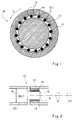
- Figure 1 shows a classic freewheel 8. It includes an internal cylindrical axis 10 surrounded an outer ring 12.
- the interior of the ring 12 comprises a multitude of ramps 13 of the same direction each of which departs from a location close to axis 10 and moves away from this one, clockwise in Figure 1.
- Each time ramp is associated with a roller 14 whose diameter is slightly less than the distance between the circumference from axis 10 of the part furthest from the ramp.
- each ramp ends by a rounded 13-1 matching the associated roller 14.
- this freewheel is the next.
- axis 10 is fixed. If the ring 12 is rotated clockwise, the ramps 13 start rolling on the rollers 14 like a ball bearing. Almost immediately, depending on the set of rollers 14, the diameter of roller 14 becomes less than the space between the circumference of the axis 10 ramps 13; the rollers 14 get stuck and prevent any additional rotation of the ring 12 in the direction schedule.
- the freewheel is locked quickly, so that the rotation performed by the ring 12 clockwise (non-free) is negligible.
- a classic solution for making a wheel free disengageable consists in providing a clutch allowing to couple, for example, axis 10 of the freewheel to a part or to decouple this axis. If the axis is uncoupled, the workpiece can rotate in any direction relative to the ring 12 of the freewheel. If the axis is coupled, the workpiece can only rotate in the direction free.
- Such a clutch system always has a operating clearance between the coupled position and the uncoupled position, which introduces high response and noisy clicks.
- a time of high clutch response (blocking) is dangerous for a surgical robot.
- a robot axis When a robot axis reaches a limit angular position, it must be stopped (by its coupling to a corresponding freewheel). If the response time to mating is high, the limit risk of being crossed before the axis could be stopped.
- stopping the axis is particularly abrupt if you want to respect a certain precision; he is difficult to predict a friction slowdown which would lead to an uncertain dependent stop position of the energy supplied to the axis.
- An object of the present invention is to provide a disengageable freewheel with short response time.
- Another object of the present invention is to provide such a disengageable freewheel which allows in addition to limiting the speed of rotation in the opposite direction to free sense.
- Another object of the present invention is to provide such a disengageable freewheel using which we can get a progressive stop.
- Said freewheel disengageable includes a first and a second part the second of which can only rotate in a free direction predetermined compared to the first. Freewheeling further includes means for driving the first part rotating in the opposite direction to the predetermined direction, from which it follows that the second part can rotate as fast as the first piece in the direction opposite to the predetermined meaning.
- the second piece is a ring and the first a central axis on which the ring can be locked in rotation by a ramp and roller system.
- the first part is driven by a system worm gear.
- the present invention also relates to a joint comprising two freewheels of the aforementioned type, coaxial and opposite free directions.
- the second pieces of each freewheel are integral with a first element of the joint and the drive means are gearmotor groups integral with a second element of the joint.
- a disengageable a freewheel such as that of FIG. 1
- the ring 12 can rotate in the clockwise as fast as axis 10. Indeed, as long as the ring 12 does not rotate as fast as the axis 10, it rotates, relative to the axis 10, in the direction free.
- FIG. 2 represents an embodiment of disengageable freewheel 15 according to the invention.
- the ring 12 a freewheel 8 of the type of FIG. 1 is integral of a part 16.
- the ring 12 can be embedded or else immobilized in rotation and in translation relative to the part 16 by conventional means.
- Axle 10 of the wheel free is integral with the output axis of a geared motor group 18.
- the chassis of group 18 is secured to a Exhibit 20. So, if group 18 is stopped, we are in the situation of a classic freewheel and the part 16 cannot rotate relative to the part 20 that in the free sense, which is represented by a solid arrow S1. (We assume that the axis of group 18 to the stop cannot be driven in rotation by an action external.)
- part 16 can turn by compared to part 20 in its non-free sense at most as fast as axis 10, which is represented by a dashed arrow S2.
- room 16 can always turn in its free direction.
- group 18 plays no only the role of a declutching system but also of speed limiter in the non-free direction of the ring 12.
- Figure 3 shows an application of two freewheels according to the invention with a joint, arms robot for example.
- Two freewheel rings 12 15 and 15 'of the type of Figure 2 are integral with a first segment 22 of the robot arm.
- the two freewheels 15 and 15 ' are coaxial and opposite free directions, indicated by arrows S3 and S4.
- Axles 10 of the wheels free 15 and 15 ' are integral with the output axes of two respective gearmotor groups 18 and 18 '.
- the chassis of groups 18 and 18 ' are integral with the same second segment 24 of the robot arm. Groups 18 and 18 'are of course provided to drive their axes 10 in their respective free senses.
- segment 22 cannot move relative to the segment 24, each direction of movement being blocked by one of the freewheels 15 and 15 '. If one of the groups 18 and 18 'is started, segment 22 cannot move that in the direction of the axis 10 driven in rotation and at more as fast as this one. Freewheel including axis 10 is not driven prevents movement of segment 22 In the opposite way.
- segment 22 can move in any sense, but at most as fast as axis 10 associated with sense of displacement.
- a disengageable freewheel according to the invention used in a system comprising position sensors, such as a robot arm, provides a blockage to the both progressive and precise. Indeed, if an arm segment robot approaches a limit position, which is detected by a position sensor, the gear motor group partner can be enslaved to gradually reduce its speed so as to reach zero speed when the segment reaches its limit position.
- FIGS 4A and 4B show a view of above and from the side of a gear motor group 18 particularly suitable for a disengageable freewheel according to the invention.
- This group includes a reducer called “screw endless ".
- An engine of any type 25 drives a screw 26.
- the screw 26 acts on a toothed wheel 28 with a perpendicular axis to that of the screw.
- This toothed wheel 28 is integral with axis 10 of a free wheel.
- the reducer becomes irreversible, i.e. that the engine 25 cannot be turned by acting on axis 10, whatever the force applied to axis 10.
- the carcass of the motor 25 is secured to a chassis which also includes bearings for guiding the axis 10 and screw 26.
Landscapes
- Engineering & Computer Science (AREA)
- General Engineering & Computer Science (AREA)
- Mechanical Engineering (AREA)
- Robotics (AREA)
- Manipulator (AREA)
- Connection Of Motors, Electrical Generators, Mechanical Devices, And The Like (AREA)
Claims (4)
- Kombination aus einem Motor (18) und einem Freilauf (8) zum Bilden eines entkuppelbaren Freilaufes (8) mit einem ersten Bauteil (10) und einem zweiten Bauteil (12), die relativ zueinander nur in einer Richtung umlaufen können, wobei der Motor (18) mit einem dritten Bauteil (20) fest verbunden ist und in eingeschaltetem Zustand wirksam ist, um das erste Bauteil (10) nur in der Freilaufrichtung relativ zum zweiten Bauteil (12) zu verdrehen und im Ruhezustand das erste Bauteil (10) bezüglich des dritten Bauteils (20) blockiert zu halten.
- Kombination nach Anspruch 1, dadurch gekennzeichnet, daß das zweite Bauteil ein Ring (12) und das erste Bauteil eine zentrale Welle (10) sind, auf welcher der Ring gegen Verdrehen mittels eines Rampen- und Rollensystems (13, 14) blockierbar ist.
- Kombination nach Anspruch 1, dadurch gekennzeichnet, daß das erste Bauteil (10) mittels eines Schneckengetriebes (26, 28) verdrehbar ist.
- Gelenk, dadurch gekennzeichnet, daß es zwei koaxiale, entkuppelbare Freiläufe (15, 15') gemäß Anspruch 1 mit entgegengesetzten Freilaufdrehrichtungen aufweist, wobei die zweiten Bauteile (12) jedes Freilaufes fest mit einem ersten Element (22) des Gelenkes und die Motoren (18, 18') fest mit einem zweiten, das dritte Bauteil des Gelenkes bildenden Element (24) verbunden sind.
Applications Claiming Priority (2)
| Application Number | Priority Date | Filing Date | Title |
|---|---|---|---|
| FR9314200A FR2712650B1 (fr) | 1993-11-19 | 1993-11-19 | Roue libre débrayable. |
| FR9314200 | 1993-11-19 |
Publications (2)
| Publication Number | Publication Date |
|---|---|
| EP0658697A1 EP0658697A1 (de) | 1995-06-21 |
| EP0658697B1 true EP0658697B1 (de) | 2000-05-17 |
Family
ID=9453281
Family Applications (1)
| Application Number | Title | Priority Date | Filing Date |
|---|---|---|---|
| EP94410101A Expired - Lifetime EP0658697B1 (de) | 1993-11-19 | 1994-11-16 | Entkuppelbarer Freilauf |
Country Status (4)
| Country | Link |
|---|---|
| US (1) | US5529159A (de) |
| EP (1) | EP0658697B1 (de) |
| DE (1) | DE69424514T2 (de) |
| FR (1) | FR2712650B1 (de) |
Families Citing this family (19)
| Publication number | Priority date | Publication date | Assignee | Title |
|---|---|---|---|---|
| DE19643630C2 (de) * | 1996-10-22 | 2002-10-24 | Oce Printing Systems Gmbh | Lösbare Kopplungsvorrichtung |
| DE19941705A1 (de) * | 1998-09-09 | 2000-03-16 | Luk Lamellen & Kupplungsbau | Antriebsstrang |
| DE10015263C2 (de) * | 2000-03-28 | 2002-05-02 | Siemens Ag | Elektromechanische Bremsvorrichtung, insbesondere für ein Kraftfahrzeug |
| DE20010892U1 (de) * | 2000-06-20 | 2000-09-21 | Cheng, Chia-Pao, Su Lin Zhen, Taipeh | Kniegelenk |
| KR100453977B1 (ko) * | 2002-05-29 | 2004-10-20 | 삼성전자주식회사 | 회전압축기 |
| JP4125311B2 (ja) * | 2005-08-30 | 2008-07-30 | 株式会社東芝 | ロボットおよびマニピュレータ |
| CN101055005B (zh) * | 2007-03-16 | 2010-09-22 | 福建省三明齿轮箱有限责任公司 | 超大滚柱工程机械超越离合器 |
| US9037295B2 (en) * | 2008-03-07 | 2015-05-19 | Perception Raisonnement Action En Medecine | Dynamic physical constraint for hard surface emulation |
| FR2934487B1 (fr) * | 2008-07-29 | 2010-08-27 | Univ Joseph Fourier Grenoble I | Dispositif de positionnement d'un outil chirurgical dans le corps d'un patient |
| FR2934486B1 (fr) * | 2008-07-29 | 2012-08-17 | Univ Joseph Fourier Grenoble I | Outil chirurgical modulaire |
| US20100126293A1 (en) * | 2008-11-21 | 2010-05-27 | Comau Inc. | Robotic radial tool positioning system |
| DE102009021396B4 (de) * | 2009-05-14 | 2011-09-22 | Benteler Automobiltechnik Gmbh | Rollenfreilaufkupplung |
| US20130022467A1 (en) * | 2011-07-20 | 2013-01-24 | Derek Lee Watkins | Rotor assembly including a biasing mechanism |
| US9604602B2 (en) | 2013-02-07 | 2017-03-28 | Trico Products Corporation | Wiper motor drive system having breakaway clutch |
| CA2940490C (en) * | 2014-03-04 | 2022-07-12 | Universal Robots A/S | Safety system for industrial robot |
| US10626963B2 (en) * | 2015-10-19 | 2020-04-21 | GM Global Technology Operations LLC | Articulated mechanism for linear compliance |
| US10759634B2 (en) | 2014-08-08 | 2020-09-01 | GM Global Technology Operations LLC | Electromechanical system for interaction with an operator |
| US10971333B2 (en) * | 2016-10-24 | 2021-04-06 | Samsung Electronics Co., Ltd. | Antennas, circuits for generating plasma, plasma processing apparatus, and methods of manufacturing semiconductor devices using the same |
| FR3136728A1 (fr) * | 2022-06-17 | 2023-12-22 | Psa Automobiles Sa | Procédé de pilotage en roue libre d'un alterno-démarreur |
Family Cites Families (19)
| Publication number | Priority date | Publication date | Assignee | Title |
|---|---|---|---|---|
| US1268350A (en) * | 1915-10-11 | 1918-06-04 | Burkhart Corp | Clutch. |
| US1946177A (en) * | 1929-11-02 | 1934-02-06 | Neurath Egon | Clutching mechanism |
| US2519026A (en) * | 1941-11-22 | 1950-08-15 | Haut Rhin Manufacture Machines | Adjustment device for female clutch cones in coupling for drive in automatic lathes |
| US2959974A (en) * | 1958-05-28 | 1960-11-15 | Melvin H Emrick | Forward and reverse friction drive tapping attachment |
| US3392811A (en) * | 1967-01-16 | 1968-07-16 | Raymond A. Heisler | Gear released clutch with positive brake |
| ZA696487B (en) * | 1969-09-12 | 1971-01-27 | Staw Eng Ltd | Power units and parts thereof |
| GB1377561A (en) * | 1972-02-16 | 1974-12-18 | Helfet Arthur Jacob | Artificial limbs |
| FR2251997A5 (en) * | 1973-11-16 | 1975-06-13 | Briban Sa Rene | Wheel drive system for lawn mower or small cultivator - has half-shafts coupled to worm wheel by free wheel mechanisms |
| US3921765A (en) * | 1974-02-19 | 1975-11-25 | Aeroquip Corp | Automatic brake slack adjuster |
| FR2428179A1 (fr) * | 1978-06-07 | 1980-01-04 | Renault | Dispositif automatique d'accouplement |
| US4187936A (en) * | 1978-06-23 | 1980-02-12 | Caterpillar Tractor Co. | Winch assembly with anti-fallback clutch |
| JPS619646U (ja) * | 1984-06-22 | 1986-01-21 | 自動車電機工業株式会社 | ワイパモータ |
| DE3441332A1 (de) * | 1984-11-12 | 1986-05-22 | Forschungsinstitut für Steuerungstechnik der Werkzeugmaschinen und Fertigungseinrichtungen in der Institutsgemeinschaft Stuttgart e.V., 7000 Stuttgart | Gelenkantrieb, insbesondere fuer industrieroboter |
| SE450282B (sv) * | 1985-08-30 | 1987-06-15 | Skf Nova Ab | Dubbelverkande frihjul |
| US5211273A (en) * | 1986-01-22 | 1993-05-18 | Hybo Science, Inc. | Axial thrust clutch/bearing/freewheel |
| US5271486A (en) * | 1989-03-13 | 1993-12-21 | Ntn Corporation | Torque limiter |
| DE8913924U1 (de) * | 1989-11-25 | 1990-01-11 | Franz Klaus Union Armaturen, Pumpen Gmbh & Co, 4630 Bochum | Vorrichtung zur Einhaltung der vorgesehenen Drehrichtung an einer Pumpe |
| US5355743A (en) * | 1991-12-19 | 1994-10-18 | The University Of Texas At Austin | Robot and robot actuator module therefor |
| FR2691093B1 (fr) * | 1992-05-12 | 1996-06-14 | Univ Joseph Fourier | Robot de guidage de gestes et procede de commande. |
-
1993
- 1993-11-19 FR FR9314200A patent/FR2712650B1/fr not_active Expired - Fee Related
-
1994
- 1994-11-10 US US08/339,247 patent/US5529159A/en not_active Expired - Lifetime
- 1994-11-16 DE DE69424514T patent/DE69424514T2/de not_active Expired - Lifetime
- 1994-11-16 EP EP94410101A patent/EP0658697B1/de not_active Expired - Lifetime
Also Published As
| Publication number | Publication date |
|---|---|
| FR2712650A1 (fr) | 1995-05-24 |
| FR2712650B1 (fr) | 1996-02-02 |
| US5529159A (en) | 1996-06-25 |
| DE69424514T2 (de) | 2001-01-18 |
| DE69424514D1 (de) | 2000-06-21 |
| EP0658697A1 (de) | 1995-06-21 |
Similar Documents
| Publication | Publication Date | Title |
|---|---|---|
| EP0658697A1 (de) | Entkuppelbarer Freilauf | |
| EP0051515B1 (de) | Rotationsservogetriebe, insbesondere für Fahrzeuglenkungen | |
| EP1573217B1 (de) | Klauenkupplungs-verbindungsvorrichtung | |
| FR2767168A1 (fr) | Dispositif de commande d'un embrayage dans la transmission d'un vehicule | |
| FR2843788A1 (fr) | Entrainement | |
| EP1408522A1 (de) | Freilaufkupplungsanordnung für Federantrieb für Hochspannungsschalter | |
| FR2916584A1 (fr) | Systeme d'entrainement comprenant un moteur electrique, un carter et un frein selectif en fonction du sens | |
| EP0081025B1 (de) | Rotationsservomechanismus, insbesondere für eine Fahrzeuglenkung | |
| FR2993330A1 (fr) | Systeme mecanique a embrayage unidirectionnel et alternateur comprenant un tel systeme | |
| FR2668204A1 (fr) | Mecanisme de demarreur de moteur. | |
| EP2612049B1 (de) | Drehmomentübertragungsvorrichtung | |
| EP1050643B1 (de) | Schloss mit elektrischer Betätigungsvorrichtung, insbesondere für ein Kraftfahrzeugtürschloss | |
| FR3056160A1 (fr) | Transmission pour vehicule automobile a propulsion electrique | |
| EP2168867A1 (de) | Teleskopischer Stellantrieb mit Haupt- und Hilstriebstange | |
| EP4508345A1 (de) | Differentialantriebsvorrichtung | |
| FR2859006A1 (fr) | Dispositif de changement de vitesse, ensemble et vehicule automobile correpondants | |
| EP1186809B1 (de) | Getriebe mit Schaltaktuator | |
| FR2533649A1 (fr) | Dispositif amortisseur de torsion, en particulier friction d'embrayage, notamment pour vehicule automobile | |
| EP1538051B1 (de) | Notbetätigungseinrichtung für eine elektromechanische Betriebsbremse | |
| WO2026087429A1 (fr) | Système d'accouplement d'arbres de transmission | |
| EP4678446A1 (de) | Differentialmodul | |
| JP2002195309A (ja) | 電動パワーステアリングの伝達機構 | |
| WO2026087426A1 (fr) | Système d'accouplement d'arbres de transmission | |
| FR2745348A3 (fr) | Dispositif d'embrayage ameliore, destine a l'embrayage et au debrayage de deux arbres | |
| FR3164150A1 (fr) | Module de différentiel |
Legal Events
| Date | Code | Title | Description |
|---|---|---|---|
| PUAI | Public reference made under article 153(3) epc to a published international application that has entered the european phase |
Free format text: ORIGINAL CODE: 0009012 |
|
| AK | Designated contracting states |
Kind code of ref document: A1 Designated state(s): DE FR |
|
| 17P | Request for examination filed |
Effective date: 19951127 |
|
| 17Q | First examination report despatched |
Effective date: 19970219 |
|
| GRAG | Despatch of communication of intention to grant |
Free format text: ORIGINAL CODE: EPIDOS AGRA |
|
| GRAG | Despatch of communication of intention to grant |
Free format text: ORIGINAL CODE: EPIDOS AGRA |
|
| GRAG | Despatch of communication of intention to grant |
Free format text: ORIGINAL CODE: EPIDOS AGRA |
|
| GRAH | Despatch of communication of intention to grant a patent |
Free format text: ORIGINAL CODE: EPIDOS IGRA |
|
| GRAH | Despatch of communication of intention to grant a patent |
Free format text: ORIGINAL CODE: EPIDOS IGRA |
|
| GRAA | (expected) grant |
Free format text: ORIGINAL CODE: 0009210 |
|
| AK | Designated contracting states |
Kind code of ref document: B1 Designated state(s): DE FR |
|
| REF | Corresponds to: |
Ref document number: 69424514 Country of ref document: DE Date of ref document: 20000621 |
|
| PLBE | No opposition filed within time limit |
Free format text: ORIGINAL CODE: 0009261 |
|
| 26N | No opposition filed | ||
| PGFP | Annual fee paid to national office [announced via postgrant information from national office to epo] |
Ref country code: DE Payment date: 20091201 Year of fee payment: 16 |
|
| PGFP | Annual fee paid to national office [announced via postgrant information from national office to epo] |
Ref country code: FR Payment date: 20091211 Year of fee payment: 16 |
|
| REG | Reference to a national code |
Ref country code: FR Ref legal event code: ST Effective date: 20110801 |
|
| REG | Reference to a national code |
Ref country code: DE Ref legal event code: R119 Ref document number: 69424514 Country of ref document: DE Effective date: 20110601 Ref country code: DE Ref legal event code: R119 Ref document number: 69424514 Country of ref document: DE Effective date: 20110531 |
|
| PG25 | Lapsed in a contracting state [announced via postgrant information from national office to epo] |
Ref country code: DE Free format text: LAPSE BECAUSE OF NON-PAYMENT OF DUE FEES Effective date: 20110531 |
|
| PG25 | Lapsed in a contracting state [announced via postgrant information from national office to epo] |
Ref country code: FR Free format text: LAPSE BECAUSE OF NON-PAYMENT OF DUE FEES Effective date: 20101130 |