EP0656312A1 - Dispositif de suspension pour rails de guidage - Google Patents
Dispositif de suspension pour rails de guidage Download PDFInfo
- Publication number
- EP0656312A1 EP0656312A1 EP93118173A EP93118173A EP0656312A1 EP 0656312 A1 EP0656312 A1 EP 0656312A1 EP 93118173 A EP93118173 A EP 93118173A EP 93118173 A EP93118173 A EP 93118173A EP 0656312 A1 EP0656312 A1 EP 0656312A1
- Authority
- EP
- European Patent Office
- Prior art keywords
- travelling
- free running
- longitudinal
- rails
- rail
- Prior art date
- Legal status (The legal status is an assumption and is not a legal conclusion. Google has not performed a legal analysis and makes no representation as to the accuracy of the status listed.)
- Withdrawn
Links
Images


Classifications
-
- B—PERFORMING OPERATIONS; TRANSPORTING
- B65—CONVEYING; PACKING; STORING; HANDLING THIN OR FILAMENTARY MATERIAL
- B65G—TRANSPORT OR STORAGE DEVICES, e.g. CONVEYORS FOR LOADING OR TIPPING, SHOP CONVEYOR SYSTEMS OR PNEUMATIC TUBE CONVEYORS
- B65G9/00—Apparatus for assisting manual handling having suspended load-carriers movable by hand or gravity
- B65G9/002—Load-carriers, rollers therefor
-
- B—PERFORMING OPERATIONS; TRANSPORTING
- B66—HOISTING; LIFTING; HAULING
- B66C—CRANES; LOAD-ENGAGING ELEMENTS OR DEVICES FOR CRANES, CAPSTANS, WINCHES, OR TACKLES
- B66C7/00—Runways, tracks or trackways for trolleys or cranes
- B66C7/02—Runways, tracks or trackways for trolleys or cranes for underhung trolleys or cranes
- B66C7/04—Trackway suspension
Definitions
- the present invention relates to a device for hanging travelling rails.
- the crane comprises a pair of stationary longitudinal travelling rails extending in parallel to each other, a movable transverse travelling rail supported at the opposed ends thereof by the longitudinal travelling rails, and a hoist movably hung on the transverse travelling rail.
- Each of the longitudinal travelling rails has a trolley which is moved along the longitudinal travelling rail by a motor, and the opposed ends of the transverse travelling rail are rotatably and slidably supported by the corresponding trolleys (Japanese Examined Patent Publication No. 50-33291).
- the trolleys are driven by motors.
- a hoist can be manually moved to a target position.
- the motor driven trolleys cannot be used, and free running trolleys are used.
- An object of the present invention is to provide a travelling rail hanging device capable of smoothly and easily moving a load such as a hoist, by a manual operation, to a target position.
- a device for hanging travelling rails comprising: a pair of longitudinal travelling rails substantially horizontally extending in parallel to each other; a pair of at least two connecting members normally vertically extending above the corresponding longitudinal travelling rails for hanging the corresponding longitudinal travelling rails, each connecting member having an upper end which is loosely coupled to a fixed member via a first flexible joint and having a lower end which is loosely coupled to the corresponding longitudinal travelling rails via a second flexible joint; a pair of first free running trolleys each supported by the corresponding longitudinal travelling rail to travel in a longitudinal direction of the corresponding longitudinal travelling rail; a transverse travelling rail substantially horizontally extending in a transverse direction with respect to the longitudinal travelling rails below the longitudinal travelling rails and pivotally connected to the first free running trolleys; and a second free running trolley for hanging a load, the second free running trolley being supported by the transverse travelling rail to travel in a longitudinal direction of the transverse travelling rail.
- Figure 1 shows a schematically illustrated perspective view of a travelling rail hanging device.
- reference numerals 1 designate a pair of longitudinal travelling rails horizontally extending parallel to each other, and 2 a transverse travelling rail horizontally extending beneath the longitudinal travelling rails 1 normally at a right angle with respect to the longitudinal travelling rails 1.
- the opposed ends of both the longitudinal travelling rails 1 are supported via corresponding connecting members 3 by support members 4 which are fixed to a ceiling or a stationary beam.
- First free running trolleys 5 having four wheels, shown by broken lines, are arranged in the longitudinal travelling rails 1 so that they can freely move in the longitudinal directions of the corresponding longitudinal travelling rails 1.
- the opposed ends of the transverse travelling rail 2 are supported by the corresponding first free running trolleys 5 so that they can rotate about the vertical axes.
- a second free running trolley 6 having four wheels shown in the broken line is arranged in the transverse travelling rail 2 so that it can freely move in the longitudinal direction of the transverse travelling rail 2.
- a hoist 7 having a chain 8 and a hook 9 is supported by the second free running trolley 6. If, for example, the hook 9 is manually pulled in a given horizontal direction, the first free running trolleys 5, i.e., the transverse travelling rail 2 and the second free running trolley 6 move in that direction, and therefore, the hook 9 can be moved to an any target position.
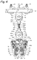
- a pair of I beams 10 are fixed to a ceiling or a stationary beam 11, and horizontal members 12 are fixed to the lower faces of the I beams 10 by bolts 13.
- the support members 4 comprise a base portion 4a and a pair of side walls 4b extending downward from the opposed ends of the base portion 4a, as illustrated in Figs. 4 and 5, and thus have a U-shaped cross-section.
- the base portions 4a of the support members 4 are welded to the lower faces of the corresponding horizontal members 12.
- a cylindrical support pin 14 is fitted into the bores formed in the side walls 4b so that it extends horizontally, and lock pins 15 are fitted into the outwardly projecting ends of the support pin 14.
- Rail clamps 16 are attached to the longitudinal travelling rails 1 at positions beneath the corresponding support members 4.
- Each clamp 16 comprises an upper clamp member 16a and a lower clamp member 16b which are fastened to the longitudinal travelling rail 1 by bolts 17.
- support members 18 are mounded on the upper clamp members 16a.
- Each support member 18 comprises a base portion 18a and a pair of side walls 18b extending upward from the opposed ends of the base portion 18a, as illustrated in Figs. 4 and 5, and thus has a U-shaped cross-section.
- the base portions 18a of the support members 18 are pivotally connected to the corresponding upper clamp members 16a by corresponding pivot pins 19 which have an enlarged top 19a and a nut 19b screwed onto the lower end thereof.
- a cylindrical support pin 20 is fitted into the bores formed in the side walls 18b so that it extends horizontally, and lock pins 21 are fitted into the outwardly projecting ends of the support pin 20.
- each connecting member 3 comprises a threaded rod 22, an upper eyenut 23 and a lower eyenut 24.
- the threaded rod 22 has an upper threaded portion 22a and a lower threaded portion 22b which is threaded in a direction which is opposite to the threaded direction of the upper threaded portion 22a.
- the upper eyenut 23 comprises a base portion 23a and a ring portion 23b.
- the base portion 23a has therein an inner threaded bore 23c (Fig. 7A) into which the threaded portion 22a of the threaded rod 22 is screwed.
- the ring portion 23b has a cylindrical cross-section and has a circular shape opening 23d having an inner diameter which is larger than the outer diameter of the support pin 14.
- the ring portion 23b has a thickness which is smaller than the distance between the side walls 4b of the support member 4.
- the ring portion 23b of the upper eyenut 23 has a cylindrical cross-section
- the support pin 14 also has a cylindrical cross-section. Accordingly, the ring portion 23b is point-contacted with the support pin 14.
- the connecting member 3 since the thickness of the ring portion 23b is smaller than the distance between the side walls 4b of the support member 4, the connecting member 3 is able to swing in all directions with respect to the support member 4. Accordingly, the upper eyenut 23 and the support pin 4 constructs a flexible joint with a point contact.
- the lower eyenut 24 comprises a base portion 24a and a ring portion 24b.
- the base portion 24a has therein an inner threaded bore 24c (Fig. 7A) into which the threaded portion 22b of the threaded rod 22 is screwed.
- the ring portion 24b has a cylindrical cross-section and has a circular shape opening 24d having an inner diameter which is larger than the outer diameter of the support pin 20.
- the ring portion 24b has a thickness which is smaller than the distance between the side walls 18b of the support member 18.
- the ring portion 24b of the lower eyenut 24 has a cylindrical cross-section
- the support pin 20 also has a cylindrical cross-section. Accordingly, the ring portion 24b is point-contacted with the support pin 20.
- the connecting member 3 since the thickness of the ring portion 24b is smaller than the distance between the side walls 18b of the support member 18, the connecting member 3 is able to swing in all directions with respect to the support member 18. Accordingly, the lower eyenut 24 and the support pin 20 also constructs a flexible joint with a point contact.
- Lock nuts 25 and 26 are screwed into the threaded portions 22a and 22b of the threaded rod 22, respectively, and the threaded rod 22 has a pair of cut away portions 27 for receiving a wrench therein.
- the distance between the upper eyenut 23 and the lower eyenut 24 can be adjusted by rotating the threaded rod 22 with the wrench. After the completion of the adjustment, the upper eyenut 23 and the lower eyenut 24 are firmly fixed to the corresponding threaded portions 22a and 22b of the threaded rod 22 by the lock nuts 25 and 26.
- the connecting member 3 shown in Figs. 8A and 8b may be used instead of using the connecting member 3 shown in Figs. 7A and 7B.
- the connecting member 3 illustrated in Figs. 8A and 8B the threaded portions 22a and 22b of the threaded rod 22 are threaded in the same direction.
- the longitudinal travelling rail 1 has, in general, a rectangular cross-section with a slot 28 at the lower face thereof and comprises a horizontally extending flat top wall 1a, a pair of vertical side walls 1b extending downward from the opposed sides of the top wall 1a, a pair of flat flange portions 1c extending horizontally inward from the lower ends of the corresponding side walls 1b, and a pair of end portions 1d projecting upward from the inner ends of the corresponding flange portions 1c and defining the slot 28 therebetween.
- the first free running trolley 5 comprises four wheels 29, and a hanging plate 30 for hanging the transverse travelling rail 2.
- the four wheels 29 comprise two pairs of the two wheels 29 facing with each other.
- the wheels 29 are rotatably supported by corresponding shafts 31 via bearings 32, and the shafts 31 of each pair of the two wheels 29 are obliquely fixed to the opposed side faces of the hanging plate 30 by welding so that the wheels 29 is inclined with respect to the vertical plane, and that the distance between the upper portions of the wheels 29 is smaller than the distance between the lower portions of the wheels 29.
- each wheel 29 has a conical shaped circumferential outer wall 29a so that the outer wall 29a contacts the flange portion 1c over the entire width thereof.
- the transverse travelling rail 2 has a cross-sectional shape which is the same as that of the longitudinal travelling rail 1, and the rail clamps 33 attached to the transverse travelling rail 2 have a construction which is the same as that of the rail clamps 16 attached to the longitudinal travelling rail 1.
- support members 34 pivotally connected to the upper clamp members 33a of the corresponding rail clamps 33 via corresponding pivot pins 35 have a construction which is the same as that of the support members 18 connected the rail clamps 16.
- each support member 34 has a U-shape and is equipped with a support pin 36 having a shape which is the same as that of the support pin 20 of the support member 18.
- Each support pin 36 is loosely fitted into a cylinder bore 37 (Fig. 6) formed in the lower portion of the hanging plate 30.
- each pivot pin 35 has a construction which is the same as that of the pivot pin 19 (Fig. 4).
- the second free running trolley 6 arranged in the transverse travelling rail 2 has a construction which is the same as that of the first free running trolleys 5 arranged in the longitudinal travelling rails 1. Accordingly, the second free running trolley 6 has four inclined wheels 38 and a hanging plate 39 having a shape which is the same as that of the hanging plates 30 of the first free running trolleys 5. As illustrated in Fig. 3, the hoist 7 is hung on the lower portion of the hanging plate 39.
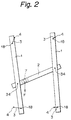
- Figure 2 shows a schematically illustrated plan view of the travelling rail hanging device in case where a force F acts on the hoist 7 to move the position of the hook 9 (Fig. 1) of the hoist 7.
- a force F acts on the hoist 7 to move the position of the hook 9 (Fig. 1) of the hoist 7.
- the longitudinal travelling rails 1 are temporarily swung as illustrated in Fig. 2, and the transverse travelling rail 2 is temporarily swung with respect to the longitudinal travelling rails 2, the free running trolleys 5 and 6 smoothly travel in the corresponding travelling rails 1 and 2 in the direction of the force F. Accordingly, it is possible to smoothly move the hook 9 of the hoist 7 to a target position by an extremely small force.
- the positional relationship between the travelling rails 1 and 2 is returned again to a regular positional relationship such that the longitudinal travelling rails 1 are parallel to each other, and the transverse travelling rail 2 extends approximately at a right angle with respect to the longitudinal travelling rails 1, as illustrated in Fig. 1.
Priority Applications (2)
| Application Number | Priority Date | Filing Date | Title |
|---|---|---|---|
| CA002102585A CA2102585A1 (fr) | 1993-11-05 | 1993-11-05 | Dispositif pour suspendre des rails mobiles |
| EP93118173A EP0656312A1 (fr) | 1993-11-05 | 1993-11-10 | Dispositif de suspension pour rails de guidage |
Applications Claiming Priority (2)
| Application Number | Priority Date | Filing Date | Title |
|---|---|---|---|
| CA002102585A CA2102585A1 (fr) | 1993-11-05 | 1993-11-05 | Dispositif pour suspendre des rails mobiles |
| EP93118173A EP0656312A1 (fr) | 1993-11-05 | 1993-11-10 | Dispositif de suspension pour rails de guidage |
Publications (1)
| Publication Number | Publication Date |
|---|---|
| EP0656312A1 true EP0656312A1 (fr) | 1995-06-07 |
Family
ID=25676487
Family Applications (1)
| Application Number | Title | Priority Date | Filing Date |
|---|---|---|---|
| EP93118173A Withdrawn EP0656312A1 (fr) | 1993-11-05 | 1993-11-10 | Dispositif de suspension pour rails de guidage |
Country Status (2)
| Country | Link |
|---|---|
| EP (1) | EP0656312A1 (fr) |
| CA (1) | CA2102585A1 (fr) |
Cited By (6)
| Publication number | Priority date | Publication date | Assignee | Title |
|---|---|---|---|---|
| EP1205420A1 (fr) * | 2000-11-09 | 2002-05-15 | Grapha-Holding AG | Rail pour contenir un dispositif de roulement pour le transport de marchandises |
| NL2000076C2 (nl) * | 2006-05-15 | 2007-01-23 | Railtechniek Van Herwijnen B V | Transportsysteem voor het manipuleren van objecten, zoals ramen, kozijnen en deuren. |
| WO2007039338A1 (fr) * | 2005-10-01 | 2007-04-12 | Demag Cranes & Components Gmbh | Dispositif pour suspendre un rail, notamment un rail de roulement d'un convoyeur suspendu ou d'un engin de levage |
| JP2020125190A (ja) * | 2019-02-05 | 2020-08-20 | 株式会社ダイフク | 物品搬送設備 |
| CN113800392A (zh) * | 2021-09-27 | 2021-12-17 | 山东中诚机械租赁有限公司 | 一种单轨吊车的悬吊装置 |
| WO2022048973A1 (fr) * | 2020-09-04 | 2022-03-10 | Ocado Innovation Limited | Structure d'ossature de grille |
Citations (3)
| Publication number | Priority date | Publication date | Assignee | Title |
|---|---|---|---|---|
| FR1384261A (fr) * | 1964-01-04 | 1965-01-04 | Demag Zug Gmbh | Gousset pour la suspension de voies de roulement pour palans et installations analogues |
| FR2185578A1 (fr) * | 1972-05-25 | 1974-01-04 | Madeleine Ateli Rs | |
| FR2249023A1 (en) * | 1973-10-25 | 1975-05-23 | Monne Maxime | Tracks for overhead conveyor - spaced apart standard U-sections house rails for wheeled trolleys |
-
1993
- 1993-11-05 CA CA002102585A patent/CA2102585A1/fr not_active Abandoned
- 1993-11-10 EP EP93118173A patent/EP0656312A1/fr not_active Withdrawn
Patent Citations (3)
| Publication number | Priority date | Publication date | Assignee | Title |
|---|---|---|---|---|
| FR1384261A (fr) * | 1964-01-04 | 1965-01-04 | Demag Zug Gmbh | Gousset pour la suspension de voies de roulement pour palans et installations analogues |
| FR2185578A1 (fr) * | 1972-05-25 | 1974-01-04 | Madeleine Ateli Rs | |
| FR2249023A1 (en) * | 1973-10-25 | 1975-05-23 | Monne Maxime | Tracks for overhead conveyor - spaced apart standard U-sections house rails for wheeled trolleys |
Cited By (10)
| Publication number | Priority date | Publication date | Assignee | Title |
|---|---|---|---|---|
| EP1205420A1 (fr) * | 2000-11-09 | 2002-05-15 | Grapha-Holding AG | Rail pour contenir un dispositif de roulement pour le transport de marchandises |
| WO2007039338A1 (fr) * | 2005-10-01 | 2007-04-12 | Demag Cranes & Components Gmbh | Dispositif pour suspendre un rail, notamment un rail de roulement d'un convoyeur suspendu ou d'un engin de levage |
| US7503263B2 (en) | 2005-10-01 | 2009-03-17 | Demag Cranes & Components Gmbh | Device for suspending a rail of an overhead conveyor or a hoisting machine |
| US7784627B2 (en) | 2005-10-01 | 2010-08-31 | Demag Cranes & Components Gmbh | Device for suspending a rail, particularly a running rail of an overhead conveyor or of a lifting apparatus |
| CN101272981B (zh) * | 2005-10-01 | 2012-08-01 | 德马格起重机及部件有限公司 | 用于悬挂导轨的装置 |
| NL2000076C2 (nl) * | 2006-05-15 | 2007-01-23 | Railtechniek Van Herwijnen B V | Transportsysteem voor het manipuleren van objecten, zoals ramen, kozijnen en deuren. |
| JP2020125190A (ja) * | 2019-02-05 | 2020-08-20 | 株式会社ダイフク | 物品搬送設備 |
| WO2022048973A1 (fr) * | 2020-09-04 | 2022-03-10 | Ocado Innovation Limited | Structure d'ossature de grille |
| CN113800392A (zh) * | 2021-09-27 | 2021-12-17 | 山东中诚机械租赁有限公司 | 一种单轨吊车的悬吊装置 |
| CN113800392B (zh) * | 2021-09-27 | 2024-01-09 | 山东中诚机械租赁有限公司 | 一种单轨吊车的悬吊装置 |
Also Published As
| Publication number | Publication date |
|---|---|
| CA2102585A1 (fr) | 1995-05-06 |
Similar Documents
| Publication | Publication Date | Title |
|---|---|---|
| JP2007099517A (ja) | レール、特にオーバヘッドコンベアまたは巻上機の走行レールを懸架するための装置 | |
| KR20150025789A (ko) | 갠트리 크레인장치 | |
| EP0656312A1 (fr) | Dispositif de suspension pour rails de guidage | |
| JPH115683A (ja) | 荷の挟持吊り上げ装置 | |
| US11331817B2 (en) | Maintenance apparatus of robot and maintenance method of robot | |
| CA1238483A (fr) | Methode et systeme d'amenagement d'une carrosserie de vehicule | |
| US4695027A (en) | Industrial robot installation | |
| GB2304681A (en) | Overhead Crane Construction | |
| JP2969539B2 (ja) | ガス絶縁主母線の接続装置 | |
| JP2002114478A (ja) | 自動車用エンジン吊り装置 | |
| US5433150A (en) | Traveling crane | |
| JPH05319773A (ja) | トロリ走行装置 | |
| JP6694774B2 (ja) | 足場用幅木装置 | |
| JPH06147365A (ja) | 管体支持装置および管体接続・離脱方法 | |
| JPH01275398A (ja) | 吊具の2方向傾動装置 | |
| JPH0147365B2 (fr) | ||
| US4372426A (en) | Mast structure | |
| JPH0615979Y2 (ja) | 産業用ロボットの据え付け用補助装置 | |
| CN213197536U (zh) | 倒v型轨道和巡检系统 | |
| JPH059775U (ja) | 溶接機用吊下装置 | |
| KR0124785B1 (ko) | 중장비 엔진의 정비장치 | |
| JP3303951B2 (ja) | 自動旋回フック付き吊り具ブロック | |
| JPH06286990A (ja) | 配管リフトアップ装置及びこれを用いたリフトアップ工法 | |
| JPH1120922A (ja) | 搬送設備 | |
| JP2000159497A (ja) | 箱形重量物の運搬方法および装置 |
Legal Events
| Date | Code | Title | Description |
|---|---|---|---|
| PUAI | Public reference made under article 153(3) epc to a published international application that has entered the european phase |
Free format text: ORIGINAL CODE: 0009012 |
|
| 17P | Request for examination filed |
Effective date: 19931110 |
|
| AK | Designated contracting states |
Kind code of ref document: A1 Designated state(s): BE CH DE DK ES FR GB IT LI NL SE |
|
| STAA | Information on the status of an ep patent application or granted ep patent |
Free format text: STATUS: THE APPLICATION HAS BEEN WITHDRAWN |
|
| 18W | Application withdrawn |
Withdrawal date: 19951208 |