EP0655664A1 - Winding-button with push-piece for a timepiece - Google Patents
Winding-button with push-piece for a timepiece Download PDFInfo
- Publication number
- EP0655664A1 EP0655664A1 EP94118080A EP94118080A EP0655664A1 EP 0655664 A1 EP0655664 A1 EP 0655664A1 EP 94118080 A EP94118080 A EP 94118080A EP 94118080 A EP94118080 A EP 94118080A EP 0655664 A1 EP0655664 A1 EP 0655664A1
- Authority
- EP
- European Patent Office
- Prior art keywords
- push
- head
- button
- spring
- shoulder
- Prior art date
- Legal status (The legal status is an assumption and is not a legal conclusion. Google has not performed a legal analysis and makes no representation as to the accuracy of the status listed.)
- Granted
Links
- 230000006835 compression Effects 0.000 claims description 4
- 238000007906 compression Methods 0.000 claims description 4
- 239000007787 solid Substances 0.000 abstract 2
- 230000007935 neutral effect Effects 0.000 description 7
- 238000010276 construction Methods 0.000 description 4
- 230000008901 benefit Effects 0.000 description 2
- 230000000717 retained effect Effects 0.000 description 2
- 230000009471 action Effects 0.000 description 1
- 230000004323 axial length Effects 0.000 description 1
- 230000008859 change Effects 0.000 description 1
- 230000000295 complement effect Effects 0.000 description 1
- 230000007547 defect Effects 0.000 description 1
- 238000003780 insertion Methods 0.000 description 1
- 230000037431 insertion Effects 0.000 description 1
- 239000004973 liquid crystal related substance Substances 0.000 description 1
- 230000007246 mechanism Effects 0.000 description 1
- 238000007789 sealing Methods 0.000 description 1
- 229910052709 silver Inorganic materials 0.000 description 1
- 239000004332 silver Substances 0.000 description 1
- 230000007704 transition Effects 0.000 description 1
- XLYOFNOQVPJJNP-UHFFFAOYSA-N water Substances O XLYOFNOQVPJJNP-UHFFFAOYSA-N 0.000 description 1
- 238000004804 winding Methods 0.000 description 1
Images


Classifications
-
- G—PHYSICS
- G04—HOROLOGY
- G04B—MECHANICALLY-DRIVEN CLOCKS OR WATCHES; MECHANICAL PARTS OF CLOCKS OR WATCHES IN GENERAL; TIME PIECES USING THE POSITION OF THE SUN, MOON OR STARS
- G04B27/00—Mechanical devices for setting the time indicating means
-
- G—PHYSICS
- G04—HOROLOGY
- G04B—MECHANICALLY-DRIVEN CLOCKS OR WATCHES; MECHANICAL PARTS OF CLOCKS OR WATCHES IN GENERAL; TIME PIECES USING THE POSITION OF THE SUN, MOON OR STARS
- G04B3/00—Normal winding of clockworks by hand or mechanically; Winding up several mainsprings or driving weights simultaneously
- G04B3/04—Rigidly-mounted keys, knobs or crowns
- G04B3/048—Operation exclusively by axial movement of a push-button, e.g. for chronographs
-
- G—PHYSICS
- G04—HOROLOGY
- G04B—MECHANICALLY-DRIVEN CLOCKS OR WATCHES; MECHANICAL PARTS OF CLOCKS OR WATCHES IN GENERAL; TIME PIECES USING THE POSITION OF THE SUN, MOON OR STARS
- G04B37/00—Cases
- G04B37/08—Hermetic sealing of openings, joints, passages or slits
- G04B37/10—Hermetic sealing of openings, joints, passages or slits of winding stems
- G04B37/106—Hermetic sealing of openings, joints, passages or slits of winding stems of push buttons
Definitions
- the present invention relates to a push-button crown suitable for a timepiece, and in particular for high reliability watches.
- the first two positions correspond to the positions that can be taken by a conventional crown.
- the third position (position "-1") is known in 'multi-mode' watches, generally in watches with a first analog display indicating the time and a second display, often digital with liquid crystal, indicating one or more other watch functions such as a second hour or a wake-up time, etc.
- the desired mode can be activated.
- These push-button crowns are fixed to the movement rod so that when the axial or radial position of the push-button crown is changed, the rod is moved axially or radially.
- the push crown in the "0" rest position, the push crown is rigidly connected longitudinally to the rod and can be pulled or pushed.
- the pulled out position (position "1") the push-button crown is also rigidly linked to the rod in order to transmit angular information to the movement, such as for example setting the time by means of this rod.
- this construction is generally known for simple push crowns, that is to say the push crowns having only two positions, the first (which corresponds to position "0") where the rod is free and a second position (which corresponds to position "-1") where the rod is engaged with the movement, allowing for example the time setting.
- a push-button crown is described in the document CH 577 701.
- the push-button crown is also provided with a spring whose advantage is to compensate for a misalignment between itself and the movement.
- This pusher ring does not have the third position (position "1") and is of a relatively simple construction.
- the present invention thus aims to remedy these defects while providing a push-button crown which has the seal suitable for high reliability watches.
- the spring undergoes, in its stable position, a strong precompression so that, after having been brought from its stable position to its fleeting position, it returns completely to its stable position as soon as it is loose, even if the friction due to the seal between the tube and the crown is high.
- the invention also relates to a timepiece characterized in that it comprises a push-button crown as defined above.
- Figure 1 shows an embodiment of the pusher ring according to the invention in its rest position, called position "0".
- the push-button crown 1 is mounted on a middle part C of a watch, preferably high-end, middle part C in the lateral edge of which is mounted a mounting tube T.
- the latter has a flange annular R defining a radial shoulder E1 bearing on a complementary shoulder E2 formed at the mouth of a radial passage P pierced in the edge of the middle part C.
- a seal J preferably in silver is interposed between the shoulders E1 and E2 .
- the tube T also has, near its free end another radial shoulder E3 whose purpose will appear later.
- the tube T is used, in the usual way for the passage of a winding rod TR which can here occupy three positions defined by the movement (not shown) of the watch to which the middle part C.
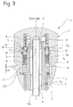
- the three positions of the stem are a neutral position or "0" (figure 1), a drawn position called “+1” (figure 2) in which it allows the time setting of the watch, and a fugitive pushed position called “-1" (FIG. 3) in which it makes it possible to control one or more other functions of the watch, for example by closing an electrical contact (not shown) provided inside the movement.
- the rod also has a usual thread at its free end in order to allow a push-button crown to be made integral therewith.
- the push-button crown 1 comprises a hollow head 2, the bottom of which has a projection 3 provided with a blind hole 4.
- the latter is internally threaded to allow the crown to be screwed onto the end of the rod TR.
- the inner wall of the head 2 has a radial shoulder 5.
- this internal wall has an annular groove 6 with a rounded bottom.
- the head 2 also has an annular groove 7 which is here of rectangular profile.
- a return spring 8 of helical shape is disposed axially in the hollow head 2 and surrounds the projection 3.
- This spring is supported by its inner end on the bottom of the head 2, while its opposite end is supported on a ring stop 9 which surrounds the outer end of the tube T beyond the shoulder E3.
- This ring 9 has an internal flange 10 defining a radial shoulder 11 intended to come into contact with the shoulder E3 of the tube T under the action of the spring 8, at least in the configuration of the push-button crown 1 shown in the figure 1.
- the stop ring 9 has a beveled annular face 12 which is intended to come to bear against a circlip 13 placed in the annular groove 6 of the head 2.
- the ring 9 is in abutment against the circlip 13 in the positions " 0 "and” +1 "of the push-button crown 1.
- the push-button crown according to the invention also comprises a seal made of two rings 14 and 15 of rectangular section and trapped between, on the one hand, a washer 16 bearing against the circlip 13 and, on the other hand , a washer 17 which is in fact a circlip engaged in the groove 7 of the head 2.
- the spring 8 is in a state of precompression while being trapped between the bottom of the head 2 and the shoulder 11.
- it generates an axial force in extension incapable of defeating the forces which maintain the rod TR in its neutral position, forces which are conventionally imposed on this rod by the time-setting mechanism (not shown) of the movement of the watch fitted with the push-button crown according to the invention.
- the precompression can be equal, for example, to 60% of the total clamping force of the spring 8, when all of its turns are clamped against each other.
- the push-button crown according to the invention is intended more particularly to ensure an irreproachable return stroke of the rod TR from its fleeting position "-1" towards its neutral position "0", and this despite the friction forces which can be exerted on this rod by the seal which surrounds it.
- the push-button crown 1 can move on either side of its position "0" over a distance which is preferably the same.
- its axial stroke is the same around this "0" position.
- this stroke is, for example, 0.35 mm, the distance separating the face of the head 2 facing the middle, and the lateral face of the latter being respectively 0.50 mm , 0.85 mm and 0.15 mm depending on whether the push-button crown is in its "0", "+1" and "-1" positions.
- these dimensions essentially depend on the construction of the movement at which the push-button crown is associated and they can therefore vary from one type of movement to another.
- the driving stroke towards the fugitive position "-1" is limited by the shoulder 5 of the head 2.
- the shoulder 5 comes into contact with the stop ring 9 , the spring 8 is compressed so as to provide a return force which is very close to its maximum compression force (Fmax in FIG. 4). It is possible, according to a variant not shown in the figures, to omit the shoulder 5, whereby the end of the driving stroke will be defined by the total compression of the spring 8, all of its turns then being pressed one on the other. others.
- the precompression force F o can be chosen according to the needs. For example, in the case of the use of a push-button crown according to the invention in watches for divers, it is important that the water pressure cannot push the push-button crown. We must then choose this precompression according to the depth that can be reached with the watch. We understand that it is necessary push the push crown relatively hard to reach position "-1" for waterproof watches at a very great depth. In such a case, the precompression F o can be equal to more than 70% of the maximum compression force F max
Landscapes
- Physics & Mathematics (AREA)
- General Physics & Mathematics (AREA)
- Electric Clocks (AREA)
Abstract
Description
La présente invention concerne une couronne-poussoir convenant pour une pièce d'horlogerie, et notamment pour les montres de haute fiabilité.The present invention relates to a push-button crown suitable for a timepiece, and in particular for high reliability watches.
Une couronne-poussoir peut prendre trois positions différentes :
- la position de repos (position "0") dans laquelle la montre marche normalement,
- la position tirée (position "1") dans laquelle on peut régler l'heure de la montre avec la couronne-poussoir qui est liée fixement à la tige, et
- la position poussée (position "-1") dans laquelle la couronne-poussoir ferme brièvement un contact électrique dans la montre.
- the rest position (position "0") in which the watch operates normally,
- the pulled position (position "1") in which the time of the watch can be adjusted with the push-button crown which is fixedly linked to the stem, and
- the pushed position (position "-1") in which the push-button crown briefly closes an electrical contact in the watch.
Les deux premières positions (positions "0" et "1") correspondent aux positions pouvant être prises par une couronne classique.The first two positions (positions "0" and "1") correspond to the positions that can be taken by a conventional crown.
La troisième position (position "-1") est connue dans les montres 'multi-mode', en général dans les montres avec un premier affichage analogique indiquant l'heure et un deuxième affichage, souvent numérique aux cristaux liquides, indiquant une ou plusieurs autres fonctions de la montre telle qu'une deuxième heure ou l'heure de réveil, etc. Ainsi, en actionnant la couronne-poussoir, on peut activer le mode désiré. Ces couronnes-poussoirs sont fixées à la tige des mouvements de telle façon que lorsqu'on change la position axiale ou radiale de la couronne-poussoir, on déplace axialement ou radialement la tige. En effet, en position "0" de repos, la couronne-poussoir est liée de façon rigide longitudinalement à la tige et peut être tirée ou poussée. En position tirée, (position "1") la couronne-poussoir est également liée rigidement à la tige afin de transmettre des informations angulaires au mouvement, comme par exemple la mise à l'heure au moyen de cette tige.The third position (position "-1") is known in 'multi-mode' watches, generally in watches with a first analog display indicating the time and a second display, often digital with liquid crystal, indicating one or more other watch functions such as a second hour or a wake-up time, etc. Thus, by actuating the push-button crown, the desired mode can be activated. These push-button crowns are fixed to the movement rod so that when the axial or radial position of the push-button crown is changed, the rod is moved axially or radially. In fact, in the "0" rest position, the push crown is rigidly connected longitudinally to the rod and can be pulled or pushed. In the pulled out position (position "1") the push-button crown is also rigidly linked to the rod in order to transmit angular information to the movement, such as for example setting the time by means of this rod.
On comprend qu'il est impératif que la couronne-poussoir et la tige reviennent dans la position initiale, parce que si elles restent calées dans la position poussée, ou si elles ne reviennent pas exactement à la position initiale, la montre reste bloquée dans le mode activé.We understand that it is imperative that the push crown and the stem return to the initial position, because if they remain locked in the pushed position, or if they do not return exactly to the initial position, the watch remains blocked in the mode activated.
Une possibilité connue pour faire retourner la tige et sa couronne-poussoir dans leurs positions initiales consiste à placer un ressort de rappel dans la tête de la couronne-poussoir.One known possibility for returning the rod and its push-button crown to their initial positions consists in placing a return spring in the head of the push-button crown.
Toutefois, cette construction est en général connue des couronnes-poussoirs simples, c'est-à-dire les couronnes-poussoirs n'ayant que deux positions, la première (qui correspond à la position "0") où la tige est libre et une deuxième position (qui correspond à la position "-1") ou la tige est embrayée avec le mouvement, permettant par exemple la mise à l'heure. Une telle couronne-poussoir est décrite dans le document CH 577 701. Ici, la couronne-poussoir est également munie d'un ressort dont l'intérêt est de compenser un défaut d'alignement entre elle-même et le mouvement. Cette couronne-poussoir n'a pas la troisième position (position "1") et est d'une construction relativement simple.However, this construction is generally known for simple push crowns, that is to say the push crowns having only two positions, the first (which corresponds to position "0") where the rod is free and a second position (which corresponds to position "-1") where the rod is engaged with the movement, allowing for example the time setting. Such a push-button crown is described in the document CH 577 701. Here, the push-button crown is also provided with a spring whose advantage is to compensate for a misalignment between itself and the movement. This pusher ring does not have the third position (position "1") and is of a relatively simple construction.
Quand on veut augmenter la garantie d'étanchéité de la couronne-poussoir (montre de haute fiabilité), on peut introduire une plus grande garniture d'étanchéité dans la couronne-poussoir. Toutefois, si on introduit une telle garniture, ou si on introduit plusieurs garnitures dans une construction comme décrite ci-avant, le frottement entre la couronne-poussoir et le tube de guidage augmente fortement et on augmente ainsi le risque que la couronne-poussoir ne revienne pas dans sa position inactive à cause de ce frottement.When you want to increase the guarantee of tightness of the push-button crown (high reliability watch), you can introduce a larger seal in the push-button crown. However, if such a lining is introduced, or if several linings are introduced into a construction as described above, the friction between the pusher ring and the guide tube greatly increases and the risk that the pusher ring will therefore increase not return to its inactive position because of this friction.
La présente invention a ainsi pour but de remédier à ces défauts tout en fournissant une couronne-poussoir qui présente l'étanchéité convenant pour les montres de haute fiabilité.The present invention thus aims to remedy these defects while providing a push-button crown which has the seal suitable for high reliability watches.
Ce but est atteint grâce à une couronne-poussoir pour pièce d'horlogerie selon la revendication 1.This object is achieved by means of a push-piece crown for a timepiece according to
Grâce à ces caractéristiques de l'invention, le ressort subit, dans sa position stable, une forte précompression de sorte que, après avoir été amenée de sa position stable vers sa position fugitive, elle revient complètement dans sa position stable dès qu'on la lâche, même si la friction due à la garniture d'étanchéité entre le tube et la couronne, est élevée.Thanks to these characteristics of the invention, the spring undergoes, in its stable position, a strong precompression so that, after having been brought from its stable position to its fleeting position, it returns completely to its stable position as soon as it is loose, even if the friction due to the seal between the tube and the crown is high.
Bien entendu, l'utilisation d'un ressort de rappel fortement précomprimé pour assurer son retour à la position initiale convient également pour les poussoirs en général par exemple à ceux dont l'actionnement ferme un contact électrique.Of course, the use of a highly precompressed return spring to ensure its return to the initial position is also suitable for pushers in general, for example to those whose actuation closes an electrical contact.
L'invention concerne également une pièce d'horlogerie caractérisée en ce qu'elle comprend une couronne-poussoir telle que définie ci-dessus.The invention also relates to a timepiece characterized in that it comprises a push-button crown as defined above.
On va décrire ci-après à titre d'exemple une forme d'exécution de l'objet de l'invention en se référant aux dessins annexés sur lesquels :
- la figure 1 représente la couronne-poussoir selon l'invention dans la position de repos (position "0"),
- la figure 2 représente la couronne-poussoir selon l'invention dans la position tirée (position "+1")
- la figure 3 représente la couronne-poussoir selon l'invention dans la position poussée (position "-1"), et
- la figure 4 montre schématiquement les forces exercées par le ressort de rappel sur la couronne-poussoir selon l'invention en fonction de la position de cette dernière.
- FIG. 1 shows the pusher ring according to the invention in the rest position (position "0"),
- FIG. 2 represents the pusher ring according to the invention in the pulled position (position "+1")
- FIG. 3 shows the pusher ring according to the invention in the pushed position (position "-1"), and
- FIG. 4 schematically shows the forces exerted by the return spring on the push-button crown according to the invention as a function of the position of the latter.
On va d'abord se référer à la figure 1 qui représente un exemple de réalisation de la couronne-poussoir suivant l'invention dans sa position de repos, dite position "0".We will first refer to Figure 1 which shows an embodiment of the pusher ring according to the invention in its rest position, called position "0".
Dans cet exemple, la couronne-poussoir 1 est montée sur une carrure C d'une montre, de préférence de haut de gamme, carrure C dans le bord latéral de laquelle est vissé un tube de montage T. Ce dernier présente un rebord annulaire R définissant un épaulement radial E1 venant en appui sur un épaulement complémentaire E2 ménagé à l'embouchure d'un passage radial P percé dans le bord de la carrure C. Un joint J de préférence en argent est interposé entre les épaulement E1 et E2. Le tube T comporte encore, près de son extrémité libre un autre épaulement radial E3 dont le but apparaître par la suite.In this example, the push-
Le tube T sert, de la façon habituelle au passage d'une tige de remontoir TR qui peut ici occuper trois positions définies par le mouvement (non représenté) de la montre à laquelle appartient la carrure C.The tube T is used, in the usual way for the passage of a winding rod TR which can here occupy three positions defined by the movement (not shown) of the watch to which the middle part C.
Les trois positions de la tige sont une position neutre ou "0" (figure 1), une position tirée dite "+1" (figure 2) dans laquelle elle permet la mise à l'heure de la montre, et une position fugitive poussée dite "-1" (figure 3) dans laquelle elle permet de commander une ou plusieurs autres fonctions de la montre, par exemple par fermeture d'un contact électrique (non représenté) prévu à l'intérieur du mouvement.The three positions of the stem are a neutral position or "0" (figure 1), a drawn position called "+1" (figure 2) in which it allows the time setting of the watch, and a fugitive pushed position called "-1" (FIG. 3) in which it makes it possible to control one or more other functions of the watch, for example by closing an electrical contact (not shown) provided inside the movement.
La tige comporte également un filetage habituel à son extrémité libre afin de permettre d'en rendre solidaire une couronne-poussoir.The rod also has a usual thread at its free end in order to allow a push-button crown to be made integral therewith.
Il est à noter que la disposition que l'on vient de décrire est classique et ne fait pas partie de l'invention. Il est à noter également que pour que l'invention trouve son application, il n'est pas nécessaire que la tige TR puisse occuper la position tirée, l'intérêt de l'invention résidant dans un meilleur rappel de la tige et de la couronne-poussoir de la position poussée "-1" vers la position neutre "0".It should be noted that the arrangement which has just been described is conventional and does not form part of the invention. It should also be noted that for the invention to find its application, it is not necessary for the rod TR to be able to occupy the pulled position, the advantage of the invention residing in a better recall of the rod and of the crown. - push-button from pushed position "-1" to neutral position "0".
Ceci étant, suivant l'invention, la couronne-poussoir 1 comprend une tête creuse 2 dont le fond présente une saillie 3 munie d'un trou borgne 4. Ce dernier est fileté intérieurement pour permettre le vissage de la couronne sur l'extrémité de la tige TR. Dans cet exemple on voit qu'à peu près à mi-longueur axiale, la paroi intérieur de la tête 2 comporte un épaulement radial 5. Plus loin vers l'extrémité ouverte de la tête 2, cette paroi interne présente une rainure annulaire 6 à fond arrondi. Enfin, prés de sa sortie, la tête 2 comporte encore une rainure annulaire 7 qui est ici de profil rectangulaire.However, according to the invention, the push-
Un ressort de rappel 8 de forme hélicoïdale est disposé axialement dans la tête creuse 2 et entoure la saillie 3. Ce ressort prend appui, par son extrémité intérieure sur le fond de la tête 2, tandis que son extrémité opposée est en appui sur une bague de butée 9 qui entoure l'extrémité extérieure du tube T au delà de l'épaulement E3. Cette bague 9 comporte une collerette interne 10 définissant un épaulement radial 11 destiné à venir en contact de l'épaulement E3 du tube T sous l'action du ressort 8, tout au moins dans la configuration de la couronne-poussoir 1 représentée sur la figure 1.A
Extérieurement, la bague de butée 9 présente une face annulaire biseautée 12 qui est destinée à venir s'appliquer contre un circlips 13 placé dans la rainure annulaire 6 de la tête 2. La bague 9 est en appui contre le circlips 13 dans les positions "0" et "+1" de la couronne-poussoir 1.Externally, the
La couronne-poussoir selon l'invention comporte encore une garniture d'étanchéité faite de deux anneaux 14 et 15 de section rectangulaire et emprisonnés entre, d'une part, une rondelle 16 venant en appui contre le circlips 13 et, d'autre part, une rondelle 17 qui est en fait une circlips engagé dans la rainure 7 de la tête 2.The push-button crown according to the invention also comprises a seal made of two
Il est à noter que, dans les configurations de la couronne-poussoir représentées sur les figures 1 et 2, le ressort 8 est dans un état de précompression en étant emprisonné entre le fond de la tête 2 et l'épaulement 11. Ainsi, il engendre une force axiale en extension incapable de vaincre les forces qui maintiennent la tige TR dans sa position neutre, forces qui sont, de façon classique, imposées à cette tige par le mécanisme de mise à l'heure (non représenté) du mouvement de la montre équipée de la couronne-poussoir selon l'invention. Bien entendu, ceci est également vrai pour la position tirée "+1" de la tige TR retenue en général à l'intérieur du mouvement par une butée axiale empêchant la tige TR de se désolidariser du mouvement. La précompression peut être égale par exemple à 60% de la force de serrage totale du ressort 8, lorsque toutes ses spires sont serrées les unes contre les autres.It should be noted that, in the configurations of the push crown represented in FIGS. 1 and 2, the
On va maintenant décrire le fonctionnement de la couronne-poussoir 1 selon l'invention en examinant successivement les figures 1, 2 et 3, à l'aide du graphique explicatif de la figure 4.We will now describe the operation of the push-
Il a déjà été indiqué ci-dessus que la couronne-poussoir selon l'invention est destinée plus particulièrement à assurer une course de rappel irréprochable de la tige TR à partir de sa position fugitive "-1" vers sa position neutre "0", et ce malgré les forces de friction qui peuvent être exercées sur cette tige par la garniture d'étanchéité qui l'entoure.It has already been indicated above that the push-button crown according to the invention is intended more particularly to ensure an irreproachable return stroke of the rod TR from its fleeting position "-1" towards its neutral position "0", and this despite the friction forces which can be exerted on this rod by the seal which surrounds it.
On remarquera que dans l'exemple décrit ici, la couronne-poussoir 1 peut se déplacer de part et d'autre de sa position "0" sur une distance qui est de préférence la même. En d'autres termes, sa course axiale est la même autour de cette position "0". Sur les figures, cette course est, à titre d'exemple, de 0,35 mm, la distance séparant la face de la tête 2 en regard de la carrure , et la face latérale de celle-ci étant respectivement de 0,50 mm, de 0,85 mm et de 0,15 mm suivant que la couronne-poussoir se trouve dans ses positions "0", "+1" et "-1".Bien entendu, ces dimensions dépendent essentiellement de la construction du mouvement auquel la couronne-poussoir est associée et elles peuvent donc varier d'un type de mouvement à l'autre.It will be noted that in the example described here, the push-
Dans la position "0" de la figure 1, le ressort 8 est sous précompression et il tend donc à écarter le fond de la tête 2 de la face de la bague de butée 9 contre laquelle il est en appui. De ce fait, la bague de butée 9 est appuyée non seulement contre le circlips 13, mais également contre l'épaulement E3 du tube T. Ainsi, cette position "0" est parfaitement stable.In the "0" position of FIG. 1, the
Si maintenant, l'utilisateur déplace l'ensemble tige TR et couronne-poussoir 1 vers l'extérieur, afin de pouvoir effectuer une commande de mise à l'heure de la montre par exemple, il tire sure la couronne-poussoir 1, ce qui fait se déplacer l'ensemble axialement d'une même translation par rapport à la carrure C. (Passage de la position "0" de la figure 1 vers la position "+1" de la figure 2. De ce fait rien ne change pour le ressort 8 qui reste tendu entre ses butées avec la même précompression. En revanche, on notera que la bague de butée 9 s'est levée de son épaulement E3 du tube T. On voit donc que la tige TR s'est déplacée axialement par rapport à la carrure C. Il est à noter que pendant ce déplacement, la garniture d'étanchéité formée des anneaux 14 et 15 s'est déplacée par rapport au tube T, mais ce déplacement n'engendre aucune gêne pour le bon fonctionnement, puisque les forces de friction sont ici vaincues par l'utilisateur de la montre.If the user now moves the stem TR and push-
Par conséquent, la force de rappel due au ressort 8 reste nulle et elle n'évolue pas entre les deux positions que l'on vient d'examiner. (partie droite du graphique de la figure 4).Consequently, the restoring force due to the
Il en va tout autrement, lorsque l'on passe de la position neutre "0" de la figure 1 à la position fugitive "-1" de la figure 3. Dans ce cas, en effet, la bague de butée 9 est axialement retenue par l'épaulement E3 du tube T, de sorte que, dès que la tête 2 est déplacée axialement vers la carrure C, le ressort 8 va être comprimé davantage qu'il ne l'était dans son état de précompression. Cependant, la force résistante du ressort ou en d'autres termes sa force de rappel est alors d'emblée égale à la valeur de la force de précompression Fo, c'est-à-dire dès que le circlips 13 se détaché de la bague de butée 9. En poursuivant la course, cette force de rappel ne fait qu'augmenter selon la constante du ressort.It is quite different, when we pass from the neutral position "0" in Figure 1 to the fleeting position "-1" in Figure 3. In this case, in fact, the
On voit donc qu'il y a une transition brusque dans l'évolution de la force de rappel au début de la course d'enfoncement de la couronne-poussoir (partie de gauche du graphique de la figure 4). Cette brusque augmentation loin d'être gênante pour l'utilisateur (car il s'agit de toute manière de forces relativement faible), elle est en revanche très utile pour ramener la couronne-poussoir 1 et la tige TR à la position neutre de la figure 1.We therefore see that there is an abrupt transition in the evolution of the restoring force at the start of the push-in stroke of the push-button crown (left part of the graph in Figure 4). This sudden increase far from being annoying for the user (because it is anyway relatively low forces), it is however very useful to bring the push-
En effet, lors de l'enfoncement, on voit que les anneaux 14 et 15 fortement appuyés contre le tube T pour garantir la bonne étanchéité, glissent sur le tube T. Mais comme le ressort 8 rappèle l'ensemble avec une force qui se compose de la force de précompression à laquelle s'ajoute la force de déformation dynamique du ressort, le retour vers la position neutre ne pose aucun problème, la friction des anneaux sur le tube T étant facilement vaincue.Indeed, during insertion, we see that the
Dans le mode de réalisation décrit, la course d'enfoncement vers la position fugitive "-1", est limitée par l'épaulement 5 de la tête 2. Lorsque comme représenté, l'épaulement 5 vient en contact avec la bague de butée 9, le ressort 8 est comprimé de manière à fournir une force de rappel qui est très proche de sa force de compression maximale (Fmax sur la figure 4). Il est possible, selon une variante non-représentée aux figures, d'omettre l'épaulement 5, moyennant quoi la fin de la course d'enfoncement sera définie par la compression totale du ressort 8, toutes ses spires étant alors appuyées les unes sur les autres.In the embodiment described, the driving stroke towards the fugitive position "-1" is limited by the
Avantageusement, on peut choisir la force de précompression Fo en fonction des besoins. Par exemple, dans le cas de l'utilisation d'une couronne-poussoir selon l'invention dans des montres pour plongeur, il est important que la pression de l'eau ne puisse pas enfoncer la couronne-poussoir. On doit alors choisir cette précompression en fonction de la profondeur qui peut être atteinte avec la montre. On comprend ainsi qu'il faut pousser relativement fortement la couronne-poussoir pour atteindre la position "-1" pour les montres étanches à une très grande profondeur. Dans un tel cas, la précompression Fo peut être égale à plus de 70 % de la force de compression maximale Fmax Advantageously, the precompression force F o can be chosen according to the needs. For example, in the case of the use of a push-button crown according to the invention in watches for divers, it is important that the water pressure cannot push the push-button crown. We must then choose this precompression according to the depth that can be reached with the watch. We understand that it is necessary push the push crown relatively hard to reach position "-1" for waterproof watches at a very great depth. In such a case, the precompression F o can be equal to more than 70% of the maximum compression force F max
Claims (7)
Applications Claiming Priority (2)
| Application Number | Priority Date | Filing Date | Title |
|---|---|---|---|
| CH03531/93A CH685901B5 (en) | 1993-11-25 | 1993-11-25 | Crown-button timepiece. |
| CH3531/93 | 1993-11-25 |
Publications (2)
| Publication Number | Publication Date |
|---|---|
| EP0655664A1 true EP0655664A1 (en) | 1995-05-31 |
| EP0655664B1 EP0655664B1 (en) | 1997-05-02 |
Family
ID=4258009
Family Applications (1)
| Application Number | Title | Priority Date | Filing Date |
|---|---|---|---|
| EP94118080A Expired - Lifetime EP0655664B1 (en) | 1993-11-25 | 1994-11-17 | Winding-button with push-piece for a timepiece |
Country Status (10)
| Country | Link |
|---|---|
| US (1) | US5521890A (en) |
| EP (1) | EP0655664B1 (en) |
| JP (1) | JP3479132B2 (en) |
| KR (1) | KR100355183B1 (en) |
| CN (1) | CN1050910C (en) |
| CH (1) | CH685901B5 (en) |
| DE (1) | DE69402945T2 (en) |
| HK (1) | HK1007808A1 (en) |
| SG (1) | SG88717A1 (en) |
| TW (1) | TW259852B (en) |
Cited By (6)
| Publication number | Priority date | Publication date | Assignee | Title |
|---|---|---|---|---|
| WO1999047984A1 (en) * | 1998-03-18 | 1999-09-23 | Konrad Damasko | Actuation or adjustment member for watches, especially wristwatches |
| EP0957415A1 (en) * | 1998-05-14 | 1999-11-17 | Eta SA Fabriques d'Ebauches | Push-button device for timepiece,especially chronograph |
| US6227700B1 (en) | 1998-05-13 | 2001-05-08 | Eta Sa Fabriques D'ebauches | Push button device for a timepiece, in particular a chronograph |
| EP2107432A1 (en) * | 2008-04-01 | 2009-10-07 | Montres Rado S.A. | Pushbutton control device for a watch |
| EP2746870A1 (en) | 2012-12-18 | 2014-06-25 | Meco S.A. | Dismountable crown |
| CN103995457A (en) * | 2013-02-20 | 2014-08-20 | 精工电子有限公司 | Portable device and portable timepiece |
Families Citing this family (29)
| Publication number | Priority date | Publication date | Assignee | Title |
|---|---|---|---|---|
| IT1285148B1 (en) * | 1996-06-03 | 1998-06-03 | Panerai Off Srl | DEVICE FOR LOCKING THE ROTATING BEZEL OF WATCHES, IN PARTICULAR DIVING WATCHES, AND FOR WATER-SEALING THE CROWN |
| FI19992510A (en) * | 1999-11-24 | 2001-05-25 | Nokia Mobile Phones Ltd | Electronic device and method in the electronic device |
| CH705218B1 (en) * | 1999-12-02 | 2013-01-15 | Ks 22 S A | method of mounting a crown screwed on a watch case. |
| US6453301B1 (en) | 2000-02-23 | 2002-09-17 | Sony Corporation | Method of using personal device with internal biometric in conducting transactions over a network |
| WO2001071478A2 (en) * | 2000-03-22 | 2001-09-27 | Sony Electronics Inc | Data entry user interface |
| US20020026419A1 (en) * | 2000-08-24 | 2002-02-28 | Sony Electronics, Inc. | Apparatus and method for populating a portable smart device |
| US7251633B2 (en) * | 2000-12-11 | 2007-07-31 | Sony Corporation | Method or system for executing deferred transactions |
| US7765163B2 (en) * | 2000-12-12 | 2010-07-27 | Sony Corporation | System and method for conducting secure transactions over a network |
| US20020124190A1 (en) * | 2001-03-01 | 2002-09-05 | Brian Siegel | Method and system for restricted biometric access to content of packaged media |
| DE60137213D1 (en) * | 2001-07-28 | 2009-02-12 | Richemont Int Sa | Waterproof crown for watch case |
| JP2003222688A (en) * | 2002-01-30 | 2003-08-08 | Seiko Instruments Inc | Portable watch |
| FI124328B (en) * | 2008-12-31 | 2014-06-30 | Suunto Oy | Two-function control means for a wrist computer or equivalent and a method for controlling a wrist computer or a corresponding terminal device |
| JP5405945B2 (en) * | 2009-08-28 | 2014-02-05 | セイコーインスツル株式会社 | Cell phone clock |
| JP5279661B2 (en) * | 2009-08-28 | 2013-09-04 | セイコーインスツル株式会社 | Cell phone clock |
| JP5285547B2 (en) * | 2009-08-28 | 2013-09-11 | セイコーインスツル株式会社 | Cell phone clock |
| CH705090A2 (en) * | 2011-06-08 | 2012-12-14 | Omega Sa | Device for adjusting angular orientation of screw-down crown relative to middle of watch, has indexing unit arranged between cover and coupling member of crown, and magnetic return unit to rotatably connect cover and coupling member |
| JP5876316B2 (en) * | 2012-02-07 | 2016-03-02 | セイコーインスツル株式会社 | Portable devices and portable watches |
| JP6551662B2 (en) * | 2015-06-12 | 2019-07-31 | セイコーエプソン株式会社 | Electronic device including push button and push button |
| JP6394563B2 (en) * | 2015-10-21 | 2018-09-26 | カシオ計算機株式会社 | Switch device and clock |
| CN106933084A (en) * | 2016-11-07 | 2017-07-07 | 东莞市亿丰钟表有限公司 | Waterproof intelligent watch |
| EP3339966B1 (en) * | 2016-12-23 | 2020-06-24 | Rolex Sa | Push-button for a timepiece |
| EP3612899B1 (en) * | 2017-04-18 | 2023-08-09 | Timex Group USA, Inc. | Crown pusher assembly and wristwearable electronic device comprising same |
| US10725429B2 (en) * | 2017-05-24 | 2020-07-28 | Omega Sa | Timepiece containing a locking device for a pusher |
| CH713979A2 (en) * | 2017-07-14 | 2019-01-15 | Swatch Group Res & Dev Ltd | Security valve for watch. |
| EP3454137B1 (en) * | 2017-09-07 | 2024-03-06 | Montres Breguet S.A. | Hand tool for actuating a push-button corrector provided in a watch |
| EP3454138B1 (en) * | 2017-09-07 | 2024-02-21 | Montres Breguet S.A. | Hand tool for actuating a push-button corrector provided in a watch |
| EP3805871B1 (en) * | 2019-10-09 | 2024-01-17 | Meco S.A. | Adjustable threaded crown |
| EP3828641B1 (en) * | 2019-11-29 | 2022-07-20 | Meco S.A. | Push-crown for a timepiece |
| CN112984502A (en) * | 2021-01-27 | 2021-06-18 | 杭州聚能环保科技股份有限公司 | Micro-discharge pulverized coal combustion system |
Citations (3)
| Publication number | Priority date | Publication date | Assignee | Title |
|---|---|---|---|---|
| CH239240A (en) * | 1943-04-27 | 1945-09-30 | Simon John | Waterproof timepiece pusher. |
| CH239783A (en) * | 1942-01-15 | 1945-11-15 | Colomb Henri | Waterproof pusher. |
| CH678138B5 (en) * | 1989-04-13 | 1992-02-14 | Charles Wilhelm & Cie S A |
Family Cites Families (5)
| Publication number | Priority date | Publication date | Assignee | Title |
|---|---|---|---|---|
| CH577701B5 (en) * | 1973-05-04 | 1976-07-15 | Nationale Sa | |
| FR2420834A1 (en) * | 1978-03-24 | 1979-10-19 | Suisse Horlogerie | PUSHBUTTON SWITCH FOR WATCH PART |
| CH630771B (en) * | 1979-07-04 | Boninchi Sa | CONTROL UNIT FOR WATERPROOF WATCH. | |
| JPS6042393Y2 (en) * | 1980-01-24 | 1985-12-26 | シチズン時計株式会社 | Waterproof reuse device for quartz watches |
| CH682199B5 (en) * | 1992-02-07 | 1994-02-15 | Smh Management Services Ag | Safety valve for a timepiece diver. |
-
1993
- 1993-11-25 CH CH03531/93A patent/CH685901B5/en not_active IP Right Cessation
-
1994
- 1994-10-21 TW TW083109779A patent/TW259852B/zh active
- 1994-10-21 US US08/326,963 patent/US5521890A/en not_active Expired - Lifetime
- 1994-11-11 KR KR1019940029480A patent/KR100355183B1/en not_active IP Right Cessation
- 1994-11-17 EP EP94118080A patent/EP0655664B1/en not_active Expired - Lifetime
- 1994-11-17 DE DE69402945T patent/DE69402945T2/en not_active Expired - Lifetime
- 1994-11-17 SG SG9605864A patent/SG88717A1/en unknown
- 1994-11-21 JP JP28646194A patent/JP3479132B2/en not_active Expired - Fee Related
- 1994-11-24 CN CN94118813A patent/CN1050910C/en not_active Expired - Fee Related
-
1998
- 1998-06-26 HK HK98106896A patent/HK1007808A1/en not_active IP Right Cessation
Patent Citations (3)
| Publication number | Priority date | Publication date | Assignee | Title |
|---|---|---|---|---|
| CH239783A (en) * | 1942-01-15 | 1945-11-15 | Colomb Henri | Waterproof pusher. |
| CH239240A (en) * | 1943-04-27 | 1945-09-30 | Simon John | Waterproof timepiece pusher. |
| CH678138B5 (en) * | 1989-04-13 | 1992-02-14 | Charles Wilhelm & Cie S A |
Cited By (9)
| Publication number | Priority date | Publication date | Assignee | Title |
|---|---|---|---|---|
| WO1999047984A1 (en) * | 1998-03-18 | 1999-09-23 | Konrad Damasko | Actuation or adjustment member for watches, especially wristwatches |
| US6227700B1 (en) | 1998-05-13 | 2001-05-08 | Eta Sa Fabriques D'ebauches | Push button device for a timepiece, in particular a chronograph |
| EP0957415A1 (en) * | 1998-05-14 | 1999-11-17 | Eta SA Fabriques d'Ebauches | Push-button device for timepiece,especially chronograph |
| EP2107432A1 (en) * | 2008-04-01 | 2009-10-07 | Montres Rado S.A. | Pushbutton control device for a watch |
| US7967504B2 (en) | 2008-04-01 | 2011-06-28 | Montres Rado S.A. | Push-button control device for a watch |
| EP2746870A1 (en) | 2012-12-18 | 2014-06-25 | Meco S.A. | Dismountable crown |
| US9229431B2 (en) | 2012-12-18 | 2016-01-05 | Meco Sa | Removable crown |
| CN103995457A (en) * | 2013-02-20 | 2014-08-20 | 精工电子有限公司 | Portable device and portable timepiece |
| CN103995457B (en) * | 2013-02-20 | 2017-10-24 | 精工电子有限公司 | Portable equipment and portable watch |
Also Published As
| Publication number | Publication date |
|---|---|
| KR950015013A (en) | 1995-06-16 |
| DE69402945D1 (en) | 1997-06-05 |
| CN1111765A (en) | 1995-11-15 |
| KR100355183B1 (en) | 2002-12-16 |
| CH685901GA3 (en) | 1995-11-15 |
| TW259852B (en) | 1995-10-11 |
| US5521890A (en) | 1996-05-28 |
| JP3479132B2 (en) | 2003-12-15 |
| DE69402945T2 (en) | 1997-11-20 |
| CN1050910C (en) | 2000-03-29 |
| HK1007808A1 (en) | 1999-04-23 |
| CH685901B5 (en) | 1996-05-15 |
| JPH07198863A (en) | 1995-08-01 |
| SG88717A1 (en) | 2002-05-21 |
| EP0655664B1 (en) | 1997-05-02 |
Similar Documents
| Publication | Publication Date | Title |
|---|---|---|
| EP0655664B1 (en) | Winding-button with push-piece for a timepiece | |
| EP1676177B1 (en) | Wristwatch push-piece winding button control device | |
| CH700818B1 (en) | portable device and watch. | |
| CH712804B1 (en) | Timepiece with retractable pusher. | |
| EP0555762A1 (en) | Push-button for diver's timepiece | |
| EP1048988A2 (en) | Locking device for a watch winding button | |
| EP3432085A1 (en) | Safety valve for a timepiece | |
| CH710110B1 (en) | Timepiece. | |
| EP1285313B1 (en) | Push-piece control device for a watch | |
| EP3742235B1 (en) | Push button system, and timepiece comprising same | |
| EP1916577A2 (en) | Screwing crown | |
| FR2471626A1 (en) | MINIATURE PUSHER | |
| CH688495GA3 (en) | Timepiece including a pull rod and drive mechanism. | |
| EP3650951A1 (en) | Timepiece comprising a device for locking a valve or a crown | |
| FR2461291A1 (en) | CONTROL UNIT FOR WATERPROOF WATCH | |
| EP4092490A1 (en) | Device for controlling a timepiece movement with touch return and timepiece, in particular a watch, including such a device | |
| FR2931137A1 (en) | DEVICE FOR DISPENSING FLUID PRODUCT | |
| CH708126A2 (en) | Seal, and push crown timepiece. | |
| CH639663A5 (en) | Pteridine compounds possessing pharmaceutical activity | |
| EP4266130A1 (en) | Control member of at least one first function of a timepiece movement | |
| CH718645A2 (en) | Device for controlling a watch movement with tactile feedback and timepiece, in particular a watch, comprising such a device. | |
| CH700635B1 (en) | Watch bezel control device. | |
| EP4231100A1 (en) | Timepiece control device | |
| CH718371A2 (en) | Watch fitted with a device for locking an external control device. | |
| EP1801673B1 (en) | Security device for control mechanism of a watch |
Legal Events
| Date | Code | Title | Description |
|---|---|---|---|
| PUAI | Public reference made under article 153(3) epc to a published international application that has entered the european phase |
Free format text: ORIGINAL CODE: 0009012 |
|
| AK | Designated contracting states |
Kind code of ref document: A1 Designated state(s): DE FR GB IT |
|
| 17P | Request for examination filed |
Effective date: 19950617 |
|
| GRAG | Despatch of communication of intention to grant |
Free format text: ORIGINAL CODE: EPIDOS AGRA |
|
| 17Q | First examination report despatched |
Effective date: 19960701 |
|
| GRAH | Despatch of communication of intention to grant a patent |
Free format text: ORIGINAL CODE: EPIDOS IGRA |
|
| GRAH | Despatch of communication of intention to grant a patent |
Free format text: ORIGINAL CODE: EPIDOS IGRA |
|
| GRAA | (expected) grant |
Free format text: ORIGINAL CODE: 0009210 |
|
| AK | Designated contracting states |
Kind code of ref document: B1 Designated state(s): DE FR GB IT |
|
| REF | Corresponds to: |
Ref document number: 69402945 Country of ref document: DE Date of ref document: 19970605 |
|
| GBT | Gb: translation of ep patent filed (gb section 77(6)(a)/1977) |
Effective date: 19970725 |
|
| PLBE | No opposition filed within time limit |
Free format text: ORIGINAL CODE: 0009261 |
|
| STAA | Information on the status of an ep patent application or granted ep patent |
Free format text: STATUS: NO OPPOSITION FILED WITHIN TIME LIMIT |
|
| 26N | No opposition filed | ||
| REG | Reference to a national code |
Ref country code: GB Ref legal event code: IF02 |
|
| PGFP | Annual fee paid to national office [announced via postgrant information from national office to epo] |
Ref country code: IT Payment date: 20061130 Year of fee payment: 13 |
|
| PGFP | Annual fee paid to national office [announced via postgrant information from national office to epo] |
Ref country code: GB Payment date: 20081029 Year of fee payment: 15 |
|
| PG25 | Lapsed in a contracting state [announced via postgrant information from national office to epo] |
Ref country code: IT Free format text: LAPSE BECAUSE OF NON-PAYMENT OF DUE FEES Effective date: 20071117 |
|
| GBPC | Gb: european patent ceased through non-payment of renewal fee |
Effective date: 20091117 |
|
| PG25 | Lapsed in a contracting state [announced via postgrant information from national office to epo] |
Ref country code: GB Free format text: LAPSE BECAUSE OF NON-PAYMENT OF DUE FEES Effective date: 20091117 |
|
| PGFP | Annual fee paid to national office [announced via postgrant information from national office to epo] |
Ref country code: DE Payment date: 20101025 Year of fee payment: 17 |
|
| PGFP | Annual fee paid to national office [announced via postgrant information from national office to epo] |
Ref country code: FR Payment date: 20130107 Year of fee payment: 19 |
|
| REG | Reference to a national code |
Ref country code: DE Ref legal event code: R119 Ref document number: 69402945 Country of ref document: DE Effective date: 20130601 |
|
| PG25 | Lapsed in a contracting state [announced via postgrant information from national office to epo] |
Ref country code: DE Free format text: LAPSE BECAUSE OF NON-PAYMENT OF DUE FEES Effective date: 20130601 |
|
| REG | Reference to a national code |
Ref country code: FR Ref legal event code: ST Effective date: 20140731 |
|
| PG25 | Lapsed in a contracting state [announced via postgrant information from national office to epo] |
Ref country code: FR Free format text: LAPSE BECAUSE OF NON-PAYMENT OF DUE FEES Effective date: 20131202 |