EP4266130A1 - Control member of at least one first function of a timepiece movement - Google Patents
Control member of at least one first function of a timepiece movement Download PDFInfo
- Publication number
- EP4266130A1 EP4266130A1 EP22169142.1A EP22169142A EP4266130A1 EP 4266130 A1 EP4266130 A1 EP 4266130A1 EP 22169142 A EP22169142 A EP 22169142A EP 4266130 A1 EP4266130 A1 EP 4266130A1
- Authority
- EP
- European Patent Office
- Prior art keywords
- cam
- crown
- function
- control member
- guide tube
- Prior art date
- Legal status (The legal status is an assumption and is not a legal conclusion. Google has not performed a legal analysis and makes no representation as to the accuracy of the status listed.)
- Pending
Links
- 230000007935 neutral effect Effects 0.000 claims abstract description 36
- 230000000994 depressogenic effect Effects 0.000 claims description 10
- 230000000295 complement effect Effects 0.000 claims description 7
- PEDCQBHIVMGVHV-UHFFFAOYSA-N Glycerine Chemical compound OCC(O)CO PEDCQBHIVMGVHV-UHFFFAOYSA-N 0.000 description 1
- KJFBVJALEQWJBS-XUXIUFHCSA-N maribavir Chemical compound CC(C)NC1=NC2=CC(Cl)=C(Cl)C=C2N1[C@H]1O[C@@H](CO)[C@H](O)[C@@H]1O KJFBVJALEQWJBS-XUXIUFHCSA-N 0.000 description 1
Images

Classifications
-
- G—PHYSICS
- G04—HOROLOGY
- G04B—MECHANICALLY-DRIVEN CLOCKS OR WATCHES; MECHANICAL PARTS OF CLOCKS OR WATCHES IN GENERAL; TIME PIECES USING THE POSITION OF THE SUN, MOON OR STARS
- G04B3/00—Normal winding of clockworks by hand or mechanically; Winding up several mainsprings or driving weights simultaneously
- G04B3/04—Rigidly-mounted keys, knobs or crowns
- G04B3/046—Operation by rotation and axial movement with extra function of axial shift of operating element, e.g. crown combined with push button
-
- G—PHYSICS
- G04—HOROLOGY
- G04B—MECHANICALLY-DRIVEN CLOCKS OR WATCHES; MECHANICAL PARTS OF CLOCKS OR WATCHES IN GENERAL; TIME PIECES USING THE POSITION OF THE SUN, MOON OR STARS
- G04B27/00—Mechanical devices for setting the time indicating means
- G04B27/005—Mechanical devices for setting the time indicating means stepwise or on determined values
-
- G—PHYSICS
- G04—HOROLOGY
- G04F—TIME-INTERVAL MEASURING
- G04F7/00—Apparatus for measuring unknown time intervals by non-electric means
- G04F7/04—Apparatus for measuring unknown time intervals by non-electric means using a mechanical oscillator
- G04F7/08—Watches or clocks with stop devices, e.g. chronograph
- G04F7/0804—Watches or clocks with stop devices, e.g. chronograph with reset mechanisms
Definitions
- the present invention relates to a control member for at least a first function of a watch movement, said control member comprising a crown comprising a head and a central rod secured to the head and intended to be secured to a control rod, and a guide tube with longitudinal axis A in which said central rod is mounted movable at least in axial rotation along said axis A, the crown being arranged to occupy at least one non-pressed position in which said crown is movable in axial rotation in at least one direction between at least one neutral, stable angular position, and at least one unstable actuation angular position in which said first function is capable of being actuated via the control rod.
- the present invention also relates to a timepiece comprising at least one such control member.
- Such a control member is used for example in a timepiece described in the application PCT/EP2022/051007 filed by the applicant, said timepiece comprising in particular a month indicator mechanism, the first function being a month correction function.
- the control member in the non-pressed position, is movable in axial rotation, for example through an angle of approximately 60°, in one direction between its central stable angular position and a first unstable actuation angular position, corresponding to a rapid correction of month +1, and an angle of approximately 60° in the other direction between its central stable angular position and a second unstable actuation angular position corresponding to a rapid correction of month -1.
- the timepiece described in the application PCT/EP2022/051007 also comprises a chronograph mechanism, the control member also being arranged to, in response to pressure, be movable in axial translation between its non-pressed position and a pressed position in which a second function is activated, namely one of the chronograph functions, and more particularly the Reset or Flyback function.
- the control member automatically returns to its non-pressed position after releasing the pressure on the control member, like a pusher.
- a mechanism comprising a heart cam linked kinematically to the control member and returned to its central position by a spring once the torque applied to the released control member and the correction made.
- the present invention aims to remedy this drawback by proposing a control member making it possible to guarantee its automatic return to a neutral position after having been pivoted into an unstable position to activate a function of a watch movement, such as rapid correction.
- Another aim of the present invention is to propose a single control member allowing rapid control of a first function by rotation of the control member with an automatic return to the neutral position, like a control rod fast, and also making it possible to activate a second function, different from the first function, by pressing on said control member with an automatic return to the non-pressed position, like a pusher.
- the invention relates to a control member for at least one function of a watch movement, said control member comprising a crown comprising a head and a central rod secured to the head and intended to be secured to a rod control tube, and a guide tube with longitudinal axis A in which said central rod is mounted movable at least in axial rotation along said longitudinal axis A, the crown being arranged to occupy at least one non-pressed position in which said crown is movable in axial rotation in at least one direction between at least one neutral, stable angular position, and at least one unstable angular actuation position in which said first function is capable of being actuated via the control rod.
- the control member comprises a device for automatically returning the crown from its actuation position to its neutral position comprising a first tubular cam mounted integrally around the central rod and a second tubular cam housed in the tube guide, mounted freely in axial translation on the central rod and arranged to be able to essentially slide axially in said guide tube and to cooperate with a spring provided in the guide tube, said first and second cams having working surfaces arranged to be in contact at least when the crown is in its neutral position, said working surfaces having a profile obtained by cutting said first and second cams by at least one inclined plane on the axis A, so that an axial rotation of the first cam via a rotation of the crown in its actuation position causes, by cooperation of the working surfaces, an axial translation of the second cam compressing the spring, and an axial translation of the second cam brought back by the spring when the rotation in the actuation position ceases, causes, by cooperation of the working surfaces, an axial rotation of the first cam which automatically replaces the crown in its neutral position.
- the invention makes it possible to guarantee the automatic return of the crown to its neutral position after having carried out a rapid command of a first function.
- the central rod is also mounted movable in axial translation in the guide tube, the crown also being arranged to, in response to pressure on said crown, be movable in axial translation between its non-pressed position and a depressed position in which a second function distinct from the first function is capable of being actuated via the control rod, so that an axial translation of the first cam causes, by cooperation of the working surfaces, an axial translation of the second cam compressing the spring, and to return to its position no depressed when the pressure on the crown ceases, an axial translation of the second cam brought back by the spring causing, by cooperation of the working surfaces, an axial translation of the first cam which replaces the crown in its non-pressed position.
- the invention makes it possible to control two different functions, such as two functions of different complications, independent of each other, by means of a single control member, one of the functions being controlled by said control member. control in the not pressed position, like a quick control rod, and the other of the functions being controlled by said control member in the pressed position like a pusher.
- the first function is the correction of the month of a month indicator mechanism and the second function is the Reset or Flyback function of a chronograph mechanism.
- the present invention also relates to a timepiece comprising at least one control member as described above.
- the present invention relates to a control member 1 of at least one, and advantageously of several different functions of a watch movement, said control member 1 comprising a crown 2 intended to be secured to a control rod 3 arranged to actuate said functions.
- the control member 1 is mounted on the middle part (not shown) of a watch case of a timepiece so that said crown 2 protrudes from said middle part.
- the control member 1 comprises a guide tube 4 intended to be fixed by screwing or driving into the middle.
- the guide tube 4 can, preferably, generally have a symmetry of revolution with respect to a longitudinal axis A constituting the axis of rotation, and also preferably the axis of translation, of the crown 2.
- the crown 2 is arranged to occupy a non-pressed or rest position shown on the figure 1 , in which said crown 2 is movable in axial rotation in at least one direction between at least one neutral, stable angular position, and at least one unstable angular actuation position in which a first function is capable of being actuated via the control rod 3, said first function being for example a rapid correction function of a mechanism, the at least one unstable angular actuation position typically corresponding to a correction position of the mechanism .
- the crown 2 is arranged to be movable in axial rotation in one direction between the neutral, stable angular position, defining a stable angular position, preferably central, and a first unstable angular position of actuation, and to be movable in rotation axial in the other direction between said neutral position and a second unstable angular actuation position.
- the first function is a correction function of a mechanism
- the first unstable actuation angular position typically corresponds to a first correction position of the mechanism
- the second unstable actuation angular position typically corresponds to a second correction position of the mechanism.
- the crown 2 is movable in axial rotation over an angle less than 360°, preferably less than 180°, and more preferably less than or equal to 70° in each direction of rotation.
- the crown 2 is also arranged to, in response to pressure on said crown 2, be movable in axial translation between its non-pressed or rest position shown on the figure 1 and a depressed position in which a second function distinct from the first function, for example a function of a chronograph mechanism, is capable of being actuated via the control rod 3, and to return to its non-depressed or rest position when the pressure on crown 2 ceases.
- a second function distinct from the first function for example a function of a chronograph mechanism
- the “rest position” or “not depressed” is defined in relation to the movement in axial translation of the crown 2, the rest or not depressed position then being defined as a position that the crown takes when it is not subjected to an axial force or pressure, in which the first function is capable of being actuated, the rest or non-pressed position designating the state in which the crown is found when it is not subjected to no force external to the body.
- the crown 2 comprises a head 6, an axial skirt 8 secured to the head 6 and a central rod 10 connected to the head 6 or secured to the latter.
- the assembly formed by the crown 2 and the central rod 10 has a symmetry of revolution around the axis A.
- the central rod 10 is mounted movable in axial rotation, and preferably in axial translation, along said longitudinal axis A in the guide tube 4.
- the head 6 and the skirt 8 are mounted movable around the guide tube 4 in rotation, and preferably in translation, along the axis A.
- the central rod 10 is intended to be secured to the control rod 3 by means for example of a female drive square 12 fixed to the free end of the central rod 10 by screwing and in which is intended to fit a male square 14 (cf. Figure 3 ) provided at the end of the control rod 3.
- the square end of the control rod 3 is slipped, when mounting the movement in the box, into the female drive square 12 via its open face.
- the female square 12 of the crown 2 permanently drives the male square of the control rod 3 in rotation.
- the bottom of the drive square 12 can push the end of the control rod 3 in axial translation into the position pressed when pressure is exerted on the crown 2.
- the control rod 3 has its own return spring which maintains its square end in the drive square 12 to return the control rod 3 to the rest position when the pressure ceases . It is obvious that the drive of the control rod by a square can be replaced by a drive with another suitable shape, such as a triangle, two flats or another polygonal shape.
- the crown 2, with the central rod 10, and the control rod 3 once mounted on the central rod 10, are always integral in movement (in rotation and in translation). They can be rotated around the axis A like a control rod and, in the preferred embodiment in which the crown 2 also functions like a pusher, they can be moved in translation axial along axis A in a position pressed by a user in order to control two different functions of the timepiece, and more precisely the functions of two different complications, as will be described in more detail below.
- the timepiece comprises a first complication, the first function being linked to this first complication and being able to be for example a rapid correction function of a mechanism, the angular position(s) of unstable actuation(s) corresponding to one or more correction position(s) of the mechanism.
- the timepiece may comprise a month indicator mechanism or a chronograph mechanism, the first function being a month correction function, respectively at least one chronograph function such as the START/STOP function, the Reset or Flyback, preferably the Reset or Flyback function. It is obvious that any other complication which could be corrected by a rapid rotation of the crown 2, such as a moon, can be used.
- the timepiece may include a second complication, such as a chronograph mechanism, and the second function is one of the chronograph functions such as the START/STOP function, the Reset or Flyback function. It is quite obvious that any other complication which could be corrected by pressing on crown 2, such as the day or the week, can be used.
- the timepiece may comprise a month indicator mechanism and a chronograph mechanism, the first function being a month correction function, the second function being one of the chronograph functions, preferably the reset function. Zero or Flyback.
- control rod 3 is arranged to be integral in rotation with a first actuation device of the first function, and to, preferably, be arranged to cooperate with a second actuation device of the second function during the movement of the crown 2 in its depressed position, all while being free in axial translation relative to the first actuating device.
- the first actuation device comprises a reference 16 mounted on the square 18 of the control rod 3, to be integral in rotation with said control rod 3 and to be able to preferably only slide the one in relation to the other, said reference 16 being arranged to actuate the first function, for example the month correction function of a month indicator mechanism.
- the return 16 moves, like the crown 2 and the control rod 3, between three angular positions, namely a first neutral position, a first unstable angular position for rapid correction, for example at +65° relative to the neutral position, corresponding to the addition of a month and a second unstable angular position for rapid correction, for example at -65° relative to the neutral position, corresponding to the removal of a month.
- the first actuation device also comprises a centering rocker 20 of the control rod 3 and a centering spring 22 of the control rod 3, arranged to act on a heart 24 linked to the return 16, in order to reposition in particular the control rod 3 in the central position.
- control rod 3 also has a groove 26 and the second actuation device comprises a pull tab 28 pivotally mounted on an element of the frame, engaged in said groove 26 and arranged to actuate the second function, for example the Reset function of a chronograph mechanism, when pressing the crown 2 causing an axial translation of the control rod 3.
- the second actuation device comprises a pull tab 28 pivotally mounted on an element of the frame, engaged in said groove 26 and arranged to actuate the second function, for example the Reset function of a chronograph mechanism, when pressing the crown 2 causing an axial translation of the control rod 3.
- the spring 22 and the centering rocker 20 act on the heart 24.
- the spring 22 and the centering rocker 20 act on the walls of the core 24 to reposition it, in particular with the control rod 3, and therefore reposition the crown 2 in its central neutral, stable angular position.
- control member 1 comprises its own device for automatically returning the crown 2 from one of its unstable actuation positions to its stable neutral position.
- the automatic return device to the stable position integrated into the control member according to the invention is used to reinforce the automatic return device of the control rod 3. But it is quite obvious that the device automatic return to the stable position integrated into the control member according to the invention can be provided alone, without any return device or equivalent provided in particular on the control rod.
- Said automatic return device of the control member 1 comprises a first tubular cam 30, mounted integrally around the central rod 10 on the side of the base 10a of said central rod 10 secured to the head 6 of the crown 2, so that the first cam 30 rotates with the central rod 10 along the axis A when the crown 2, in its non-pressed position, is turned in one direction or the other.
- the first cam 30 is also moved in translation along the axis A with the central rod 10 when pressure is exerted on the crown 2.
- the automatic return device also comprises a second tubular cam 32 housed in the guide tube 4, mounted freely in axial translation on the central rod 10 and arranged to be able essentially, or even only, to slide axially in said guide tube 4 while being guided mainly in axial translation in said guide tube 4, its rotation relative to said guide tube 4 being minimal, if not impossible, and to cooperate with a spring 34 provided in the guide tube 4, wound around the central rod 10 between the bottom of the guide tube 4 and the second cam 32.
- first cam 30 and the second cam 32 have, at their opposite ends, working surfaces 30a, 32a respectively arranged to be in direct contact with one another at least when the crown 2 is in its neutral position, as shown on the figures 1 And 7a , said working surfaces 30a, 32a having a profile obtained by cutting said first and second tubular cams 30, 32 by at least one plane inclined on the axis A, that is to say not perpendicular to the axis A.
- the working surfaces 30a, 32a are in direct contact with each other, preferably over the entire cam profile when the crown 2 is in its neutral position.
- the first cam 30 is a female cam and the second cam 32 is a male cam so that the second male cam 32 penetrates, and preferably fits, into the first female cam 30 when they are sufficiently close together, the working surface 32a at the end of the second male cam 32, facing the first female cam 30, which can then engage with the working surface 30a at the end of said first female cam 30.
- the working surface 30a of the first female cam 30 has a profile obtained by cutting said first cam 30 by at least one plane inclined on the axis A at an angle preferably between
- the working surface 32a of the second male cam 32 preferably has a complementary shaped profile, so that the working surface 32a of the second male cam 32 can engage with the working surface 30a of the first female cam 30 .
- the working surfaces 30a, 32a of the first and second cams 30, 32 have a profile obtained by cutting said first and second cams 30, 32 by two planes P1 and P2 inclined on the axis A and symmetrical with respect to said axis A, as shown on the figure 7a .
- the first cam 30 is preferably a female cam whose working surface 30a has a profile obtained by cutting said first cam 30 by two planes P1, P2 inclined on the axis A at an angle preferably between 30° and 45° for one, here P1, and preferably between -45° and -30° for the other, here P2, said planes P1 and P2 being symmetrical with respect to said axis A.
- the second cam 32 is a male cam whose working surface has a profile of complementary shape, so that the working surface 32a of the second male cam 32 can engage with the working surface 30a of the first female cam 30.
- the first cam 30 has, at its end facing the second cam 32, a working surface 30a whose profile comprises for example two planes inclined on the axis A and symmetrical, giving this first cam 30 has a cylindrical shape notched in V.
- the first cam 30 has, at its end opposite the working surface 30a, a circular section 30b, perpendicular to the axis A, bearing on the base 10a of the central rod 10 .
- the second cam 32 has, at its end facing the first cam 30, a working surface 32a whose profile comprises for example two planes inclined on the axis A and symmetrical, giving this second cam 32 a complementary shape to that of the first cam 30 given by the working surface 30a.
- the second cam 32 has, at its end opposite the working surface 32a, a surface 32b arranged to be housed in the guide tube 4 and to cooperate with the spring 34 provided at the bottom of the guide tube 4.
- the second cam 32 is arranged to be slidably housed in the guide tube 4 while being locked in rotation there.
- the interior wall of the guide tube 4 typically has longitudinal grooves 36 shown on the figure 4 and the surface 32b of the second cam 32 has a periphery of shape substantially complementary to said grooves, for example a polygonal periphery.
- the spring 34 is also the spring which serves to return the crown 2 from its depressed position to its non-pressed position. pressed when the pressure exerted from the outside of the middle on the crown 2 ceases.
- the first and second cams 30 and 32 are positioned on the central rod 10 nested one inside the other so that their working surfaces 30a, 32a are being at the direct contact with each other, typically over the entire cam profile, as shown in figure 7a .
- the axial rotation of the crown 2 causes the axial rotation of the first cam 30 secured to the central rod 10, so that the working surface 30a of the first cam 30 pushes the working surface 32a of the second cam 32, which is blocked or essentially blocked in rotation in the guide tube 4, moves away from the first cam 30 by sliding along the central rod 10 towards the bottom of the guide tube 4, the surface 32b of the second cam 32 compressing the spring 34 in the bottom of the guide tube 4, as shown in the figure 7b .
- the crown 2 also functions like a pusher
- a second function for example resetting a chronograph mechanism to zero by pressing crown 2.
- the central rod 10 moves with it in axial translation the first cam 30, which, while remaining nested with the second cam 32 blocked or essentially blocked in rotation in the guide tube 4, pushes it by making it essentially or only slide in the guide tube 4, the surface 32b of the second cam 32 compressing the spring 34 in the bottom of the guide tube 4, as shown in the figure 7c .
- the central rod 10 in axial translation moved the control rod 3 also in axial translation via the squares 12 and 14, so as to activate the second function, for example resetting the chronograph to zero.
- the second cam 32 pushed by the spring 34 slides in the guide tube towards the outside while itself pushing on the first cam 30, and therefore on the central rod 10, so that the central rod 10 and the crown 2 return to the non-pressed position shown on the figure 7a .
- the timepiece may comprise one or more control members of the invention, arranged to operate different first and second functions, in particular functions of several complications.
- the invention makes it possible to control at least one function of a watch movement by rotation of a control member like a rapid control rod, guaranteeing an automatic return to the neutral position, once the function has been activated.
- the invention also advantageously makes it possible to control two different functions, in particular functions of different complications, independent of each other, by means of a single control member, one of the functions being controlled by said control member like a pusher and the other of the functions being controlled by said control member like a rapid control rod, the automatic return to the neutral position, once the function activated being reliable and therefore guaranteed.
- the single control member combining rotation control and pressure control is a preferred embodiment of the invention, but it is obvious that the control member of the invention can be used only with rotation control, without push function.
Abstract
La présente invention concerne un organe de commande (1) d'au moins une fonction d'un mouvement horloger, comprenant une couronne (2) comprenant une tête (6) et une tige centrale (10) solidaire de la tête (6) et destinée à être solidarisée à une tige de commande, et un tube de guidage (4) d'axe longitudinal A dans lequel la tige centrale (10) est montée mobile en rotation axiale selon l'axe A, la couronne (2) étant agencée pour être mobile en rotation axiale dans au moins un sens entre au moins une position angulaire neutre, stable, et au moins une position angulaire d'actionnement instable dans laquelle la première fonction est susceptible d'être actionnée via la tige de commande. L'organe de commande (1) comprend un dispositif de retour automatique de la couronne (2) de sa position d'actionnement à sa position neutre comprenant une première came (30) tubulaire montée solidaire autour de la tige centrale (10) et une deuxième came (32) tubulaire logée dans le tube de guidage (4) montée libre en translation axiale sur la tige centrale (10) et agencée pour pouvoir essentiellement coulisser axialement dans le tube de guidage (4) et pour coopérer avec un ressort (34) prévu dans ledit tube de guidage (4), les première et deuxième came (30, 32) présentant des surfaces de travail (30a, 32a) agencées pour être en contact au moins lorsque la couronne (2) est dans sa position neutre, les surfaces de travail (30a, 32a) présentant un profil obtenu en coupant les première et deuxième cames (30, 32) par au moins un plan incliné sur l'axe A, de sorte que, par coopération des surfaces de travail (30a, 32a), une rotation axiale de la première came (30) via une rotation de la couronne (2) dans sa position d'actionnement entraine une translation axiale de la deuxième came (32) comprimant le ressort (34), et qu'une translation axiale de la deuxième came (32) ramenée par le ressort (34) lorsque la rotation dans la position d'actionnement cesse, entraine une rotation axiale de la première came (30) qui replace automatiquement la couronne (2) dans sa position neutre.La présente invention concerne également une pièce d'horlogerie comprenant au moins un tel organe de commande.The present invention relates to a control member (1) of at least one function of a watch movement, comprising a crown (2) comprising a head (6) and a central rod (10) secured to the head (6) and intended to be secured to a control rod, and a guide tube (4) of longitudinal axis A in which the central rod (10) is mounted movable in axial rotation along the axis A, the crown (2) being arranged to be movable in axial rotation in at least one direction between at least one neutral, stable angular position, and at least one unstable angular actuation position in which the first function is capable of being actuated via the control rod. The control member (1) comprises a device for automatically returning the crown (2) from its actuation position to its neutral position comprising a first tubular cam (30) mounted integrally around the central rod (10) and a second tubular cam (32) housed in the guide tube (4) mounted freely in axial translation on the central rod (10) and arranged to be able to essentially slide axially in the guide tube (4) and to cooperate with a spring (34 ) provided in said guide tube (4), the first and second cam (30, 32) having working surfaces (30a, 32a) arranged to be in contact at least when the crown (2) is in its neutral position, the working surfaces (30a, 32a) having a profile obtained by cutting the first and second cams (30, 32) by at least one inclined plane on the axis A, so that, by cooperation of the working surfaces (30a, 32a), an axial rotation of the first cam (30) via a rotation of the crown (2) in its actuation position causes an axial translation of the second cam (32) compressing the spring (34), and that a axial translation of the second cam (32) brought back by the spring (34) when the rotation in the actuation position ceases, causes an axial rotation of the first cam (30) which automatically replaces the crown (2) in its neutral position The present invention also relates to a timepiece comprising at least one such control member.
Description
La présente invention concerne un organe de commande d'au moins une première fonction d'un mouvement horloger, ledit organe de commande comprenant une couronne comprenant une tête et une tige centrale solidaire de la tête et destinée à être solidarisée à une tige de commande, et un tube de guidage d'axe longitudinal A dans lequel ladite tige centrale est montée mobile au moins en rotation axiale selon ledit axe A, la couronne étant agencée pour occuper au moins une position non enfoncée dans laquelle ladite couronne est mobile en rotation axiale dans au moins un sens entre au moins une position angulaire neutre, stable, et au moins une position angulaire d'actionnement instable dans laquelle ladite première fonction est susceptible d'être actionnée via la tige de commande.The present invention relates to a control member for at least a first function of a watch movement, said control member comprising a crown comprising a head and a central rod secured to the head and intended to be secured to a control rod, and a guide tube with longitudinal axis A in which said central rod is mounted movable at least in axial rotation along said axis A, the crown being arranged to occupy at least one non-pressed position in which said crown is movable in axial rotation in at least one direction between at least one neutral, stable angular position, and at least one unstable actuation angular position in which said first function is capable of being actuated via the control rod.
La présente invention concerne également une pièce d'horlogerie comprenant au moins un tel organe de commande.The present invention also relates to a timepiece comprising at least one such control member.
Un tel organe de commande est utilisé par exemple dans une pièce d'horlogerie décrite dans la demande
La pièce d'horlogerie décrite dans la demande
Lors de la correction du mois, le retour à la position angulaire stable centrale de l'organe de commande est assuré par un mécanisme comprenant une came-cœur liée cinématiquement à l'organe de commande et ramenée dans sa position centrale par un ressort une fois le couple appliqué à l'organe de commande relâché et la correction effectuée.When correcting the month, the return to the central stable angular position of the control member is ensured by a mechanism comprising a heart cam linked kinematically to the control member and returned to its central position by a spring once the torque applied to the released control member and the correction made.
Toutefois, ce mécanisme n'est pas toujours suffisamment efficace pour garantir un retour automatique de l'organe de commande d'une de ses positions instables de correction à sa position centrale stable.However, this mechanism is not always effective enough to guarantee an automatic return of the control member from one of its unstable correction positions to its stable central position.
La présente invention vise à remédier à cet inconvénient en proposant un organe de commande permettant de garantir son retour automatique dans une position neutre après avoir été pivoté dans une position instable pour actionner une fonction d'un mouvement horloger, telle qu'une correction rapide.The present invention aims to remedy this drawback by proposing a control member making it possible to guarantee its automatic return to a neutral position after having been pivoted into an unstable position to activate a function of a watch movement, such as rapid correction.
Un autre but de la présente invention est de proposer un organe de commande unique permettant une commande rapide d'une première fonction par rotation de l'organe de commande avec un retour automatique en position neutre, à l'instar d'une tige de commande rapide, et permettant également d'actionner une deuxième fonction, différente de la première fonction, par pression sur ledit organe de commande avec un retour automatique en position non enfoncée, à la manière d'un poussoir.Another aim of the present invention is to propose a single control member allowing rapid control of a first function by rotation of the control member with an automatic return to the neutral position, like a control rod fast, and also making it possible to activate a second function, different from the first function, by pressing on said control member with an automatic return to the non-pressed position, like a pusher.
A cet effet, l'invention concerne un organe de commande d'au moins une fonction d'un mouvement horloger, ledit organe de commande comprenant une couronne comprenant une tête et une tige centrale solidaire de la tête et destinée à être solidarisée à une tige de commande, et un tube de guidage d'axe longitudinal A dans lequel ladite tige centrale est montée mobile au moins en rotation axiale selon ledit axe longitudinal A, la couronne étant agencée pour occuper au moins une position non enfoncée dans laquelle ladite couronne est mobile en rotation axiale dans au moins un sens entre au moins une position angulaire neutre, stable, et au moins une position angulaire d'actionnement instable dans laquelle ladite première fonction est susceptible d'être actionnée via la tige de commande.To this end, the invention relates to a control member for at least one function of a watch movement, said control member comprising a crown comprising a head and a central rod secured to the head and intended to be secured to a rod control tube, and a guide tube with longitudinal axis A in which said central rod is mounted movable at least in axial rotation along said longitudinal axis A, the crown being arranged to occupy at least one non-pressed position in which said crown is movable in axial rotation in at least one direction between at least one neutral, stable angular position, and at least one unstable angular actuation position in which said first function is capable of being actuated via the control rod.
Selon l'invention, l'organe de commande comprend un dispositif de retour automatique de la couronne de sa position d'actionnement à sa position neutre comprenant une première came tubulaire montée solidaire autour de la tige centrale et une deuxième came tubulaire logée dans le tube de guidage, montée libre en translation axiale sur la tige centrale et agencée pour pouvoir essentiellement coulisser axialement dans ledit tube de guidage et pour coopérer avec un ressort prévu dans le tube de guidage, lesdites première et deuxième cames présentant des surfaces de travail agencées pour être en contact au moins lorsque la couronne est dans sa position neutre, lesdites surfaces de travail présentant un profil obtenu en coupant lesdites première et deuxième cames par au moins un plan incliné sur l'axe A, de sorte qu'une rotation axiale de la première came via une rotation de la couronne dans sa position d'actionnement entraine, par coopération des surfaces de travail, une translation axiale de la deuxième came comprimant le ressort, et qu'une translation axiale de la deuxième came ramenée par le ressort lorsque la rotation dans la position d'actionnement cesse, entraine, par coopération des surfaces de travail, une rotation axiale de la première came qui replace automatiquement la couronne dans sa position neutre.According to the invention, the control member comprises a device for automatically returning the crown from its actuation position to its neutral position comprising a first tubular cam mounted integrally around the central rod and a second tubular cam housed in the tube guide, mounted freely in axial translation on the central rod and arranged to be able to essentially slide axially in said guide tube and to cooperate with a spring provided in the guide tube, said first and second cams having working surfaces arranged to be in contact at least when the crown is in its neutral position, said working surfaces having a profile obtained by cutting said first and second cams by at least one inclined plane on the axis A, so that an axial rotation of the first cam via a rotation of the crown in its actuation position causes, by cooperation of the working surfaces, an axial translation of the second cam compressing the spring, and an axial translation of the second cam brought back by the spring when the rotation in the actuation position ceases, causes, by cooperation of the working surfaces, an axial rotation of the first cam which automatically replaces the crown in its neutral position.
Ainsi, l'invention permet de garantir le retour automatique de la couronne dans sa position neutre après avoir effectué une commande rapide d'une première fonction.Thus, the invention makes it possible to guarantee the automatic return of the crown to its neutral position after having carried out a rapid command of a first function.
Dans un mode de réalisation préféré, la tige centrale est également montée mobile en translation axiale dans le tube de guidage, la couronne étant également agencée pour, en réponse à une pression sur ladite couronne, être mobile en translation axiale entre sa position non enfoncée et une position enfoncée dans laquelle une deuxième fonction distincte de la première fonction est susceptible d'être actionnée via la tige de commande, de sorte qu'une translation axiale de la première came entraine, par coopération des surfaces de travail, une translation axiale de la deuxième came comprimant le ressort, et pour reprendre sa position non enfoncée lorsque la pression sur la couronne cesse, une translation axiale de la deuxième came ramenée par le ressort entrainant, par coopération des surfaces de travail, une translation axiale de la première came qui replace la couronne dans sa position non enfoncée.In a preferred embodiment, the central rod is also mounted movable in axial translation in the guide tube, the crown also being arranged to, in response to pressure on said crown, be movable in axial translation between its non-pressed position and a depressed position in which a second function distinct from the first function is capable of being actuated via the control rod, so that an axial translation of the first cam causes, by cooperation of the working surfaces, an axial translation of the second cam compressing the spring, and to return to its position no depressed when the pressure on the crown ceases, an axial translation of the second cam brought back by the spring causing, by cooperation of the working surfaces, an axial translation of the first cam which replaces the crown in its non-pressed position.
Ainsi, l'invention permet de commander deux fonctions différentes, telles que deux fonctions de différentes complications, indépendantes l'une de l'autre, au moyen d'un organe de commande unique, l'une des fonctions étant commandée par ledit organe de commande en position non enfoncée, à l'instar d'une tige de commande rapide, et l'autre des fonctions étant commandée par ledit organe de commande en position enfoncée à l'instar d'un poussoir.Thus, the invention makes it possible to control two different functions, such as two functions of different complications, independent of each other, by means of a single control member, one of the functions being controlled by said control member. control in the not pressed position, like a quick control rod, and the other of the functions being controlled by said control member in the pressed position like a pusher.
Selon un mode de réalisation préféré, la première fonction est la correction du mois d'un mécanisme indicateur des mois et la deuxième fonction est la fonction Remise à Zéro ou Flyback d'un mécanisme de chronographe.According to a preferred embodiment, the first function is the correction of the month of a month indicator mechanism and the second function is the Reset or Flyback function of a chronograph mechanism.
La présente invention concerne également une pièce d'horlogerie comprenant au moins un organe de commande tel que décrit ci-dessus.The present invention also relates to a timepiece comprising at least one control member as described above.
D'autres caractéristiques et avantages de la présente invention apparaîtront à la lecture de la description détaillée suivante d'un mode de réalisation de l'invention, donné à titre d'exemple non limitatif, et faite en référence aux dessins annexés dans lesquels :
- la
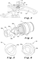
figure 1 est une vue en coupe de l'organe de commande selon l'invention, la couronne dudit organe de commande étant en position non enfoncée et neutre ; - la
figure 2 est une vue isométrique de l'organe de commande selon l'invention ; - la
figure 3 est une vue schématisée d'une tige de commande susceptible d'être solidarisée à l'organe de commande de la présente invention, agencé pour commander une fonction Remise à Zéro ou Flyback d'un mécanisme de chronographe et une fonction de correction du mois d'un mécanisme indicateur des mois, d'une pièce d'horlogerie, l'organe de commande étant dans sa position de non enfoncée et neutre ;
- la
figure 4 est une vue isométrique du dispositif de retour automatique selon l'invention ; - la
figure 5 est une vue isométrique de la première came femelle de lafigure 4 ; - la
figure 6 est une vue isométrique de la deuxième came mâle de lafigure 4 ; - les
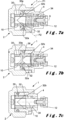
figures 7a, 7b et 7c sont des vues en coupe représentant l'organe de commande avec la couronne respectivement dans sa position non enfoncée neutre, dans sa position angulaire d'actionnement instable et non enfoncée, et dans sa position enfoncée.
- there
figure 1 is a sectional view of the control member according to the invention, the crown of said control member being in the non-pressed and neutral position; - there
figure 2 is an isometric view of the control member according to the invention; - there
Figure 3 is a schematic view of a control rod capable of being secured to the control member of the present invention, arranged to control a Reset or Flyback function of a chronograph mechanism and a month correction function 'a mechanism indicating the months, a timepiece, the control member being in its non-pressed and neutral position;
- there
figure 4 is an isometric view of the automatic return device according to the invention; - there
figure 5 is an isometric view of the first female cam of thefigure 4 ; - there
Figure 6 is an isometric view of the second male cam of thefigure 4 ; - THE
figures 7a, 7b and 7c are sectional views showing the control member with the crown respectively in its neutral non-pressed position, in its unstable and non-pressed angular actuation position, and in its depressed position.
En référence aux
La couronne 2 est agencée pour occuper une position non enfoncée ou de repos représentée sur la
Avantageusement, la couronne 2 est agencée pour être mobile en rotation axiale dans un sens entre la position angulaire neutre, stable, définissant une position angulaire stable, de préférence centrale, et une première position angulaire d'actionnement instable, et pour être mobile en rotation axiale dans l'autre sens entre ladite position neutre et une deuxième position angulaire d'actionnement instable. Lorsque la première fonction est une fonction de correction d'un mécanisme, la première position angulaire d'actionnement instable correspond typiquement à une première position de correction du mécanisme, et la deuxième position angulaire d'actionnement instable correspond typiquement à une deuxième position de correction du mécanisme.Advantageously, the
Avantageusement, la couronne 2 est mobile en rotation axiale sur un angle inférieur à 360°, de préférence inférieur à 180°, et plus préférentiellement inférieur ou égal à 70° dans chaque sens de rotation.Advantageously, the
De plus, dans un mode de réalisation préféré, la couronne 2 est également agencée pour, en réponse à une pression sur ladite couronne 2, être mobile en translation axiale entre sa position non enfoncée ou de repos représentée sur la
La couronne 2 comporte une tête 6, une jupe axiale 8 solidaire de la tête 6 et une tige centrale 10 connectée à la tête 6 ou solidaire de cette dernière. L'ensemble formé par la couronne 2 et la tige centrale 10 présente une symétrie de révolution autour de l'axe A. La tige centrale 10 est montée mobile en rotation axiale, et de préférence en translation axiale, selon ledit axe longitudinal A dans le tube de guidage 4. La tête 6 et la jupe 8 sont montées mobiles autour du tube de guidage 4 en rotation, et de préférence en translation, selon l'axe A.The
La tige centrale 10 est destinée à être solidarisée à la tige de commande 3 au moyen par exemple d'un carré d'entrainement femelle 12 fixé à l'extrémité libre de la tige centrale 10 par vissage et dans lequel est destiné à s'emboiter un carré mâle 14 (cf.
Ainsi, la couronne 2, avec la tige centrale 10, et la tige de commande 3 une fois montée sur la tige centrale 10, sont toujours solidaires en déplacement (en rotation et en translation). Elles peuvent être tournées autour de l'axe A à l'instar d'une tige de commande et, dans le mode de réalisation préféré dans lequel la couronne 2 fonctionne également à l'instar d'un poussoir, elles peuvent être déplacées en translation axiale selon l'axe A dans une position enfoncée par un utilisateur afin de commander deux fonctions différentes de la pièce d'horlogerie, et plus précisément des fonctions de deux complications différentes, comme cela sera décrit plus en détails ci-après.Thus, the
Plus particulièrement, la pièce d'horlogerie comprend une première complication, la première fonction étant liée à cette première complication et pouvant être par exemple une fonction de correction rapide d'un mécanisme, la ou les position(s) angulaire(s) d'actionnement instable(s) correspondant à une ou des position(s) de correction du mécanisme. Par exemple, la pièce d'horlogerie peut comprendre un mécanisme indicateur du mois ou un mécanisme de chronographe, la première fonction étant une fonction de correction du mois, respectivement au moins une fonction du chronographe telles que la fonction START/STOP, la fonction de Remise à Zéro ou Flyback, de préférence la fonction de Remise à Zéro ou Flyback. Il est bien évident que toute autre complication qui pourrait être corrigée par une rotation rapide de la couronne 2, telle qu'une lune, peut être utilisée.More particularly, the timepiece comprises a first complication, the first function being linked to this first complication and being able to be for example a rapid correction function of a mechanism, the angular position(s) of unstable actuation(s) corresponding to one or more correction position(s) of the mechanism. For example, the timepiece may comprise a month indicator mechanism or a chronograph mechanism, the first function being a month correction function, respectively at least one chronograph function such as the START/STOP function, the Reset or Flyback, preferably the Reset or Flyback function. It is obvious that any other complication which could be corrected by a rapid rotation of the
La pièce d'horlogerie peut comprendre une deuxième complication, comme un mécanisme de chronographe, et la deuxième fonction est l'une des fonctions chronographe telles que la fonction START/STOP, la fonction de Remise à Zéro ou Flyback. Il est bien évident que toute autre complication qui pourrait être corrigée par une pression sur la couronne 2, telle que le jour ou la semaine, peut être utilisée.The timepiece may include a second complication, such as a chronograph mechanism, and the second function is one of the chronograph functions such as the START/STOP function, the Reset or Flyback function. It is quite obvious that any other complication which could be corrected by pressing on
Par exemple, la pièce d'horlogerie peut comprendre un mécanisme indicateur du mois et un mécanisme de chronographe, la première fonction étant une fonction de correction du mois, la deuxième fonction étant l'une des fonctions chronographe, de préférence la fonction de Remise à Zéro ou Flyback.For example, the timepiece may comprise a month indicator mechanism and a chronograph mechanism, the first function being a month correction function, the second function being one of the chronograph functions, preferably the reset function. Zero or Flyback.
Toute autre complication adéquate peut être utilisée.Any other suitable complication may be used.
Afin de pouvoir commander une première fonction via la tige de commande 3 par une rotation de la couronne 2, et de préférence une deuxième fonction via ladite tige de commande 3 par une pression sur la couronne 2, la tige de commande 3 est agencée pour être solidaire en rotation d'un premier dispositif d'actionnement de la première fonction, et pour, de préférence, être agencée pour coopérer avec un deuxième dispositif d'actionnement de la deuxième fonction lors du déplacement de la couronne 2 dans sa position enfoncée, tout en étant libre en translation axiale par rapport au premier dispositif d'actionnement.In order to be able to control a first function via the
Des détails sur une telle tige de commande 3 sont donnés dans la demande
D'une manière avantageuse, la tige de commande 3 présente également une gorge 26 et le deuxième dispositif d'actionnement comprend une tirette 28 montée pivotante sur un élément du bâti, engagée dans ladite gorge 26 et agencée pour actionner la deuxième fonction, par exemple la fonction Remise à Zéro d'un mécanisme de chronographe, lors d'une pression sur la couronne 2 entrainant une translation axiale de la tige de commande 3.Advantageously, the
Dans l'exemple représenté, lors d'une rotation rapide de la couronne 2 et donc de la tige de commande 3, le ressort 22 et la bascule de centrage 20 agissent sur le cœur 24. Dès que le couple transmis à la tige de commande 3 est relâché, le ressort 22 et la bascule de centrage 20 agissent sur les parois du cœur 24 pour le repositionner, avec notamment la tige de commande 3, et donc repositionner la couronne 2 dans sa position angulaire neutre centrale, stable.In the example shown, during rapid rotation of the
Conformément à l'invention, l'organe de commande 1 comprend son propre dispositif de retour automatique de la couronne 2 d'une de ses positions d'actionnement instables à sa position neutre stable.In accordance with the invention, the
Dans l'exemple représenté, le dispositif de retour automatique à la position stable intégré à l'organe de commande selon l'invention est utilisé pour renforcer le dispositif de retour automatique de la tige de commande 3. Mais il est bien évident que le dispositif de retour automatique à la position stable intégré à l'organe de commande selon l'invention peut être prévu seul, sans aucun dispositif de rappel ou équivalent prévu notamment sur la tige de commande.In the example shown, the automatic return device to the stable position integrated into the control member according to the invention is used to reinforce the automatic return device of the
Ledit dispositif de retour automatique de l'organe de commande 1 comprend une première came 30 tubulaire, montée solidaire autour de la tige centrale 10 du côté de la base 10a de ladite tige centrale 10 solidaire de la tête 6 de la couronne 2, de sorte que la première came 30 tourne avec la tige centrale 10 selon l'axe A lorsque la couronne 2, dans sa position non enfoncée, est tournée dans un sens ou dans l'autre. Dans le mode de réalisation préféré dans lequel la couronne 2 fonctionne également à l'instar d'un poussoir, la première came 30 est également déplacée en translation selon l'axe A avec la tige centrale 10 lorsqu'une pression est exercée sur la couronne 2.Said automatic return device of the
Le dispositif de retour automatique comprend également une deuxième came tubulaire 32 logée dans le tube de guidage 4, montée libre en translation axiale sur la tige centrale 10 et agencée pour pouvoir essentiellement, voire uniquement, coulisser axialement dans ledit tube de guidage 4 en étant guidée principalement en translation axiale dans ledit tube de guidage 4, sa rotation par rapport audit tube de guidage 4 étant minime, voire impossible, et pour coopérer avec un ressort 34 prévu dans le tube de guidage 4, enroulé autour de la tige centrale 10 entre le fond du tube de guidage 4 et la deuxième came 32.The automatic return device also comprises a second
En référence plus particulièrement aux
Avantageusement, les surfaces de travail 30a, 32a sont en contact direct l'une avec l'autre, de préférence sur l'ensemble du profil de came lorsque la couronne 2 est dans sa position neutre.Advantageously, the working
Avantageusement, la première came 30 est une came femelle et la deuxième came 32 est une came mâle de sorte que la deuxième came mâle 32 pénètre, et de préférence s'emboîte, dans la première came femelle 30 lorsqu'elles sont suffisamment rapprochées, la surface de travail 32a à l'extrémité de la deuxième came mâle 32, en vis-à-vis de la première came femelle 30, pouvant alors venir en prise avec la surface de travail 30a à l'extrémité de ladite première came femelle 30.Advantageously, the
De préférence, la surface de travail 30a de la première came femelle 30 présente un profil obtenu en coupant ladite première came 30 par au moins un plan incliné sur l'axe A d'un angle compris de préférence entre |30°| et |45°|, pour pouvoir obtenir par exemple un angle d'ouverture de la première came de 70° +/- 10°. La surface de travail 32a de la deuxième came mâle 32 présente de préférence un profil de forme complémentaire, de sorte que la surface de travail 32a de la deuxième came mâle 32 peut venir en prise avec la surface de travail 30a de la première came femelle 30.Preferably, the working
Selon un mode de réalisation préféré, les surfaces de travail 30a, 32a des première et seconde cames 30, 32 présentent un profil obtenu en coupant lesdites première et deuxième cames 30, 32 par deux plans P1 et P2 inclinés sur l'axe A et symétriques par rapport audit axe A, comme montré sur la
Ainsi, la première came 30 est de préférence une came femelle dont la surface de travail 30a présente un profil obtenu en coupant ladite première came 30 par deux plans P1, P2 inclinés sur l'axe A d'un angle compris de préférence entre 30° et 45° pour l'un, ici P1, et compris de préférence entre -45° et -30° pour l'autre, ici P2, lesdits plans P1 et P2 étant symétriques par rapport audit axe A. La deuxième came 32 est une came mâle dont la surface de travail présente un profil de forme complémentaire, de sorte que la surface de travail 32a de la deuxième came mâle 32 peut venir en prise avec la surface de travail 30a de la première came femelle 30.Thus, the
De préférence, la première came 30 présente, à son extrémité en vis-à-vis de la deuxième came 32, une surface de travail 30a dont le profil comprend par exemple deux plans inclinés sur l'axe A et symétriques, conférant à cette première came 30 une forme cylindrique entaillée en V. La première came 30 présente, à son extrémité opposée à la surface de travail 30a, une section 30b circulaire, perpendiculaire à l'axe A, venant en appui sur la base 10a de la tige centrale 10.Preferably, the
La deuxième came 32 présente, à son extrémité en vis-à-vis de la première came 30, une surface de travail 32a dont le profil comprend par exemple deux plans inclinés sur l'axe A et symétriques, conférant à cette deuxième came 32 une forme complémentaire à celle de la première came 30 donnée par la surface de travail 30a. La deuxième came 32 présente, à son extrémité opposée à la surface de travail 32a, une portée 32b agencée pour être logée dans le tube de guidage 4 et pour coopérer avec le ressort 34 prévu au fond du tube de guidage 4.The
La deuxième came 32 est agencée pour être logée coulissante dans le tube de guidage 4 en y étant bloquée en rotation.The
A cet effet, la paroi intérieure du tube de guidage 4 présente typiquement des cannelures 36 longitudinales représentées sur la
D'une manière avantageuse, dans le mode de réalisation préféré dans lequel la couronne 2 fonctionne également à l'instar d'un poussoir, le ressort 34 est également le ressort qui sert à ramener la couronne 2 de sa position enfoncée à sa position non enfoncée lorsque la pression exercée de l'extérieur de la carrure sur la couronne 2 cesse.Advantageously, in the preferred embodiment in which the
En effet, lorsqu'une pression est exercée sur la couronne 2, la première came 30 déplacée en translation selon l'axe A avec la tige centrale 10 entraine, par coopération des surfaces de travail 30a, 32a qui de préférence restent en contact sur l'ensemble du profil de came, une translation axiale de la deuxième came 32 dans le tube de guidage 4 comprimant le ressort 34. Une translation axiale de la deuxième came 32 ramenée ou poussée par le ressort 34 lorsque la pression exercée de l'extérieur sur la couronne 2 cesse, entraine, par coopération des surfaces de travail 30a, 32a restées ainsi en contact, une translation axiale de la première came 30, et donc de la tige centrale 10, qui ramène et replace la couronne 2 dans sa position non enfoncée.Indeed, when pressure is exerted on the
En référence aux
Lorsque la couronne 2 est dans sa position non enfoncée, et neutre, les première et deuxième cames 30 et 32 sont positionnées sur la tige centrale 10 emboitées l'une dans l'autre de sorte que leurs surfaces de travail 30a, 32a sont étant au contact direct l'une de l'autre, typiquement sur l'ensemble du profil de came, comme le montre la
Dans cette position, lorsque la couronne 2 est tournée dans un sens ou dans l'autre, dans l'une de ses positions angulaires d'actionnement instables, d'un angle de ± 65° par exemple, pour réaliser une correction rapide du mois ±1, par exemple, la rotation axiale de la couronne 2 entraine la rotation axiale de la première came 30 solidaire de la tige centrale 10, de sorte que la surface de travail 30a de la première came 30 pousse la surface de travail 32a de la deuxième came 32, qui bloquée ou essentiellement bloquée en rotation dans le tube de guidage 4, s'éloigne de la première came 30 en coulissant le long de la tige centrale 10 en direction du fond du tube de guidage 4, la portée 32b de la deuxième came 32 comprimant le ressort 34 dans le fond du tube de guidage 4, comme représenté sur la
En parallèle, la tige centrale 10, actionnée en rotation par la couronne 2, a entrainé la tige de commande 3 en rotation via les carrés 12 et 14, de manière à effectuer la correction rapide demandée dans un sens ou dans l'autre selon le sens de rotation de la couronne 2.In parallel, the
Lorsque la correction rapide est terminée et que l'utilisateur a relâché la couronne 2, le couple transmis à la tige centrale 10 pour entrainer sa rotation dans la position d'actionnement instable cesse. La deuxième came 32 n'étant plus contrainte par la première came 30 est ramenée par le ressort 34 en coulissant le long de la tige centrale 10 en direction de la première came 30. Ainsi, la surface de travail 32a de la deuxième came 32, en prise avec la surface de travail 30a de la première came 30, entraine la rotation de cette dernière dans le sens inverse, et donc la tige centrale 10, jusqu'à ce que les première et deuxième cames 30, 32 s'emboitent de nouveau. La rotation de la tige centrale 10 dans le sens inverse a ramené la couronne 2 dans sa position neutre, comme représenté sur la
Dans le mode de réalisation préféré dans lequel la couronne 2 fonctionne également à l'instar d'un poussoir, lorsque la couronne 2 est dans sa position angulaire stable, comme représenté sur la
Lors de son déplacement axial suite à une pression sur la couronne 2, la tige centrale 10 déplace avec elle en translation axiale la première came 30, qui, en restant emboitée avec la deuxième came 32 bloquée ou essentiellement bloquée en rotation dans le tube de guidage 4, la pousse en la faisant essentiellement voire uniquement coulisser dans le tube de guidage 4, la portée 32b de la deuxième came 32 comprimant le ressort 34 dans le fond du tube de guidage 4, comme représenté sur la
En parallèle, la tige centrale 10 en translation axiale a déplacé la tige de commande 3 également en translation axiale via les carrés 12 et 14, de manière à actionner la deuxième fonction, par exemple la remise à zéro de chronographe. Après relâchement de la pression sur la couronne 2 et donc sur la tige centrale 10, la deuxième came 32 poussée par le ressort 34 coulisse dans le tube de guidage vers l'extérieur en poussant elle-même sur la première came 30, et donc sur la tige centrale 10, de sorte que la tige centrale 10 et la couronne 2 reprennent la position non enfoncée représentée sur la
La pièce d'horlogerie peut comprendre un ou plusieurs organes de commande de l'invention, agencés pour actionner des premières et deuxièmes fonctions différentes, notamment des fonctions de plusieurs complications.The timepiece may comprise one or more control members of the invention, arranged to operate different first and second functions, in particular functions of several complications.
L'invention permet de commander au moins une fonction d'un mouvement horloger par rotation d'un organe de commande à l'instar d'une tige de commande rapide, garantissant un retour automatique à la position neutre, une fois la fonction actionnée.The invention makes it possible to control at least one function of a watch movement by rotation of a control member like a rapid control rod, guaranteeing an automatic return to the neutral position, once the function has been activated.
De plus, l'invention permet également avantageusement de commander deux fonctions différentes, notamment des fonctions de différentes complications, indépendantes l'une de l'autre, au moyen d'un organe de commande unique, l'une des fonctions étant commandée par ledit organe de commande à l'instar d'un poussoir et l'autre des fonctions étant commandée par ledit organe de commande à l'instar d'une tige de commande rapide, le retour automatique à la position neutre, une fois la fonction actionnée étant fiable et donc garanti.In addition, the invention also advantageously makes it possible to control two different functions, in particular functions of different complications, independent of each other, by means of a single control member, one of the functions being controlled by said control member like a pusher and the other of the functions being controlled by said control member like a rapid control rod, the automatic return to the neutral position, once the function activated being reliable and therefore guaranteed.
L'organe de commande unique combinant commande par rotation et commande par pression est un mode de réalisation préféré de l'invention, mais il est bien évident que l'organe de commande de l'invention peut être utilisé seulement avec la commande par rotation, sans fonction poussoir.The single control member combining rotation control and pressure control is a preferred embodiment of the invention, but it is obvious that the control member of the invention can be used only with rotation control, without push function.
Claims (15)
Priority Applications (2)
| Application Number | Priority Date | Filing Date | Title |
|---|---|---|---|
| EP22169142.1A EP4266130A1 (en) | 2022-04-21 | 2022-04-21 | Control member of at least one first function of a timepiece movement |
| PCT/EP2023/059902 WO2023202977A1 (en) | 2022-04-21 | 2023-04-17 | Member for controlling at least one function of a timepiece movement |
Applications Claiming Priority (1)
| Application Number | Priority Date | Filing Date | Title |
|---|---|---|---|
| EP22169142.1A EP4266130A1 (en) | 2022-04-21 | 2022-04-21 | Control member of at least one first function of a timepiece movement |
Publications (1)
| Publication Number | Publication Date |
|---|---|
| EP4266130A1 true EP4266130A1 (en) | 2023-10-25 |
Family
ID=81346544
Family Applications (1)
| Application Number | Title | Priority Date | Filing Date |
|---|---|---|---|
| EP22169142.1A Pending EP4266130A1 (en) | 2022-04-21 | 2022-04-21 | Control member of at least one first function of a timepiece movement |
Country Status (2)
| Country | Link |
|---|---|
| EP (1) | EP4266130A1 (en) |
| WO (1) | WO2023202977A1 (en) |
Citations (3)
| Publication number | Priority date | Publication date | Assignee | Title |
|---|---|---|---|---|
| US7255473B2 (en) * | 2005-01-17 | 2007-08-14 | Seiko Instruments Inc. | Portable timepiece |
| CH703455A1 (en) * | 2010-07-17 | 2012-01-31 | Pibor Iso S A | Crown i.e. winding crown, for use on watch case, has coupling units securing wheel and piston when head occupies stable translation position to modify function of timepiece movement and slide wheel inside tube |
| JP2017032286A (en) * | 2015-07-29 | 2017-02-09 | カシオ計算機株式会社 | Rotation operation device and watch |
Family Cites Families (2)
| Publication number | Priority date | Publication date | Assignee | Title |
|---|---|---|---|---|
| JP2015230270A (en) * | 2014-06-06 | 2015-12-21 | カシオ計算機株式会社 | Push button structure and watch |
| CH718356A1 (en) | 2021-02-16 | 2022-08-31 | Mft Dhorlogerie Audemars Piguet Sa | Control device for several functions of a watch movement. |
-
2022
- 2022-04-21 EP EP22169142.1A patent/EP4266130A1/en active Pending
-
2023
- 2023-04-17 WO PCT/EP2023/059902 patent/WO2023202977A1/en unknown
Patent Citations (3)
| Publication number | Priority date | Publication date | Assignee | Title |
|---|---|---|---|---|
| US7255473B2 (en) * | 2005-01-17 | 2007-08-14 | Seiko Instruments Inc. | Portable timepiece |
| CH703455A1 (en) * | 2010-07-17 | 2012-01-31 | Pibor Iso S A | Crown i.e. winding crown, for use on watch case, has coupling units securing wheel and piston when head occupies stable translation position to modify function of timepiece movement and slide wheel inside tube |
| JP2017032286A (en) * | 2015-07-29 | 2017-02-09 | カシオ計算機株式会社 | Rotation operation device and watch |
Also Published As
| Publication number | Publication date |
|---|---|
| WO2023202977A1 (en) | 2023-10-26 |
Similar Documents
| Publication | Publication Date | Title |
|---|---|---|
| CH685901B5 (en) | Crown-button timepiece. | |
| EP3253615B1 (en) | Releasable hinge assembly for a motor vehicle seat | |
| EP4266130A1 (en) | Control member of at least one first function of a timepiece movement | |
| EP1406132A1 (en) | Coupling mechanism for a chronographe | |
| EP2124112A1 (en) | Timepiece mechanism and module comprising such a mechanism | |
| EP4295198A1 (en) | Member for controlling a plurality of functions of a timepiece movement | |
| EP2141554A2 (en) | Push-button | |
| CH691088A5 (en) | mechanism at the time of a watch with perpetual calendar movement. | |
| CA2512218C (en) | Improvement to mechanized dental instruments, including endodontic instruments and contra-angle handpiece | |
| EP3002643B1 (en) | Chronograph mechanism with column wheel | |
| FR2931137A1 (en) | DEVICE FOR DISPENSING FLUID PRODUCT | |
| EP1960848B1 (en) | Timepiece hammer | |
| EP1710635A1 (en) | Command device for a timepiece and a watch provided with such a device | |
| FR2995412A1 (en) | Crown assembly for watch, has control rod that is controlled and immobilized in blocking position and releasing position of crown by manual pressure on push-button via commutation part interposed between central push button and crown | |
| CH708338A2 (en) | corrective mechanism step by step. | |
| CH706893B1 (en) | Set of telescopic wreath with erasing effect in the case of a watch. | |
| CH703622B1 (en) | Push trigger threshold for a timepiece. | |
| EP2339414A1 (en) | Chronograph with single push button | |
| CA2542879A1 (en) | Mechanical pencil | |
| CH702429A2 (en) | Mono-button chronograph for timepiece, has inclined surface that is arranged such that jumper pivots shuttle from intermediate instable angular position to stable angular position when button is released | |
| EP4279997A1 (en) | Member for controlling at least one function of a timepiece movement | |
| EP2565726B1 (en) | Command device for timepieces | |
| FR3113744A1 (en) | Control device with interchangeable crown for a timepiece | |
| EP4092490A1 (en) | Device for controlling a timepiece movement with touch return and timepiece, in particular a watch, including such a device | |
| EP3910424A1 (en) | Control device with lock and push button for a timepiece |
Legal Events
| Date | Code | Title | Description |
|---|---|---|---|
| STAA | Information on the status of an ep patent application or granted ep patent |
Free format text: STATUS: THE APPLICATION HAS BEEN PUBLISHED |
|
| PUAI | Public reference made under article 153(3) epc to a published international application that has entered the european phase |
Free format text: ORIGINAL CODE: 0009012 |
|
| AK | Designated contracting states |
Kind code of ref document: A1 Designated state(s): AL AT BE BG CH CY CZ DE DK EE ES FI FR GB GR HR HU IE IS IT LI LT LU LV MC MK MT NL NO PL PT RO RS SE SI SK SM TR |
|
| P01 | Opt-out of the competence of the unified patent court (upc) registered |
Effective date: 20231107 |