EP0655603A1 - Munition mit Geschossen die mittels Seilen miteinander verbunden sind - Google Patents
Munition mit Geschossen die mittels Seilen miteinander verbunden sind Download PDFInfo
- Publication number
- EP0655603A1 EP0655603A1 EP94116574A EP94116574A EP0655603A1 EP 0655603 A1 EP0655603 A1 EP 0655603A1 EP 94116574 A EP94116574 A EP 94116574A EP 94116574 A EP94116574 A EP 94116574A EP 0655603 A1 EP0655603 A1 EP 0655603A1
- Authority
- EP
- European Patent Office
- Prior art keywords
- projectile
- propellant
- illustrates
- balls
- projectiles
- Prior art date
- Legal status (The legal status is an assumption and is not a legal conclusion. Google has not performed a legal analysis and makes no representation as to the accuracy of the status listed.)
- Granted
Links
Images


Classifications
-
- F—MECHANICAL ENGINEERING; LIGHTING; HEATING; WEAPONS; BLASTING
- F41—WEAPONS
- F41H—ARMOUR; ARMOURED TURRETS; ARMOURED OR ARMED VEHICLES; MEANS OF ATTACK OR DEFENCE, e.g. CAMOUFLAGE, IN GENERAL
- F41H13/00—Means of attack or defence not otherwise provided for
- F41H13/0006—Ballistically deployed systems for restraining persons or animals, e.g. ballistically deployed nets
-
- F—MECHANICAL ENGINEERING; LIGHTING; HEATING; WEAPONS; BLASTING
- F42—AMMUNITION; BLASTING
- F42B—EXPLOSIVE CHARGES, e.g. FOR BLASTING, FIREWORKS, AMMUNITION
- F42B12/00—Projectiles, missiles or mines characterised by the warhead, the intended effect, or the material
- F42B12/02—Projectiles, missiles or mines characterised by the warhead, the intended effect, or the material characterised by the warhead or the intended effect
- F42B12/36—Projectiles, missiles or mines characterised by the warhead, the intended effect, or the material characterised by the warhead or the intended effect for dispensing materials; for producing chemical or physical reaction; for signalling ; for transmitting information
- F42B12/56—Projectiles, missiles or mines characterised by the warhead, the intended effect, or the material characterised by the warhead or the intended effect for dispensing materials; for producing chemical or physical reaction; for signalling ; for transmitting information for dispensing discrete solid bodies
- F42B12/58—Cluster or cargo ammunition, i.e. projectiles containing one or more submissiles
- F42B12/66—Chain-shot, i.e. the submissiles being interconnected by chains or the like
Definitions
- the present invention relates to a device for immobilizing moving targets such as animals or men, and more particularly a device whose cartridges can be used in conventional weapons.
- the main problem inherent in neutralizing or capturing a living being lies in immobilizing the subject without hurting it.
- cartridges for firearms using bullets made of flexible material such as rubber for example This type of ammunition can neutralize an animal or a human being, but has the disadvantage of causing injuries, sometimes serious depending on the point of impact of the bullet.
- the object of the present invention is to obviate the aforementioned drawbacks by providing a device intended to be incorporated into a standard cartridge, not causing damage to the subject against which it is used while guaranteeing effective immobilization.
- the device is distinguished by the characteristics listed in claim 1.
- the capture device comprises in its different embodiments, a propellant and a projectile.
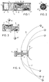
- Figure 1 illustrates the device in the form of a cartridge 1 of the type used in hunting weapons for example.
- the primer 2 used for firing as well as the socket 3 filled with powder 4 and wad 5 allowing the cartridge to be closed as in conventional ammunition.
- These various elements constitute the propellant part of the device.
- the projectile which is in the form of a cylindrical body 6 in which is housed a delayed explosive charge 7.
- a channel 8 is formed in the center of the cylindrical body 6. This channel 8 extends over practically the entire length of the body 6 and is in contact with the explosive charge 7 at one of its ends. Housing 9.9 'is provided in the body 6.
- housing 9.9' are intended to receive balls 10.10 'connected to flexible links 12.12' fixed in the bottom of the housing 9.9 '.
- the 10.10 'balls can be made of steel or hard plastic.
- plastic or steel wires are preferably used.
- the bottom of the housing 9,9' has at the point where the channels 11,11 'open, a hemispherical recess slightly smaller than the diameter of the balls 10,10' so that the balls 10,10 'close the channels 11,11' in the rest position.
- the flexible links 12, 12 ' are wound around the balls in the housings 9, 9'.
- Figure 2 illustrates in section the device.
- FIG. 3 illustrates the projectile in flight after its expulsion from the shell 3 following the explosion of the powder charge 4.
- the explosion expels the projectile out of the weapon and initiates the explosive charge 7 contained in the projectile.
- This delay charge 7 will, depending on its characteristics, explode after a variable flight time.
- the latency time of the explosive charge 7 will therefore be adjusted as a function of the proximity or the distance of the targets.
- the explosion of the charge 7 creates a significant overpressure in the channel 8, thereby causing the deployment of the balls 10, 10 ′.
- Figure 4 illustrates the projectile upon impact with the objective.
- the flexible links 12,12 ′ are then fully deployed and the balls will be wound by inertia around the objective 13 thus causing it to be surrounded by the links 12,12 ′ and thereby immobilizing the subject.
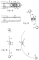
- FIG. 5 illustrates a second embodiment of the capture device which comprises a projectile of the same type as that described in the first embodiment illustrated in FIGS. 1 to 4.
- the propellant in this embodiment is a propellant rocket 14 which can be fired using a pistol or rifle launching rocket 15.
- the rocket 14 contains a propellant charge 16.
- a retaining wire 17 is fixed to the rifle launching rocket 15 to one of its ends and wound around the propellant rocket 14. The other end of this retaining wire is fixed to the projectile 18 carried by the rocket 14.
- the projectile 18 is identical to that described in the first embodiment in Figures 1 to 4 except for an annular cut 19 allowing it to fit into the end of the rocket 14.
- Figure 7 illustrates the rocket 14 shortly after firing, we see the retaining wire 17 in the process of unwinding.
- the projectile 18 separates from the propellant rocket 14 and the balls 21, 21 ′ are expelled from their housings under the effect of the overpressure created in the channel 22.
- the objective 24 is surrounded by the lead wires either at the time of the impact of the projectile with the latter or during a traction on the retaining wire caused by the complete unwinding of the retaining wire 17.
- the objective once immobilized by the lead wires, can be brought back to the shooter by means of the retaining wire 17 secured to the propellant rifle.
- the retaining wire 17 can be used to trigger the explosion of the explosive charge 20 contained in the projectile. As soon as the retaining wire is fully unwound, the tension of the wire on a percussion mechanism (not shown) triggers the immediate explosion of the load 20.
- FIG. 10 illustrates a third embodiment of the capture device.
- the projectile 25 is mounted inside a launch tube 26 mounted on a pistol or a propellant rifle 27.
- the projectile 25 is composed a hollow cylindrical body 28 in which is wound a retaining wire 29.
- One end of this retaining wire 29 is fixed in the launch tube and the other in the bottom of the body 28.
- the body 28 is extended by a second cylindrical body 30 of smaller diameter.
- the end of this cylindrical body 30 is conical and balls 32,32 ', 32''are held by the base of this cone and the edges of the launch tube 26.
- the balls 32,32'32''are each connected to a wire which comes to wrap around the cylindrical body 30. The end of these wires is fixed to the body 28.
- FIG. 13 illustrates the encirclement of the objective by the balls 32, 32 ′, 32 ′′ either at the moment of the impact of the projectile with the objective or during a tension appearing on the retaining wire 29 when this the latter is completely unrolled.
- FIG 14 illustrates a variant of the projectile in the launch tube.
- the projectile consists of two balls 35,35 ′, the diameter of which is slightly less than the diameter of the launching tube 39. These two balls are located on either side of a cylindrical body. This body has a central part 36 whose diameter is substantially equal to that of the balls 35, 35 ′. On each side of this central part, there is a cylinder with a smaller diameter 37.37 'bevelled at its free end. The balls bear against the flat face of this bevel.
- the balls 35, 35 ′ are connected to the central part 36 of the cylindrical body by the flexible links 38,38 'which are wound around the cylinders 37,37'.
- FIG. 15 illustrates the projectile in flight after its expulsion from the launch tube, at this moment the balls 25, 25 ′ deploy on either side of the body.
- Figure 16 shows the projectile in flight and fully deployed.
- Figure 17 illustrates the projectile at the time of impact which causes the surrounding of the target by the links 38,38 'terminated by the balls 35,35'.
- FIG. 18 illustrates a fifth embodiment of the device which comprises a propellant in the form of a socket 40 and a projectile, these two elements forming a cartridge of the type used in hunting weapons for example.
- a socket 40 containing powder 41.
- a hollow cylindrical envelope 42 containing a spring 43.
- the projectile itself is in the form of an inverted T 44.
- the part 44 is slidably mounted inside the casing 42 and can move longitudinally against the action of a spring 43 fixed in the bottom of the casing 42.
- the part 44 comprises two balls 45, 45 'bearing against the base of the T. These balls are connected by flexible links 46,46 'which are fixed against the head of the T.
- FIG. 19 illustrates the projectile after firing, the part 44 under the effect of the thrust will compress the spring 43.
- the spring 43 will restore its energy and expel the part 44 which will separate from the envelope 42 as well as it is illustrated in figure 20.
- the balls under the effect of the rotation of the projectile will deploy until complete tension of the links 46,46 '.
- Figure 21 finally shows the projectile at the time of impact with the objective.
- the balls connected by means of the links described in the different embodiments can be replaced by weights provided with a hook or an adherent coating such as velcro for example.
- FIGS 22 and 23 illustrate a sixth embodiment of the capture device.
- the projectile 47 is composed of two symmetrical parts each comprising a projectile head 47 ′, 47 ′′ attached to a base 48 ′, 48 ′′. These bases 48 ', 48''are extended by a semi-cylindrical rod intended to be introduced into the end of the barrel 49 of a firearm such as a revolver or a pistol. The propulsion of the projectile is ensured by a blank cartridge for example.
- the two projectiles 47 ', 47'' are connected together by a flexible link 50. One end of this link 50 is fixed in the base 48' while the other end of the link 50 is secured to the base 48 ''.
- the link 50 is wound on top of the projectiles 47 ', 47''without surrounding them as is apparent from Figure 22.
- An envelope 51 generally made of cardboard or plastic, surrounds and maintains side by side the two half projectiles 47 ', 48', 47 '', 48 ''.
- This envelope has an opening at its end opposite to the barrel of the weapon which facilitates its separation during the departure of the shot.
- the projectile heads 47 ', 47'' are provided respectively with external fins 52', 52 '' and internal fins 53 ', 53''which favor the separation of the two half projectiles 47 ', 47'',48', 48 '' in flight.
- the envelope 51 tears and falls back in front of the barrel and the projectiles 47 ', 47'',48', 48 '' tend to move away from each other in opposite directions in a horizontal plane until the link 50 which connects them is fully tensioned.
- the central part of the link 50 will touch the subject and by inertia the half projectiles 47 ', 48' and 47 '', 48 '' will surround and immobilize the subject.
- peaks or hooks 54 fixed in the bases 48 ', 48''of the projectiles. These hooks 54 have the function of hanging on the clothing or in the skin of the captured subject, thus preventing easy release.
- Marks 55 are made by any suitable means on the semi-cylindrical rods extending the bases 48 ', 48''. These marks 55 serve as a reference and allow to adjust the introduction of the half rods in the barrel. It is thus possible by introducing the rod of the projectile 47 more or less deeply into the barrel 49 of the weapon to adjust the shooting distance.
- FIG. 24 is an end view of the two half projectiles 47 ′, 47 ′′ without their protective cover 51.
- FIG. 25 illustrates a variant of the projectile illustrated in FIG. 22.
- This projectile also consists of two half-projectiles each comprising a head 47 ', 47''secured to a base 48', 48 ''.
- a channel 56 is formed in the center of the rod consisting of the two half-rods extending the bases 48', 48 ''.
- This channel 56 opens at one of its ends in the barrel 49 of the weapon and at its other end in a recess 57 located at the junction point of heads 47 ', 47''and bases 48', 48 ''.
- This recess 57 communicates with cavities 58 ', 58''formed in the projectile heads 47', 47 ''.
- a powder charge or a rocket fills the cavities 58 ', 58''of each half-projectile.
- Quick wicks 59 ', 59'' are in contact with the powder charges at one of their ends and open into the barrel 49 of the weapon through the channel 56.
- Circular orifices of small diameter 60 ', 60'' are provided in the bases 48', 48 '' of the half projectiles and allow the evacuation of the combustion gases of the charges located in the cavities 48 ', 48''.
- This variant offers the advantage of increasing the effect of encircling the subject during the impact which is caused not only because of the inertia of the half projectiles but also thanks to the thrust generated by the combustion of the charges of powder .
- Figure 26 illustrates a second variant of the projectile illustrated in Figure 22.
- the channel 46 communicates via passages 61 ', 61''with the cavities 58', 58 '' located in the heads 47 ' , 47 ''.
- the explosion of the propellant charge causes an overpressure in the cavities 58 ′, 58 ′′.
- the pressure thus created in the cavities causes a reaction effect when the gases escape through the orifices 60'60 '' increasing the inertia effect when the half projectiles are wound around the subject at the time of impact .
- the flexible links connecting the elements constituting the projectile may include attachment members.
- These organs have the function, after winding the projectile around the subject, to hang in the clothing or in the skin of the subject thereby increasing the difficulty of being released from the projectile.
- These organs may consist of hooks or hooks fixed by any suitable means and distributed along the flexible link.
- these members can be in the form of roughness such as that found on traditional barbed wire.
Landscapes
- Engineering & Computer Science (AREA)
- General Engineering & Computer Science (AREA)
- Radar, Positioning & Navigation (AREA)
- Remote Sensing (AREA)
- Chemical & Material Sciences (AREA)
- Combustion & Propulsion (AREA)
- Toys (AREA)
- Devices Affording Protection Of Roads Or Walls For Sound Insulation (AREA)
- Treatment Of Liquids With Adsorbents In General (AREA)
- Aiming, Guidance, Guns With A Light Source, Armor, Camouflage, And Targets (AREA)
- Telescopes (AREA)
- Surgical Instruments (AREA)
- Physical Deposition Of Substances That Are Components Of Semiconductor Devices (AREA)
- Eye Examination Apparatus (AREA)
Applications Claiming Priority (2)
| Application Number | Priority Date | Filing Date | Title |
|---|---|---|---|
| CH3287/93 | 1993-11-01 | ||
| CH03287/93A CH688946A5 (fr) | 1993-11-01 | 1993-11-01 | Dispositif de capture, notamment pour arme à feu. |
Publications (2)
| Publication Number | Publication Date |
|---|---|
| EP0655603A1 true EP0655603A1 (de) | 1995-05-31 |
| EP0655603B1 EP0655603B1 (de) | 1997-03-05 |
Family
ID=4252725
Family Applications (1)
| Application Number | Title | Priority Date | Filing Date |
|---|---|---|---|
| EP94116574A Expired - Lifetime EP0655603B1 (de) | 1993-11-01 | 1994-10-20 | Munition mit Geschossen die mittels Seilen miteinander verbunden sind |
Country Status (6)
| Country | Link |
|---|---|
| EP (1) | EP0655603B1 (de) |
| AT (1) | ATE149673T1 (de) |
| CH (1) | CH688946A5 (de) |
| DE (1) | DE69401901T2 (de) |
| IL (1) | IL111420A0 (de) |
| ZA (1) | ZA948456B (de) |
Cited By (17)
| Publication number | Priority date | Publication date | Assignee | Title |
|---|---|---|---|---|
| EP0841530A3 (de) * | 1996-11-07 | 1998-11-18 | Daimler-Benz Aerospace Aktiengesellschaft | Vorrichtung zum Aufspannen von Netzen |
| EP0872701A3 (de) * | 1997-04-19 | 1998-11-25 | LFK Lenkflugkörpersysteme GmbH | Fangnetz für Personen |
| EP0983480A2 (de) * | 1997-05-30 | 2000-03-08 | Foster Miller, Inc. | Ballistisch ausspreizbares rückhaltenetz |
| GB2386673A (en) * | 2002-03-21 | 2003-09-24 | Roke Manor Research | Target immobilisation device / bolas arrangement |
| WO2004088150A2 (fr) * | 2003-03-26 | 2004-10-14 | Eads Space Transportation Sa | Assemblage pour lanceur comprenant un dispositif de fixation susceptible d'isoler un equipement d'un environnement dynamique et/ou pyrotechnique |
| EP1583933A2 (de) * | 2002-08-29 | 2005-10-12 | Raytheon Company | Festgelegtesentfaltbares netz für hit-to-kill-fahrzeug |
| DE102005023484A1 (de) * | 2005-05-21 | 2006-11-23 | Diehl Bgt Defence Gmbh & Co. Kg | Wurfeinrichtung |
| US7441511B2 (en) | 2005-02-28 | 2008-10-28 | Foster-Miller, Inc. | Watercraft arresting system |
| US7866250B2 (en) | 2006-02-09 | 2011-01-11 | Foster-Miller, Inc. | Vehicle protection system |
| US7900548B2 (en) | 2006-02-09 | 2011-03-08 | Foster Miller, Inc. | Protection system including a net |
| US8011285B2 (en) | 2008-04-16 | 2011-09-06 | Foster-Miller, Inc. | Vehicle and structure shield |
| US8245620B2 (en) | 2008-04-16 | 2012-08-21 | QinetiQ North America, Inc. | Low breaking strength vehicle and structure shield net/frame arrangement |
| US8443709B2 (en) | 2008-04-16 | 2013-05-21 | QinetiQ North America, Inc. | Vehicle and structure shield hard point |
| US8615851B2 (en) | 2008-04-16 | 2013-12-31 | Foster-Miller, Inc. | Net patching devices |
| EP2635870A4 (de) * | 2010-11-02 | 2017-08-09 | Advanced Ballistic Concepts LLC | Geschoss zur verwendung mit einem büchsenlauf |
| ES2799373A1 (es) * | 2019-06-13 | 2020-12-16 | Ruiz Juan Antonio Zamora | Cartucho con red para escopeta |
| US11304413B2 (en) * | 2008-06-25 | 2022-04-19 | Brett E. Bunker | Pest control devices, methods, and apparatus |
Families Citing this family (10)
| Publication number | Priority date | Publication date | Assignee | Title |
|---|---|---|---|---|
| US20090320711A1 (en) | 2004-11-29 | 2009-12-31 | Lloyd Richard M | Munition |
| US20110079135A1 (en) | 2008-04-16 | 2011-04-07 | Farinella Michael D | Vehicle and structure shield net/frame arrangement |
| US8464627B2 (en) | 2008-04-16 | 2013-06-18 | QinetiQ North America, Inc. | Vehicle and structure shield with improved hard points |
| US8468927B2 (en) | 2008-04-16 | 2013-06-25 | QinetiQ North America, Inc. | Vehicle and structure shield with a cable frame |
| US8453552B2 (en) | 2008-04-16 | 2013-06-04 | QinetiQ North America, Inc. | Method of designing an RPG shield |
| US8607685B2 (en) | 2008-04-16 | 2013-12-17 | QinetiQ North America, Inc. | Load sharing hard point net |
| US8677882B2 (en) | 2010-09-08 | 2014-03-25 | QinetiQ North America, Inc. | Vehicle and structure shield with flexible frame |
| DE102012000893B4 (de) * | 2012-01-18 | 2014-12-24 | Bundesrepublik Deutschland, vertreten durch das Bundesministerium der Verteidigung, dieses vertreten durch das Bundesamt für Ausrüstung, Informationstechnik und Nutzung der Bundeswehr | Retardierend zerlegende Geschosshülle |
| US8813631B1 (en) | 2013-02-13 | 2014-08-26 | Foster-Miller, Inc. | Vehicle and structure film/hard point shield |
| DE102017112769A1 (de) * | 2017-06-09 | 2018-12-13 | Droptec Gmbh | Abfangvorrichtung zum Abfangen von unbemannten Flugobjekten |
Citations (8)
| Publication number | Priority date | Publication date | Assignee | Title |
|---|---|---|---|---|
| FR491876A (fr) * | 1916-05-24 | 1919-06-20 | Amedeo Porcile | Projectile pour le tir contre les aéroplanes, dirigeables et autres véhicules aériens |
| US1488182A (en) * | 1921-11-17 | 1924-03-25 | Gordon T Whelton | Ordnance projectile |
| FR805306A (fr) * | 1935-08-06 | 1936-11-17 | Procédé de protection contre avions | |
| FR918204A (fr) * | 1945-07-27 | 1947-02-03 | Ct D Etudes M B A | Appareil de lancement pour la mise en place de barrage anti-aérien |
| US4559737A (en) * | 1983-12-12 | 1985-12-24 | Washington Richard J | Snare device |
| US4664034A (en) * | 1985-04-23 | 1987-05-12 | Christian Dale W | Fettered shot |
| DE9214515U1 (de) * | 1992-10-27 | 1993-01-07 | Friebel, Otto, 8000 Muenchen, De | |
| DE9308186U1 (de) * | 1993-04-23 | 1993-09-02 | Bugiel Horst Georg Dipl Ing | Einrichtung zum vorübergehenden Außer-Gefecht-Setzen einer Person |
-
1993
- 1993-11-01 CH CH03287/93A patent/CH688946A5/fr not_active IP Right Cessation
-
1994
- 1994-10-20 EP EP94116574A patent/EP0655603B1/de not_active Expired - Lifetime
- 1994-10-20 AT AT94116574T patent/ATE149673T1/de not_active IP Right Cessation
- 1994-10-20 DE DE69401901T patent/DE69401901T2/de not_active Expired - Fee Related
- 1994-10-27 ZA ZA948456A patent/ZA948456B/xx unknown
- 1994-10-27 IL IL11142094A patent/IL111420A0/xx unknown
Patent Citations (8)
| Publication number | Priority date | Publication date | Assignee | Title |
|---|---|---|---|---|
| FR491876A (fr) * | 1916-05-24 | 1919-06-20 | Amedeo Porcile | Projectile pour le tir contre les aéroplanes, dirigeables et autres véhicules aériens |
| US1488182A (en) * | 1921-11-17 | 1924-03-25 | Gordon T Whelton | Ordnance projectile |
| FR805306A (fr) * | 1935-08-06 | 1936-11-17 | Procédé de protection contre avions | |
| FR918204A (fr) * | 1945-07-27 | 1947-02-03 | Ct D Etudes M B A | Appareil de lancement pour la mise en place de barrage anti-aérien |
| US4559737A (en) * | 1983-12-12 | 1985-12-24 | Washington Richard J | Snare device |
| US4664034A (en) * | 1985-04-23 | 1987-05-12 | Christian Dale W | Fettered shot |
| DE9214515U1 (de) * | 1992-10-27 | 1993-01-07 | Friebel, Otto, 8000 Muenchen, De | |
| DE9308186U1 (de) * | 1993-04-23 | 1993-09-02 | Bugiel Horst Georg Dipl Ing | Einrichtung zum vorübergehenden Außer-Gefecht-Setzen einer Person |
Cited By (26)
| Publication number | Priority date | Publication date | Assignee | Title |
|---|---|---|---|---|
| EP0841530A3 (de) * | 1996-11-07 | 1998-11-18 | Daimler-Benz Aerospace Aktiengesellschaft | Vorrichtung zum Aufspannen von Netzen |
| EP0872701A3 (de) * | 1997-04-19 | 1998-11-25 | LFK Lenkflugkörpersysteme GmbH | Fangnetz für Personen |
| EP0983480A2 (de) * | 1997-05-30 | 2000-03-08 | Foster Miller, Inc. | Ballistisch ausspreizbares rückhaltenetz |
| EP0983480A4 (de) * | 1997-05-30 | 2000-11-08 | Foster Miller Inc | Ballistisch ausspreizbares rückhaltenetz |
| GB2386673A (en) * | 2002-03-21 | 2003-09-24 | Roke Manor Research | Target immobilisation device / bolas arrangement |
| GB2386673B (en) * | 2002-03-21 | 2005-02-23 | Roke Manor Research | Target immobilisation device |
| US7415917B2 (en) | 2002-08-29 | 2008-08-26 | Raytheon Company | Fixed deployed net for hit-to-kill vehicle |
| EP1583933A2 (de) * | 2002-08-29 | 2005-10-12 | Raytheon Company | Festgelegtesentfaltbares netz für hit-to-kill-fahrzeug |
| EP1583933A4 (de) * | 2002-08-29 | 2006-04-05 | Raytheon Co | Festgelegtesentfaltbares netz für hit-to-kill-fahrzeug |
| WO2004088150A2 (fr) * | 2003-03-26 | 2004-10-14 | Eads Space Transportation Sa | Assemblage pour lanceur comprenant un dispositif de fixation susceptible d'isoler un equipement d'un environnement dynamique et/ou pyrotechnique |
| WO2004088150A3 (fr) * | 2003-03-26 | 2004-11-18 | Eads Space Transportation Sa | Assemblage pour lanceur comprenant un dispositif de fixation susceptible d'isoler un equipement d'un environnement dynamique et/ou pyrotechnique |
| US7441511B2 (en) | 2005-02-28 | 2008-10-28 | Foster-Miller, Inc. | Watercraft arresting system |
| DE102005023484A1 (de) * | 2005-05-21 | 2006-11-23 | Diehl Bgt Defence Gmbh & Co. Kg | Wurfeinrichtung |
| US7866250B2 (en) | 2006-02-09 | 2011-01-11 | Foster-Miller, Inc. | Vehicle protection system |
| US7900548B2 (en) | 2006-02-09 | 2011-03-08 | Foster Miller, Inc. | Protection system including a net |
| US8539875B1 (en) | 2006-02-09 | 2013-09-24 | Foster-Miller, Inc. | Protection system |
| US8042449B2 (en) | 2006-02-09 | 2011-10-25 | Foster-Miller, Inc. | Vehicle protection system |
| US8141470B1 (en) | 2006-02-09 | 2012-03-27 | Foster-Miller, Inc. | Vehicle protection method |
| US8245620B2 (en) | 2008-04-16 | 2012-08-21 | QinetiQ North America, Inc. | Low breaking strength vehicle and structure shield net/frame arrangement |
| US8443709B2 (en) | 2008-04-16 | 2013-05-21 | QinetiQ North America, Inc. | Vehicle and structure shield hard point |
| US8011285B2 (en) | 2008-04-16 | 2011-09-06 | Foster-Miller, Inc. | Vehicle and structure shield |
| US8615851B2 (en) | 2008-04-16 | 2013-12-31 | Foster-Miller, Inc. | Net patching devices |
| US8910349B1 (en) | 2008-04-16 | 2014-12-16 | Foster Miller, Inc. | Net patching devices |
| US11304413B2 (en) * | 2008-06-25 | 2022-04-19 | Brett E. Bunker | Pest control devices, methods, and apparatus |
| EP2635870A4 (de) * | 2010-11-02 | 2017-08-09 | Advanced Ballistic Concepts LLC | Geschoss zur verwendung mit einem büchsenlauf |
| ES2799373A1 (es) * | 2019-06-13 | 2020-12-16 | Ruiz Juan Antonio Zamora | Cartucho con red para escopeta |
Also Published As
| Publication number | Publication date |
|---|---|
| IL111420A0 (en) | 1995-01-24 |
| ZA948456B (en) | 1995-06-22 |
| CH688946A5 (fr) | 1998-06-15 |
| DE69401901T2 (de) | 1997-10-09 |
| DE69401901D1 (de) | 1997-04-10 |
| EP0655603B1 (de) | 1997-03-05 |
| ATE149673T1 (de) | 1997-03-15 |
Similar Documents
| Publication | Publication Date | Title |
|---|---|---|
| EP0655603A1 (de) | Munition mit Geschossen die mittels Seilen miteinander verbunden sind | |
| EP0675336B1 (de) | Geschoss, insbesondere nicht tötende Patrone | |
| EP0025000B1 (de) | Sicherheitsmunition für das Schiessen auf Jahrmärkten oder in Schiessbuden | |
| EP0324688B1 (de) | Von der Schulter abzufeuernder Raketenwerfer | |
| WO2014080136A1 (fr) | Projectile gyrostabilise projetant une charge utile | |
| CH628422A5 (fr) | Subprojectile destine a etre expulse d'un projectile. | |
| FR2640369A1 (fr) | Projectile de lancement de leurres electromagnetiques | |
| EP1712873A1 (de) | Adapter für ein Mörsergeschoss in einem Geschützlauf | |
| FR2841976A1 (fr) | Lance-projectile pyrotechnique | |
| FR2794234A1 (fr) | Projectile a sous-munitions | |
| EP0884553B1 (de) | Antriebsgerät für eine die Rückstossenergie begrenzendes Geschoss | |
| EP0027418B1 (de) | Vorrichtung zum Abfeuern eines Geschosses ohne rückwärtige Gasabfuhr und ohne Rückstoss mittels eines beidseitig offenen Abschussrohres | |
| EP0262037A1 (de) | Einrichtung für das Ausstossen mittels eines Flüssigkeitstreibmittels eines in einem Abschussrohr aufgestellten Projektils | |
| FR2937123A1 (fr) | Munition de controle des foules a effet non letal | |
| BE1003971A3 (fr) | Perfectionnements aux projectiles. | |
| EP0759533B1 (de) | Panzerbrechendes Geschoss und mit einem solchen Geschoss versehene Munition | |
| EP1371935B1 (de) | Vorrichtung und Munition für den Schutz eines Fahrzeuges oder einer Plattform gegen Drohungen | |
| FR2758879A1 (fr) | Dispositif de lancement de grenade lacrymogene | |
| FR2634879A1 (fr) | Cartouche de transmission ou de recuperation | |
| FR2725268A1 (fr) | Lanceur de projectile, a canon consommable | |
| FR2724012A1 (fr) | Dispositif de lancement d'un engin pyrotechnique a securite interdisant le tir horizontal | |
| FR2632396A1 (fr) | Projectile destine a disperser une pluralite de leurres electromagnetiques | |
| FR2818369A1 (fr) | Arme d'epaule destinee a tirer des munitions a forte impulsion | |
| EP0072368A1 (de) | Einstückig-massiver Kugelfänger | |
| BE708180A (de) |
Legal Events
| Date | Code | Title | Description |
|---|---|---|---|
| PUAI | Public reference made under article 153(3) epc to a published international application that has entered the european phase |
Free format text: ORIGINAL CODE: 0009012 |
|
| AK | Designated contracting states |
Kind code of ref document: A1 Designated state(s): AT BE CH DE ES FR GB IT LI |
|
| 17P | Request for examination filed |
Effective date: 19950918 |
|
| 17Q | First examination report despatched |
Effective date: 19951127 |
|
| GRAG | Despatch of communication of intention to grant |
Free format text: ORIGINAL CODE: EPIDOS AGRA |
|
| GRAH | Despatch of communication of intention to grant a patent |
Free format text: ORIGINAL CODE: EPIDOS IGRA |
|
| GRAH | Despatch of communication of intention to grant a patent |
Free format text: ORIGINAL CODE: EPIDOS IGRA |
|
| GRAA | (expected) grant |
Free format text: ORIGINAL CODE: 0009210 |
|
| AK | Designated contracting states |
Kind code of ref document: B1 Designated state(s): AT BE CH DE ES FR GB IT LI |
|
| PG25 | Lapsed in a contracting state [announced via postgrant information from national office to epo] |
Ref country code: IT Free format text: LAPSE BECAUSE OF FAILURE TO SUBMIT A TRANSLATION OF THE DESCRIPTION OR TO PAY THE FEE WITHIN THE PRE;WARNING: LAPSES OF ITALIAN PATENTS WITH EFFECTIVE DATE BEFORE 2007 MAY HAVE OCCURRED AT ANY TIME BEFORE 2007. THE CORRECT EFFECTIVE DATE MAY BE DIFFERENT FROM THE ONE RECORDED.SCRIBED TIME-LIMIT Effective date: 19970305 Ref country code: GB Effective date: 19970305 Ref country code: ES Free format text: THE PATENT HAS BEEN ANNULLED BY A DECISION OF A NATIONAL AUTHORITY Effective date: 19970305 Ref country code: AT Effective date: 19970305 |
|
| REF | Corresponds to: |
Ref document number: 149673 Country of ref document: AT Date of ref document: 19970315 Kind code of ref document: T |
|
| REG | Reference to a national code |
Ref country code: CH Ref legal event code: EP |
|
| REF | Corresponds to: |
Ref document number: 69401901 Country of ref document: DE Date of ref document: 19970410 |
|
| REG | Reference to a national code |
Ref country code: CH Ref legal event code: NV Representative=s name: MICHELI & CIE INGENIEURS-CONSEILS |
|
| GBV | Gb: ep patent (uk) treated as always having been void in accordance with gb section 77(7)/1977 [no translation filed] |
Effective date: 19970305 |
|
| PG25 | Lapsed in a contracting state [announced via postgrant information from national office to epo] |
Ref country code: BE Free format text: LAPSE BECAUSE OF NON-PAYMENT OF DUE FEES Effective date: 19971031 |
|
| PLBE | No opposition filed within time limit |
Free format text: ORIGINAL CODE: 0009261 |
|
| STAA | Information on the status of an ep patent application or granted ep patent |
Free format text: STATUS: NO OPPOSITION FILED WITHIN TIME LIMIT |
|
| 26N | No opposition filed | ||
| BERE | Be: lapsed |
Owner name: BAILLOD FREDERIC Effective date: 19971031 |
|
| PGFP | Annual fee paid to national office [announced via postgrant information from national office to epo] |
Ref country code: FR Payment date: 20031009 Year of fee payment: 10 |
|
| PGFP | Annual fee paid to national office [announced via postgrant information from national office to epo] |
Ref country code: DE Payment date: 20031010 Year of fee payment: 10 |
|
| PGFP | Annual fee paid to national office [announced via postgrant information from national office to epo] |
Ref country code: CH Payment date: 20031210 Year of fee payment: 10 |
|
| PG25 | Lapsed in a contracting state [announced via postgrant information from national office to epo] |
Ref country code: LI Free format text: LAPSE BECAUSE OF NON-PAYMENT OF DUE FEES Effective date: 20041031 Ref country code: CH Free format text: LAPSE BECAUSE OF NON-PAYMENT OF DUE FEES Effective date: 20041031 |
|
| PG25 | Lapsed in a contracting state [announced via postgrant information from national office to epo] |
Ref country code: DE Free format text: LAPSE BECAUSE OF NON-PAYMENT OF DUE FEES Effective date: 20050503 |
|
| REG | Reference to a national code |
Ref country code: CH Ref legal event code: PL |
|
| PG25 | Lapsed in a contracting state [announced via postgrant information from national office to epo] |
Ref country code: FR Free format text: LAPSE BECAUSE OF NON-PAYMENT OF DUE FEES Effective date: 20050630 |
|
| REG | Reference to a national code |
Ref country code: FR Ref legal event code: ST |