EP0655538A1 - Längenverstellbare Stütze - Google Patents
Längenverstellbare Stütze Download PDFInfo
- Publication number
- EP0655538A1 EP0655538A1 EP94308692A EP94308692A EP0655538A1 EP 0655538 A1 EP0655538 A1 EP 0655538A1 EP 94308692 A EP94308692 A EP 94308692A EP 94308692 A EP94308692 A EP 94308692A EP 0655538 A1 EP0655538 A1 EP 0655538A1
- Authority
- EP
- European Patent Office
- Prior art keywords
- outer tube
- inner tube
- wedge
- tube
- support
- Prior art date
- Legal status (The legal status is an assumption and is not a legal conclusion. Google has not performed a legal analysis and makes no representation as to the accuracy of the status listed.)
- Granted
Links
Images


Classifications
-
- E—FIXED CONSTRUCTIONS
- E04—BUILDING
- E04G—SCAFFOLDING; FORMS; SHUTTERING; BUILDING IMPLEMENTS OR AIDS, OR THEIR USE; HANDLING BUILDING MATERIALS ON THE SITE; REPAIRING, BREAKING-UP OR OTHER WORK ON EXISTING BUILDINGS
- E04G25/00—Shores or struts; Chocks
- E04G25/04—Shores or struts; Chocks telescopic
- E04G25/06—Shores or struts; Chocks telescopic with parts held together by positive means
- E04G25/066—Shores or struts; Chocks telescopic with parts held together by positive means by a wedge
-
- E—FIXED CONSTRUCTIONS
- E04—BUILDING
- E04G—SCAFFOLDING; FORMS; SHUTTERING; BUILDING IMPLEMENTS OR AIDS, OR THEIR USE; HANDLING BUILDING MATERIALS ON THE SITE; REPAIRING, BREAKING-UP OR OTHER WORK ON EXISTING BUILDINGS
- E04G25/00—Shores or struts; Chocks
- E04G25/04—Shores or struts; Chocks telescopic
- E04G25/08—Shores or struts; Chocks telescopic with parts held relatively to each other by friction or gripping
-
- E—FIXED CONSTRUCTIONS
- E04—BUILDING
- E04G—SCAFFOLDING; FORMS; SHUTTERING; BUILDING IMPLEMENTS OR AIDS, OR THEIR USE; HANDLING BUILDING MATERIALS ON THE SITE; REPAIRING, BREAKING-UP OR OTHER WORK ON EXISTING BUILDINGS
- E04G5/00—Component parts or accessories for scaffolds
- E04G5/16—Struts or stiffening rods, e.g. diagonal rods
-
- E—FIXED CONSTRUCTIONS
- E04—BUILDING
- E04G—SCAFFOLDING; FORMS; SHUTTERING; BUILDING IMPLEMENTS OR AIDS, OR THEIR USE; HANDLING BUILDING MATERIALS ON THE SITE; REPAIRING, BREAKING-UP OR OTHER WORK ON EXISTING BUILDINGS
- E04G7/00—Connections between parts of the scaffold
- E04G7/30—Scaffolding bars or members with non-detachably fixed coupling elements
Definitions
- the invention relates to a device for adjusting the length of a member such as a support suitable for use as a main support or standard, a reinforcing horizontal member or brace or a reinforcing diagonal member or brace for a scaffold, or a main support or post or a reinforcing brace for timbering.
- a member such as a support suitable for use as a main support or standard, a reinforcing horizontal member or brace or a reinforcing diagonal member or brace for a scaffold, or a main support or post or a reinforcing brace for timbering.
- each adjacent pair of the main supports are interconnected by the so-called “support” or “brace” which is adjustable in length.
- Lengthwise adjustable supports of this type are known as disclosed, for example, in Japanese Patent Laid-open Publication No. 58-123968 and Japanese Utility Model Publication No. 40-917.
- the support disclosed in Japanese Utility Model Publication No. 40-917 includes, as illustrated in FIG. 12, an outer tube 1 and an inner tube 2 inserted in the outer tube 1 to constitute the support 3.
- the outer tube 1 has on its outer surface a housing 4 located at the front end of the outer tube 1 for guiding a wedge 5.
- the wedge 5 has teeth on its front inner surface and is slidably inserted in the housing 5.
- the inner tube 2 is moved into and out from the outer tube 1 to adjust the overall length of the support 3.
- the inner tube 2 is locked in position against displacement so that a predetermined length of the support 3 is secured.
- the disclosed conventional length adjusting device of the support is advantageous in that the length of the support 3 can be set only by driving the wedge 5.
- the teeth on the front inner surface of the wedge 5 slide along an outer surface of the inner tube 2, the outer surface of the outer tube 1 is damaged by the teeth when the wedge 5 is driven into and out from the housing 4. With the outer surface thus damaged, the strength of the inner tube 2 may be reduced and the inner tube 2 is susceptible to rust.
- the conventional length adjusting device cannot be effectively applied when the support is used in a site or place where the support is subjected to a tensile force X1 and a compressive force X2.
- a further drawback is that due to a difficulty in confirming the driving or tightening condition of the wedge, the wedge is sometimes unintentionally left in a loose or uptight condition and hence the support having the conventional length adjusting device is dangerous when used in a scaffold.
- a support of adjustable length comprising an outer tube and an inner tube slidably inserted in said outer tube, said outer tube having an opening extending radially therethrough at a given position; a hollow housing mounted on said outer tube adjacent said opening; a spacer radially movably received in said opening and adjacent an outer surface of said inner tube; and a wedge movably inserted in said housing and adjacent said spacer.
- a device for adjusting the length of a support which is capable of tightening together an inner tube and an outer tube of the support with minimum damage to the inner tube.
- a length adjusting device of a support which is capable of gripping an inner tube of the support with a great tightening force and is suitable for use with a support used in a site or place where the support is subjected to a tensile force and a compressive force.
- a length adjusting device of a support which is capable of preventing unintended failure to drive the wedge.
- the wedge has a recessed portion on its outer surface, a stopper pivotally mounted in the recessed portion via a pin for confirming a tightened condition of the wedge, and a spring acting between an outer surface of the recessed portion and the stopper for urging an end of the stopper upwardly.
- the spacer has on its under surface at least one tooth engageable in point-contact or in linear-contact with the outer surface of the inner tube.
- the inner tube includes a connecting plate attached to an inner end thereof and having an oblong hole extending longitudinally of the connecting plate, and the outer tube includes a connecting rod extending diametrically through the outer tube via the oblong hole.
- a length adjustable support which comprises: an outer tube and an inner tube slidably inserted in the outer tube, the outer tube having a pair of diametrically opposed first and second openings extending radially therethrough at a given position; a first hollow housing and a second hollow housing mounted on the outer tube adjacent the first and second openings, respectively; a first spacer and a second spacer radially movably received in the first and second openings, respectively, adjacent an outer surface of the inner tube; and a first wedge and a second wedge movably inserted in the first and second housings, respectively, and adjacent the first and second spacers, respectively.
- respective inner surfaces of the first and second housings or respective outer surfaces of the first and second spacers have tapered surfaces tapering off in the same direction, and the first and second wedges are adapted to be inserted from the same direction.
- respective inner surfaces of the first and second housings or respective outer surfaces of the first and second spacers have tapered surfaces tapering off in opposite directions, and the first and second wedges are adapted to be inserted from opposite directions.
- the inner tube is slid outwardly or inwardly relative to the outer tube to temporarily set a total length of the outer tubes and inner tubes. While keeping this condition, the wedge is driven whereupon the spacer is forced radially inwardly at right angles to the direction of movement of the wedge and moves into locking engagement with the outer surface of the inner tube. Thus, the inner tube is firmly gripped between the spacer and the inner surface of the outer tube against removal, thereby securing the temporarily set total length.
- the inner tube Since the inner tube is forced by the spacer at right angles to the axis of the inner tube, an extremely great tightening force is exerted on the inner tube.
- the inner surface of the spacer does not rub off on the outer surface of the inner tube so that the outer surface of the inner tube is free from damage.
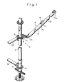
- FIGS. 1 through 3 illustrate a support and a length adjusting device associated therewith according to an embodiment of the present invention.
- the support 6 is used as a horizontal member or a diagonal member of a prefabricated scaffold or a timber structure A for building construction and civil engineering.
- the prefabricated scaffold A is composed of a number of vertical main supports or standards 7 and horizontal members 10 each extending horizontally in a given direction joined with two adjacent ones of the standards 7 via a pair of flanges 8 (one of each pair being shown) and a pair of shoes 9 (one of each pair being shown).
- An adjacent pair of standards may further be joined together by a diagonal member or support 6.
- the support 6 thus connected reinforces the standards 7 and the horizontal members 10.
- the support 6 is joined to the adjacent standards 7 via a pair of flanges 8 (one being shown) and a pair of shoes 11(one being shown).
- the length of the support 6 is adjustable to conform to the width between the adjacent standards 7.
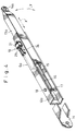
- the support 6, as shown in FIGS. 2 and 3, is composed of a circular cylindrical outer tube 12 and an inner tube 13 slidably inserted in the outer tube 12.
- the outer tube 12 has at its one end an integral bracket 14 adapted to be pivotally connected to one of the pair of shoes 11.
- the inner tube 13 has at its outer end an integral bracket 14a adapted to be pivotally joined with the other shoe 11.
- the inner tube 13 has an inner end which is attached by welding, for example, to an elongated connecting plate 15.
- the connecting plate 15 has an oblong hole 16 extending centrally along a longitudinal axis of the connecting plate 15.
- the connecting plate 15 may be connected directly to the inner end of the inner tube 13, or alternatively it may have an end fitted deeply in the inner end portion of the inner tube 13, as shown in FIG. 2 and 3, so as to reinforce the inner tube 13.
- a connecting rod 17 serving as a support shaft extends diametrically through the outer tube 12 at a position adjacent to the one end or the bracket 14.
- the connecting rod 17 also extends through the oblong hole 16 in the connecting plate 15.
- a pair of nuts 18 is threaded over opposite ends of the connecting rod 17 to securely fasten rod 17 to the outer tube 12 and hence to retain the inner tube 13.
- the inner tube 13 is coupled with the outer tube 12 via the oblong hole 16 and the connecting rod 17 such that the inner tube 13 is movable in the axial direction relative to the outer tube 12 within the length of the oblong hole 16 or within a distance defined between the solid-lined position of the connecting rod 17 and the phantom-lined position of the connecting rod 17 in Fig 2.
- a total or combined length of the outer tube 12 and the inner tube 13 can, therefore, be adjusted in proportion to the distance or extent of relative movement between the inner and outer tubes 13, 12.
- the support 6 includes a length adjusting device 19, described below, for fixing the length of the support.
- the length adjusting device 19 generally comprises an opening 20 extending radially through the outer tube 12 at a given position on the body of the outer tube 12, a hollow housing 21 mounted on an outer surface of the outer tube 12 in confronting relation to (ie adjacent) the opening 20, a spacer 22 radially movably received in the opening 20 and confronted with (ie adjacent) an outer surface of the inner tube 13, and a wedge 24 movably inserted in a space 23 defined in the housing 21 along the axial direction of the housing 21, the wedge 24 being movable in the axial direction of the support 6.
- the housing 21 and the opening 20 in the illustrated embodiment extend in the axial direction of the outer tube 12. They may extend in the circumferential direction of the outer tube 12 in which instance the wedge 24 is movable in a tangential direction of the outer tube 12.
- the outer tube 12 may have an end extension projecting continuously from one end of the outer tube 12, and the housing 21 is mounted on the end extension.
- the opening 20 is formed in the end extension of the outer tube 12.
- the spacer 22 includes an elongated body 22a having on its under surface one or more teeth 22b and, an upper surface shaped to provide a taper surface 22c.
- the teeth 22b are normally held in engagement with the outer surface of the inner tube 13.
- the teeth 22b may be composed of a plurality of sharp or pointed projections or a plurality of ribs having a triangular cross section. In any case, it is desirable that the teeth 22b are engageable in point-contact or in linear-contact with the outer surface of the inner tube 13.
- the under surface of the body 22a of the spacer 22 is preferably curved to conform to the shape of the outer surface of the inner tube 13.
- the teeth 22b may be composed of a combination of one or more teeth so profiled as to secure the point-contact with the inner tube 13 and one or more teeth so profiled as to secure the linear-contact with the inner tube 13.
- the wedge 24 includes an elongated body 24a having a taper surface 24b formed on the under surface of the body 24a for sliding engagement with the taper surface 22c of the spacer 22, a horizontal surface 24c formed on an outer surface of the body 24a adjacent to a front end thereof for sliding engagement with an inner peripheral surface of the housing 19, and a recessed portion 24d formed in the outer surface of the body 24a adjacent to the rear end thereof for a purpose described later.
- the recessed portion 24d receives therein a stopper 25 having a U-shaped cross section.
- the stopper 25 is pivotally connected by a pivot pin 26 to the wedge 24, with a spring 27 acting between an outer surface of the recessed portion 24d and the stopper 25 to urge one or the front end of the stopper 25 upwardly.
- the stopper 25 is used as an indicator which enables visual confirmation of the tightening condition of the wedge 24.
- the indicator may be composed of a mark or a line provided on the upper surface or a side surface of the body 24a of the wedge 24.
- FIG. 2 shows a condition in which the wedge 24 is not driven or tightened.
- the spacer 22 is not subjected to an external force, so that the inner tube 13 is displaceable inwardly and outwardly relative to the outer tube 12 until a desired length of the support 6 is determined.
- the wedge 24 When the inner tube 13 is slidably moved to a position corresponding to the desried length of the support 6, the wedge 24 is forced or driven in a direction toward the bracket 14a shown in FIG. 2. With this movement of the wedge 24, the taper surface 24b of the wedge 24 is brought into sliding engagement with the upper taper surface 22c of the spacer 22 whereupon the movement of the wedge 24 in the axial direction of the inner tube 13 is translated into a movement of the spacer 22 in a radially inward direction normal to the axis of the inner tube 13. Thus, the teeth 22b on the spacer 22 are forced against the outer surface of the inner tube 13.
- the inner tube 13 is firmly gripped via the teeth 22b between the spacer 22 and an inner peripheral surface of the outer tube 12 against axial displacement relative to outer tube 12.
- the desired length of the support 6 is secured.
- the operator inserts the stopper 25 into the housing 21 together with the wedge 24 while depressing with his finger the front end of the stopper 25 against the force of the spring 27. Accordingly, when the stopper 25 is inserted in the housing 21, it can be confirmed that the wedge 24 is completely driven. In contrast, so long as the stopper 25 is exposed from the housing 21, an unintentional failure to drive the wedge 24 or an incomplete driving or tightening condition of the wedge 24 can be visually confirmed.
- the wedge 24 When the wedge 24 is driven or hit in the opposite direction, the wedge 24 is loosened whereupon the spacer 22 is released from the external force, i.e., the tightening force. Now, the inner tube 13 is placed again in a condition slidably movable relative to the outer tube 12.
- FIG. 4 shows a modified form of the support according to another embodiment of the present invention.
- the structure, operation and effects of the modified support 6a are substantially the same as those described in connection with FIG. 2.
- the support 6a is composed of an outer tube 12a having a substantially U-shaped cross-section, and an inner tube 13a having a square cross section and slidably inserted in the U-shaped outer tube 12a.
- Other structural and operational details of the support 6a are the same as those of the support 6 shown in FIG. 2. Therefore, the corresponding parts are designated by the same reference characters, and a detailed description thereof will be omitted.
- the support 6a shown in FIG. 4 is slidably movable in the axial direction as indicated by the arrow X and also is pivotally movable about a connecting rod 17 in a direction indicated by the arrow Y. With this pivoted arrangement, the inner tube 13a can readily be displaced to the outside of the outer tube 12a where repair and replacement of the inner tube 13a can be achieved with utmost ease.
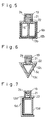
- FIGS. 5 through 7 illustrate various different supports according to further embodiments of the present invention.
- the support 6b shown in FIG. 5 is composed of an outer tube 12b and an outer tube 13b both having square cross section of different sizes.
- the support 6c shown in FIG. 6 is composed of an outer tube 12c having a triangular cross section, and an inner tube 13c having a triangular cross section complementary in contour to the shape of the outer tube 13b.
- the support 6d shown in FIG. 7 is composed of an outer tube 12d having a substantially U-shaped cross section with one side open, and an inner tube 13d having a rectangular cross section.
- This support 6d has substantially the same operation as the support 6a according to the embodiment of FIG. 4.
- Length adjusting devices 19 shown in FIGS. 5 - 7, respectively, are the same as one previously described with respect to the first and second embodiments shown in FIGS. 2 and 4, respectively. Therefore, the corresponding parts are designated by the same reference characters, and a detailed description thereof will be omitted.
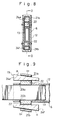
- FIGS. 8 and 9 show length adjusting device associated with a support according to another embodiment of the present invention.
- the length adjusting device in this embodiment is composed of a pair of diametrically opposed length adjusting mechanisms or units.
- An outer tube and an inner tube jointly constituting the support may be the same as one of those shown in FIG. 2 and FIGS. 5 - 7.
- the outer tube 12 and the inner tube 13 slidably inserted in the outer tube 12 jointly constitute the support 6.
- the outer tube 12 has a pair of diametrically opposed first and second openings 20a and 20b extending radially through the outer tube 12 at a given position.
- a first hollow housing 21a and a second hollow housing 21b are mounted on the outer tube 12 in confronting relation to the first and second openings 20a, 20b, respectively.
- First and second identical spacers 22, 22 are radially movably received in the first and second openings 20a, 20b, respectively, and are confronted with , or adjacent, an outer surface of the inner tube 13.
- a first wedge 24e and a second wedge 24f are axially movably inserted in the first and second housings 21a, 21b, respectively, and are confronted with , or adjacent, the first and second spacers 22, 22, respectively.
- first and second wedges 24e, 24f are each provided with a stopper which serves as an indicator and which is the same as the stopper 25 shown in FIG. 2.
- the first and second spacers 22, 22 each have a flat upper surface and a flat lower surface.
- the first and second wedges 24e, 24f each have a flat inner surface and a tapered outer surface a.
- the first and second housings 21a, 21b have first and second tapered inner peripheral surfaces b1 and b2, respectively, sloping or tapering off in the opposite directions.
- the combination of the surfaces of the spacers 22, 22, wedges 24e. 24f and housings 21a, 21b should by no means be limited to one shown in the illustrated embodiment, but may be changed in various ways on condition that when the wedges 24e, 24f are driven, the wedges 24e, 24f are guided in the axial direction of the support, while the spacers 22, 22 are displaced in the radially inward directions of the support.
- the support of this embodiment is particularly suitable for an application in which the wedges are driven from only one direction.
- the tapered surfaces b1, b2 of the first and second wedges 24e, 24f are tapering off in the opposite directions, the first and second wedges 24e, 24f are driven in the opposite directions to tighten the spacers 22, 22.
- first wedge 24c or the second wedge 24f can be driven, and the drivable one wedge 24c or 24f will produce a tightening force sufficient to lock the inner tube 13 in position against axial displacement relative to outer tube 12.
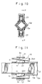
- FIGS. 10 and 11 show an embodiment of the present invention which relates to a modification of the embodiment shown in FIG. 7.
- an outer tube 12e having a rhomboidal cross section and an inner tube 13e having a rhomboidal cross section and slidably inserted in the outer tube 12e form a support 6.
- First and second housings 21, 21 each have a flat inner peripheral surface b3, b3.
- First and second wedges 24e, 24f each have a flat outer surface, and a tapered inner peripheral surface a, a.
- First and second spacers 22, 22 each have a tapered outer surface c1, c2. The wedges 24e, 24f are driven from the same direction.
- the length adjusting device 19 of this embodiment can be manipulated easily and is also able to produce a great tightening force.
- Other details in structure, operation and effects of this invention are substantially the same as those of the embodiments shown in FIG. 2 and FIG. 7.
- the length adjusting devices provided in accordance with this invention have various advantages enumerated below.
Landscapes
- Engineering & Computer Science (AREA)
- Architecture (AREA)
- Mechanical Engineering (AREA)
- Civil Engineering (AREA)
- Structural Engineering (AREA)
- Mutual Connection Of Rods And Tubes (AREA)
- Forms Removed On Construction Sites Or Auxiliary Members Thereof (AREA)
- Ladders (AREA)
- Devices For Conveying Motion By Means Of Endless Flexible Members (AREA)
- Registering, Tensioning, Guiding Webs, And Rollers Therefor (AREA)
- Mechanical Treatment Of Semiconductor (AREA)
- Storage Of Web-Like Or Filamentary Materials (AREA)
- Unwinding Webs (AREA)
- Holders For Apparel And Elements Relating To Apparel (AREA)
- Clamps And Clips (AREA)
Applications Claiming Priority (2)
| Application Number | Priority Date | Filing Date | Title |
|---|---|---|---|
| JP318940/93 | 1993-11-25 | ||
| JP5318940A JP2593791B2 (ja) | 1993-11-25 | 1993-11-25 | 支柱の長さ調整装置 |
Publications (2)
| Publication Number | Publication Date |
|---|---|
| EP0655538A1 true EP0655538A1 (de) | 1995-05-31 |
| EP0655538B1 EP0655538B1 (de) | 1998-07-15 |
Family
ID=18104691
Family Applications (1)
| Application Number | Title | Priority Date | Filing Date |
|---|---|---|---|
| EP94308692A Expired - Lifetime EP0655538B1 (de) | 1993-11-25 | 1994-11-24 | Längenverstellbare Stütze |
Country Status (10)
| Country | Link |
|---|---|
| US (1) | US5590862A (de) |
| EP (1) | EP0655538B1 (de) |
| JP (1) | JP2593791B2 (de) |
| KR (1) | KR0147865B1 (de) |
| CN (1) | CN1108339A (de) |
| AT (1) | ATE168439T1 (de) |
| CA (1) | CA2135957A1 (de) |
| DE (1) | DE69411679D1 (de) |
| ES (1) | ES2119091T3 (de) |
| TW (1) | TW255937B (de) |
Cited By (4)
| Publication number | Priority date | Publication date | Assignee | Title |
|---|---|---|---|---|
| EP1489248A3 (de) * | 2003-05-22 | 2005-11-16 | Scafom International B.V. | Ausziehbarer Gerüstquerbalken |
| EP2097599B1 (de) * | 2006-12-21 | 2016-04-20 | Stylaxion S.A.R.L. | Mobiles verankerungs- und fallverhinderungsgerät |
| CN112211392A (zh) * | 2020-09-28 | 2021-01-12 | 安徽长青建筑制品有限公司 | 一种建筑施工用脚手架支撑加固结构 |
| EP3839172A1 (de) * | 2019-12-20 | 2021-06-23 | Tobler AG | Geländerholm zur montage eines vorlaufenden geländers, vorlaufendes geländer zur temporären fallsicherung einer neu zu erstellenden gerüstetage, gerüst für bau-, reparatur- und/oder montagearbeiten und verfahren zum aufbau eines gerüsts |
Families Citing this family (10)
| Publication number | Priority date | Publication date | Assignee | Title |
|---|---|---|---|---|
| US6250715B1 (en) * | 1998-01-21 | 2001-06-26 | Herman Miller, Inc. | Chair |
| KR101104139B1 (ko) * | 2009-02-09 | 2012-01-13 | 한국산업안전보건공단 | 거푸집 동바리의 수평연결장치 |
| CN102094515B (zh) * | 2010-12-24 | 2012-09-05 | 浙江中南建设集团有限公司 | 一种脚手架 |
| KR101420378B1 (ko) * | 2012-12-18 | 2014-07-16 | 최완석 | 지지 비계 |
| JP6574152B2 (ja) * | 2016-09-01 | 2019-09-11 | 日建リース工業株式会社 | 仮設足場用の繋ぎ材および仮設足場の構築方法 |
| CN109025243A (zh) * | 2018-08-03 | 2018-12-18 | 江苏国舜速接架有限公司 | 一种新型承插型盘扣式速接架 |
| KR102139864B1 (ko) * | 2018-10-08 | 2020-07-30 | 장윤근 | 거푸집 서포트의 가로 연결장치 |
| EP3772559B1 (de) * | 2019-08-05 | 2023-12-13 | Sistemas Técnicos De Encofrados, S.A. | Verankerungssystem mit diagonalaussteifung und schalungsstrebe |
| KR102303557B1 (ko) | 2020-01-06 | 2021-09-23 | 한국철도공사 | 유지보수용 슬라이딩 도어가 설치되는 방음벽 |
| CN112502446A (zh) * | 2020-11-03 | 2021-03-16 | 中国一冶集团有限公司 | 一种承插式中心筒临时支撑及其使用方法 |
Citations (5)
| Publication number | Priority date | Publication date | Assignee | Title |
|---|---|---|---|---|
| US1847660A (en) * | 1927-03-11 | 1932-03-01 | Charles M Markham | Adjustable shore |
| FR1147098A (fr) * | 1955-02-14 | 1957-11-19 | Props Establishment | étançon métallique réglable |
| FR1192700A (fr) * | 1957-03-13 | 1959-10-28 | Schwarz Kg Hermann | Collier en deux éléments utilisable pour le serrage d'une pièce cylindrique |
| GB1106186A (en) * | 1964-05-27 | 1968-03-13 | Wouter Van Wetering | Tubular scaffolding |
| FR2205913A5 (de) * | 1972-11-03 | 1974-05-31 | Peri Werk Schwoerer Kg Artur |
Family Cites Families (11)
| Publication number | Priority date | Publication date | Assignee | Title |
|---|---|---|---|---|
| DE247236C (de) * | ||||
| BE508417A (de) * | ||||
| GB294913A (en) * | 1927-04-29 | 1928-07-30 | Charles Lloyd Maccarthy | Improvements in adjustable pit props |
| DE630073C (de) * | 1934-01-31 | 1936-05-19 | Ver Stahlwerke Akt Ges | Nachgiebiger eiserner Grubenstempel |
| DE813539C (de) * | 1949-03-24 | 1951-09-13 | Josef Brand | Nachgiebiger, zweiteiliger Grubenstempel |
| US2747828A (en) * | 1950-04-18 | 1956-05-29 | Becorit Grubenausbau Gmbh | Mine post |
| DE851490C (de) * | 1950-09-13 | 1952-10-06 | Georg Bachmann | Nachgiebiger Grubenstempel |
| FR1101344A (fr) * | 1953-07-10 | 1955-10-05 | étançon de mine en deux éléments avec plaque de serrage et mécanisme de clavetage | |
| DE1113192B (de) * | 1960-05-09 | 1961-08-31 | Karl Gerlach | Mehrteiliger Grubenstempel mit Reibungsschloss |
| FR1281995A (fr) * | 1960-11-26 | 1962-01-19 | étançon de mine en plusieurs éléments et à verrouillage par friction | |
| JPS5230196U (de) * | 1975-08-25 | 1977-03-02 |
-
1993
- 1993-11-25 JP JP5318940A patent/JP2593791B2/ja not_active Expired - Fee Related
-
1994
- 1994-11-09 KR KR1019940029244A patent/KR0147865B1/ko not_active IP Right Cessation
- 1994-11-11 TW TW083110443A patent/TW255937B/zh not_active IP Right Cessation
- 1994-11-16 CA CA002135957A patent/CA2135957A1/en not_active Abandoned
- 1994-11-18 US US08/342,342 patent/US5590862A/en not_active Expired - Fee Related
- 1994-11-24 ES ES94308692T patent/ES2119091T3/es not_active Expired - Lifetime
- 1994-11-24 DE DE69411679T patent/DE69411679D1/de not_active Expired - Lifetime
- 1994-11-24 AT AT94308692T patent/ATE168439T1/de not_active IP Right Cessation
- 1994-11-24 EP EP94308692A patent/EP0655538B1/de not_active Expired - Lifetime
- 1994-11-25 CN CN94118891A patent/CN1108339A/zh active Pending
Patent Citations (5)
| Publication number | Priority date | Publication date | Assignee | Title |
|---|---|---|---|---|
| US1847660A (en) * | 1927-03-11 | 1932-03-01 | Charles M Markham | Adjustable shore |
| FR1147098A (fr) * | 1955-02-14 | 1957-11-19 | Props Establishment | étançon métallique réglable |
| FR1192700A (fr) * | 1957-03-13 | 1959-10-28 | Schwarz Kg Hermann | Collier en deux éléments utilisable pour le serrage d'une pièce cylindrique |
| GB1106186A (en) * | 1964-05-27 | 1968-03-13 | Wouter Van Wetering | Tubular scaffolding |
| FR2205913A5 (de) * | 1972-11-03 | 1974-05-31 | Peri Werk Schwoerer Kg Artur |
Cited By (4)
| Publication number | Priority date | Publication date | Assignee | Title |
|---|---|---|---|---|
| EP1489248A3 (de) * | 2003-05-22 | 2005-11-16 | Scafom International B.V. | Ausziehbarer Gerüstquerbalken |
| EP2097599B1 (de) * | 2006-12-21 | 2016-04-20 | Stylaxion S.A.R.L. | Mobiles verankerungs- und fallverhinderungsgerät |
| EP3839172A1 (de) * | 2019-12-20 | 2021-06-23 | Tobler AG | Geländerholm zur montage eines vorlaufenden geländers, vorlaufendes geländer zur temporären fallsicherung einer neu zu erstellenden gerüstetage, gerüst für bau-, reparatur- und/oder montagearbeiten und verfahren zum aufbau eines gerüsts |
| CN112211392A (zh) * | 2020-09-28 | 2021-01-12 | 安徽长青建筑制品有限公司 | 一种建筑施工用脚手架支撑加固结构 |
Also Published As
| Publication number | Publication date |
|---|---|
| KR0147865B1 (ko) | 1998-09-15 |
| EP0655538B1 (de) | 1998-07-15 |
| ATE168439T1 (de) | 1998-08-15 |
| ES2119091T3 (es) | 1998-10-01 |
| DE69411679D1 (de) | 1998-08-20 |
| KR950014511A (ko) | 1995-06-16 |
| JPH07150762A (ja) | 1995-06-13 |
| TW255937B (de) | 1995-09-01 |
| US5590862A (en) | 1997-01-07 |
| CA2135957A1 (en) | 1995-05-26 |
| JP2593791B2 (ja) | 1997-03-26 |
| CN1108339A (zh) | 1995-09-13 |
Similar Documents
| Publication | Publication Date | Title |
|---|---|---|
| EP0655538B1 (de) | Längenverstellbare Stütze | |
| US5411113A (en) | Aluminum scaffold system | |
| US4445307A (en) | Scaffold joint for a scaffold structure | |
| EP0590806B1 (de) | Klemmverbindungseinrichtung für Rohrabschnitte | |
| JPH02178442A (ja) | 支柱の連結方法及び支柱装置 | |
| KR20070054417A (ko) | 나사 마디 철근의 이음을 위한 나사형 슬리브 | |
| US5868223A (en) | Flange-type scaffold joint adapted to resist loosening of wedge in response to vibration and tapping | |
| EP0044044A2 (de) | Vorrichtung für Gerüste | |
| JPH08312164A (ja) | 支柱用クランプ及びそのクランプを備える補強材 | |
| US5572838A (en) | Strongback attachment system | |
| US9487961B2 (en) | Connecting device for formwork boards | |
| AU610572B2 (en) | Coupler | |
| CN111566294A (zh) | 脚手架管用夹组件 | |
| KR102050079B1 (ko) | 비계파이프 결합용 체결장치 | |
| EP0004179A1 (de) | Kupplung für Rohrgerüste | |
| EP0473394B1 (de) | Gerüststrukturen | |
| KR102136596B1 (ko) | 시스템 비계 보호캡 | |
| KR200164131Y1 (ko) | 비계용다용도클램프 | |
| JPH0424170Y2 (de) | ||
| JP3648528B2 (ja) | 分割型ボックスカルバートの組立方法及び該組立に使用する緊張材連結用治具 | |
| JPS631713Y2 (de) | ||
| WO2024042325A1 (en) | Temporary fence panel coupler | |
| GB2125881A (en) | Couplings for scaffold tubes | |
| GB2156028A (en) | Scaffolding cross members | |
| JPH10245997A (ja) | 柱の立設・固定装置 |
Legal Events
| Date | Code | Title | Description |
|---|---|---|---|
| PUAI | Public reference made under article 153(3) epc to a published international application that has entered the european phase |
Free format text: ORIGINAL CODE: 0009012 |
|
| AK | Designated contracting states |
Kind code of ref document: A1 Designated state(s): AT BE CH DE DK ES FR GB GR IT LI NL SE |
|
| 17P | Request for examination filed |
Effective date: 19951102 |
|
| 17Q | First examination report despatched |
Effective date: 19961024 |
|
| GRAG | Despatch of communication of intention to grant |
Free format text: ORIGINAL CODE: EPIDOS AGRA |
|
| GRAG | Despatch of communication of intention to grant |
Free format text: ORIGINAL CODE: EPIDOS AGRA |
|
| GRAH | Despatch of communication of intention to grant a patent |
Free format text: ORIGINAL CODE: EPIDOS IGRA |
|
| GRAH | Despatch of communication of intention to grant a patent |
Free format text: ORIGINAL CODE: EPIDOS IGRA |
|
| GRAA | (expected) grant |
Free format text: ORIGINAL CODE: 0009210 |
|
| AK | Designated contracting states |
Kind code of ref document: B1 Designated state(s): AT BE CH DE DK ES FR GB GR IT LI NL SE |
|
| PG25 | Lapsed in a contracting state [announced via postgrant information from national office to epo] |
Ref country code: NL Free format text: LAPSE BECAUSE OF FAILURE TO SUBMIT A TRANSLATION OF THE DESCRIPTION OR TO PAY THE FEE WITHIN THE PRESCRIBED TIME-LIMIT Effective date: 19980715 Ref country code: LI Free format text: LAPSE BECAUSE OF FAILURE TO SUBMIT A TRANSLATION OF THE DESCRIPTION OR TO PAY THE FEE WITHIN THE PRESCRIBED TIME-LIMIT Effective date: 19980715 Ref country code: GR Free format text: LAPSE BECAUSE OF NON-PAYMENT OF DUE FEES Effective date: 19980715 Ref country code: CH Free format text: LAPSE BECAUSE OF FAILURE TO SUBMIT A TRANSLATION OF THE DESCRIPTION OR TO PAY THE FEE WITHIN THE PRESCRIBED TIME-LIMIT Effective date: 19980715 Ref country code: BE Free format text: LAPSE BECAUSE OF FAILURE TO SUBMIT A TRANSLATION OF THE DESCRIPTION OR TO PAY THE FEE WITHIN THE PRESCRIBED TIME-LIMIT Effective date: 19980715 Ref country code: AT Free format text: LAPSE BECAUSE OF FAILURE TO SUBMIT A TRANSLATION OF THE DESCRIPTION OR TO PAY THE FEE WITHIN THE PRESCRIBED TIME-LIMIT Effective date: 19980715 |
|
| REF | Corresponds to: |
Ref document number: 168439 Country of ref document: AT Date of ref document: 19980815 Kind code of ref document: T |
|
| REG | Reference to a national code |
Ref country code: CH Ref legal event code: EP |
|
| REF | Corresponds to: |
Ref document number: 69411679 Country of ref document: DE Date of ref document: 19980820 |
|
| ET | Fr: translation filed | ||
| REG | Reference to a national code |
Ref country code: ES Ref legal event code: FG2A Ref document number: 2119091 Country of ref document: ES Kind code of ref document: T3 |
|
| PG25 | Lapsed in a contracting state [announced via postgrant information from national office to epo] |
Ref country code: SE Free format text: LAPSE BECAUSE OF FAILURE TO SUBMIT A TRANSLATION OF THE DESCRIPTION OR TO PAY THE FEE WITHIN THE PRESCRIBED TIME-LIMIT Effective date: 19981015 Ref country code: DK Free format text: LAPSE BECAUSE OF FAILURE TO SUBMIT A TRANSLATION OF THE DESCRIPTION OR TO PAY THE FEE WITHIN THE PRESCRIBED TIME-LIMIT Effective date: 19981015 |
|
| PG25 | Lapsed in a contracting state [announced via postgrant information from national office to epo] |
Ref country code: DE Free format text: LAPSE BECAUSE OF FAILURE TO SUBMIT A TRANSLATION OF THE DESCRIPTION OR TO PAY THE FEE WITHIN THE PRESCRIBED TIME-LIMIT Effective date: 19981016 |
|
| PG25 | Lapsed in a contracting state [announced via postgrant information from national office to epo] |
Ref country code: GB Free format text: LAPSE BECAUSE OF NON-PAYMENT OF DUE FEES Effective date: 19981124 |
|
| PG25 | Lapsed in a contracting state [announced via postgrant information from national office to epo] |
Ref country code: ES Free format text: LAPSE BECAUSE OF NON-PAYMENT OF DUE FEES Effective date: 19981125 |
|
| NLV1 | Nl: lapsed or annulled due to failure to fulfill the requirements of art. 29p and 29m of the patents act | ||
| REG | Reference to a national code |
Ref country code: CH Ref legal event code: PL |
|
| PLBE | No opposition filed within time limit |
Free format text: ORIGINAL CODE: 0009261 |
|
| STAA | Information on the status of an ep patent application or granted ep patent |
Free format text: STATUS: NO OPPOSITION FILED WITHIN TIME LIMIT |
|
| 26N | No opposition filed | ||
| GBPC | Gb: european patent ceased through non-payment of renewal fee |
Effective date: 19981124 |
|
| PG25 | Lapsed in a contracting state [announced via postgrant information from national office to epo] |
Ref country code: FR Free format text: LAPSE BECAUSE OF NON-PAYMENT OF DUE FEES Effective date: 19990730 |
|
| REG | Reference to a national code |
Ref country code: FR Ref legal event code: ST |
|
| REG | Reference to a national code |
Ref country code: ES Ref legal event code: FD2A Effective date: 19991214 |
|
| PG25 | Lapsed in a contracting state [announced via postgrant information from national office to epo] |
Ref country code: IT Free format text: LAPSE BECAUSE OF NON-PAYMENT OF DUE FEES Effective date: 20051124 |