EP0655208B1 - Applicator device for liquids - Google Patents
Applicator device for liquids Download PDFInfo
- Publication number
- EP0655208B1 EP0655208B1 EP94402607A EP94402607A EP0655208B1 EP 0655208 B1 EP0655208 B1 EP 0655208B1 EP 94402607 A EP94402607 A EP 94402607A EP 94402607 A EP94402607 A EP 94402607A EP 0655208 B1 EP0655208 B1 EP 0655208B1
- Authority
- EP
- European Patent Office
- Prior art keywords
- dispenser
- valve
- dispenser head
- liquid
- head
- Prior art date
- Legal status (The legal status is an assumption and is not a legal conclusion. Google has not performed a legal analysis and makes no representation as to the accuracy of the status listed.)
- Expired - Lifetime
Links
Images
Classifications
-
- B—PERFORMING OPERATIONS; TRANSPORTING
- B65—CONVEYING; PACKING; STORING; HANDLING THIN OR FILAMENTARY MATERIAL
- B65D—CONTAINERS FOR STORAGE OR TRANSPORT OF ARTICLES OR MATERIALS, e.g. BAGS, BARRELS, BOTTLES, BOXES, CANS, CARTONS, CRATES, DRUMS, JARS, TANKS, HOPPERS, FORWARDING CONTAINERS; ACCESSORIES, CLOSURES, OR FITTINGS THEREFOR; PACKAGING ELEMENTS; PACKAGES
- B65D83/00—Containers or packages with special means for dispensing contents
- B65D83/14—Containers or packages with special means for dispensing contents for delivery of liquid or semi-liquid contents by internal gaseous pressure, i.e. aerosol containers comprising propellant for a product delivered by a propellant
- B65D83/28—Nozzles, nozzle fittings or accessories specially adapted therefor
- B65D83/285—Nozzles, nozzle fittings or accessories specially adapted therefor for applying the contents, e.g. brushes, rollers, pads, spoons, razors, scrapers
-
- A—HUMAN NECESSITIES
- A45—HAND OR TRAVELLING ARTICLES
- A45D—HAIRDRESSING OR SHAVING EQUIPMENT; EQUIPMENT FOR COSMETICS OR COSMETIC TREATMENTS, e.g. FOR MANICURING OR PEDICURING
- A45D34/00—Containers or accessories specially adapted for handling liquid toiletry or cosmetic substances, e.g. perfumes
- A45D34/04—Appliances specially adapted for applying liquid, e.g. using roller or ball
-
- A—HUMAN NECESSITIES
- A45—HAND OR TRAVELLING ARTICLES
- A45D—HAIRDRESSING OR SHAVING EQUIPMENT; EQUIPMENT FOR COSMETICS OR COSMETIC TREATMENTS, e.g. FOR MANICURING OR PEDICURING
- A45D2200/00—Details not otherwise provided for in A45D
- A45D2200/10—Details of applicators
- A45D2200/1009—Applicators comprising a pad, tissue, sponge, or the like
- A45D2200/1018—Applicators comprising a pad, tissue, sponge, or the like comprising a pad, i.e. a cushion-like mass of soft material, with or without gripping means
Definitions
- the present invention relates to an applicator device for liquid and in particular a device which can be used for application, for example topically, on the skin of a cosmetic product or dermopharmaceutical, such as a deodorant for example.
- the use of aerosol delivery involves ejection in the atmosphere, along with the liquid particles of aerosol, pressurizing gas; if you pressurize with a compressed gas not liquefied, for example by air, the pressure of distribution decreases as the tank is discharged, from so that at the end of distribution the aerosol particles are too large; if pressurization with chlorofluoroalkane is ensured partially liquefied, air pollution is generated; if, finally, we pressurize with butane or propane partially liquefied, the product can in no way be considered as hypoallergenic, given the risk faced by some subject to inhalation of the propellant.
- a device comprising a container for the liquid to be applied on a surface to be treated and a dispensing dome connected to said container by a dispensing head, the dispensing dome being produced in a porous material suitable for applying the liquid by simple rubbing of the external face of said dome on the surface to be treated, the container being a pressurized tank fitted with a distribution valve, the dome dispenser being carried by a support, which constitutes an element of the dispensing head and is mechanically linked to a nozzle suitable for cooperate with said valve to cause it to open under the action mechanical stress exerted on the dispensing dome, the liquid ejected from the tank during said opening being channeled to through said nozzle towards the face of the distributor dome, which is opposite on the external face of said dome, the dispensing head comprising a attachment member for securing said head with the tank and the attachment member being a rigid skirt fixed to the tank by snap-fast
- Such a device has the advantage of not requiring any prior return to the application; however, its use is not easy: on the one hand, the distributor dome is guided along the axis of the valve stem distribution that it is necessary to operate along this axis for its opening while a transverse movement must be given to the device for spreading the product on the surface to be treated, and other apart, this axial force of opening the valve is carried out against elastic means specific to the dispensing valve and it is difficult to adjust or adjust the distribution of the product.
- the object of the present invention is to propose a device applicator of the above type, which eliminates all the disadvantages above mentioned and which can be realized for a cost price reduced.
- the device according to the invention can be used for the distribution of cosmetic or dermopharmaceutical products but is in no way limited to this type of application: it can be used in all cases where you want to spread a liquid on a surface at using an applicator. In case it is an application topically on the skin of a user, the device according to the invention therefore has the advantage of not requiring any prior return to application, which is an added benefit for the user, in particular for the application of deodorants or antiperspirants in the armpits.
- a flexible element connects said attachment member and the distributor dome support.
- the rigid skirt is connected in the vicinity of its border greater than a cylindrical wall, which constitutes the flexible element.
- the dispensing head is made in one piece by plastic molding.
- applicator device according to the invention may have all three of the above features simultaneously.
- the dome support dispenser is a cup having, on at least one zone, a depression likely to collect an excess of liquid ejected by the valve.
- the tank is a can cylindrical, the top of which is shaped like a warhead and carries the valve distribution, a latching groove being provided in the area of connection of the cylindrical wall and the ogive wall, the skirt rigid being cylindrical and bearing in the vicinity of one of its edges a latching means able to cooperate with said groove latching.
- the flexible element connects the area of the skirt rigid, which is furthest from the snap zone, at the periphery support for the dispensing dome; the rigid skirt and the flexible element may consist of a continuous wall surrounding the valve dispensing when the dispensing head is snapped onto the tank; but the flexible element could also be produced under discontinuous shape by a plurality of successive sectors.
- the distribution head is, apart from the medium (s) for hanging the dispensing dome, a piece of revolution around a axis.
- the dispensing valve has a rod emerging, which is partially embedded, in a sealed manner, in a internal channeling of the nozzle; the tip can be placed in the central zone of the support of the dispensing dome, said end piece having a cylindrical shape along the axis of which is formed its pipe internal.
- valve distribution valve or an opening valve by lateral tilting of its emerging stem.
- the dispensing dome may be made of a material ceramic or plastic sintered, in particular of a material obtained by compression of plastic particles; for example, we can use a sinter obtained by compression of calibrated balls of polyethylene, said sintered material having a porosity of between 10 microns and 500 microns.
- the choice of porosity is generally made in taking into account two parameters, on the one hand, the flow rate desired for the liquid to be applied and, on the other hand, the surface condition of the porous dome, which must be compatible with the surface to be treated envision.
- the dispensing dome is made of a sintered material plastic, it can be made of synthetic resins such as high or low density polyethylenes, polypropylenes or polyvinyl fluorides, the preferred porosity range being 10 at 200 microns.
- the dispensing dome of the device according to the invention can also be made using open cell foam by example a polyethylene foam; this foam can be covered with a canvas for the comfort of the application.
- the dispensing dome consists of a non-deformable material.
- channels which are substantially radial between the internal face of the support and the lower face of the dome distributor can be made in the dome dispenser itself and / or in the support wall: these channels have the advantage of ensuring a good distribution of the liquid to be distributed for that the external face of the dispensing dome is uniformly supplied by said liquid.
- the application face of the dome distributor has a roughness such that the average Ra of the deviations of roughness is between 0.5 ⁇ m and 100 ⁇ m, preferably between 6 ⁇ m and 50 ⁇ m.
- Another advantage of the device according to the invention comes from the fact that when the valve is opened, the liquid is ejected towards the dome distributor by the pressurizing agent but that given that it is not an aerosol distribution, the pressurizing agent can remain entirely inside the container: there is therefore no risk of air pollution and no destruction of character possibly hypoallergenic of the liquid to be dispensed.
- the distribution is done without generating a cloud of liquid particles may be inhaled by the user with a sternutatory effect.
- the device according to the invention does not have no risk of leakage since dead volumes below the dome dispensers are extremely reduced; in case of distribution excessive liquid instant, the liquid collects in the area of the distributor dome, which occupies the depressions of the cup where is set up said distributor dome. It is possible for the user to carry out a voluntary overdose by pressing with a finger on the surface of the dispensing dome before applying to the surface to be treated.
- This tank is a cylindrical can of circular cross section, the top of which is shaped like a warhead 2, which carries, at its upper part, a valve cup secured to the container by a crimping bead 3.
- the valve cup carries, along its axis, a distribution valve 4 which, in the case of this example, is a valve comprising a rod emerging 5; valve 4 is opened by tilting lateral of the emerging rod 5; the valve may be of the type marketed by the company "COSTER" under the reference "TR 120-40".
- a peripheral snap groove 6 In the zone junction of the warhead 2 with the cylindrical wall of the tank 1, we have made a peripheral snap groove 6.
- a pressure was conditioned liquid to be dispensed.
- This liquid can be a liquid composition of body deodorant with a viscosity of approximately 0.003 Pa.s.
- the pressurization can be carried out either by putting the liquid directly in contact with the propellant, either by separating the liquid and the gas propellant by a movable piston or by a flexible deformable pocket, which releases, in the latter case, from the obligation to use the device in a determined position, either valve at the top or valve at the bottom.
- the propellant used was butane, liquid being separated from butane by a movable piston.
- a dispensing head which comprises, on the one hand, a rigid skirt 7, on the other hand, a cup 8, which constitutes the support of a dispensing dome 9 and, finally, a flexible element 10, which connects the cup 8 and the rigid skirt 7.
- the rigid skirt 7 has internally, at its base, an annular latching bead 11, which is intended to cooperate with the latching groove 6
- the rigid skirt 7 is connected in the vicinity of its upper edge 7 a to a cylindrical wall, which constitutes the flexible element 10, the connection being effected in a rounded zone 10 a , the convexity of which is turned towards the latching bead 11.
- the rigid skirt 7 and the flexible element 10 have a generally cylindrical shape and constitute coaxial cylinders.
- the flexible element 10 is connected to the cup 8; said cup 8 has an annular depression 8 a at the bottom of which there are projections which constitute attachment means 12 for the dispensing dome 9.
- the cup 8 is secured to a nozzle 13 of cylindrical shape, said tip having along its axis a conduit 14, the lower portion 14 has a larger diameter, said portion opening to the outside by a frustoconical mouth 14 b.
- the free end is force-engaged over a few millimeters. of the emerging rod 5 of the valve 4 in order to obtain a sealed connection between the rod 5 and the nozzle 13.
- the distributor dome 9 has been put in place, which is constituted by a polyethylene sinter having a porosity of 40 microns.
- the user applies the external surface 9a of the dome 9 against the surface to be treated, for example the skin of an armpit if the liquid packaged in the container 1 is a liquid deodorant. It then moves the device laterally with respect to the armpit, which results in a friction force, which causes the deformation of the flexible element 10, and, therefore, a substantially radial displacement of the cup 8 relative to the reservoir 1 and therefore relative to the axis of the valve 4. There follows a lateral tilting of the emerging rod 5 and therefore an opening of the valve 4 with simultaneous ejection of the liquid conditioned under pressure in the reservoir 1.
- the liquid arrives on the internal face 9b of the dispensing dome 9; it is distributed over this entire internal face and, under the effect of the distribution pressure, it passes through the sintering constituting the distributor dome 9 to come flush with the external face 9 a of said dome.
- the liquid is then distributed by friction on the support to be treated, in this case the armpit skin; if there is an excess of liquid, the friction force decreases, which causes the valve 4 to close under the effect of the elastic return, which exists inside said valve.
- the device which has just been described, is of an extremely reduced cost price because, the whole of the head of distribution constituted by the skirt 7, the flexible element 10 and the cup 8 can be made in one piece by plastic molding.
- the use of this device is particularly reliable since it there can be no leakage.
- the approval of an application topically using this device is very satisfactory because the user feels a soft and non-greasy application with a freshness effect and the application can be carried out directly without turning prior to the device.
Description
La présente invention concerne un dispositif applicateur pour liquide et notamment un dispositif utilisable pour l'application, par voie topique, sur la peau d'un produit à action cosmétique ou dermopharmaceutique, tel qu'un déodorant par exemple.The present invention relates to an applicator device for liquid and in particular a device which can be used for application, for example topically, on the skin of a cosmetic product or dermopharmaceutical, such as a deodorant for example.
Dans le cas particulier de produits tels qu'un déodorant ou un antiperspirant, on a déjà proposé d'assurer l'application au moyen d'un bâton solide, dit "raisin", contenant l'actif à appliquer sur la peau de l'utilisateur ; un tel raisin peut avoir, en section droite, diverses formes choisies en fonction de l'utilisation et il est conditionné dans un étui permettant son déplacement au fur et à mesure de la consommation du raisin. L'inconvénient d'une telle présentation est, d'une part, qu'elle nécessite pour le conditionnement du produit des outillages spéciaux et onéreux et, d'autre part, que la conservation du raisin n'est généralement pas parfaitement assurée, car la composition solide utilisée contient un important pourcentage d'alcool et le conditionnement n'est généralement pas suffisamment étanche pour empêcher l'évaporation de l'alcool. En outre, le confort de l'utilisateur n'est pas parfaitement satisfaisant car l'application d'un raisin sur la peau donne, avec les compositions connues, une impression d'application grasse alors que l'utilisateur souhaite une application non grasse avec un effet rafraichissant.In the particular case of products such as a deodorant or an antiperspirant, it has already been proposed to ensure application by means a solid stick, called "grape", containing the active ingredient to be applied to the skin of the user; such a grape can have, in cross section, various forms chosen according to the use and it is packaged in a case allowing its displacement as and when consumption grape. The disadvantage of such a presentation is, on the one hand, that it requires for the packaging of the product of the tools special and expensive and, on the other hand, that the conservation of the grape is not generally not perfectly assured, because the solid composition used contains a large percentage of alcohol and the packaging is generally not waterproof enough to prevent alcohol from evaporating. In addition, user comfort is not perfectly satisfactory because the application of a grape on the skin gives, with known compositions, an impression oily application when the user wants an application that is not oily with a refreshing effect.
On a déjà proposé de surmonter ces inconvénients en proposant un applicateur qui met en oeuvre une composition liquide contenue dans un flacon sur lequel est fixée une tête de distribution portant un dôme distributeur réalisé en un matériau solide poreux. Ce type de réalisation a été décrit, par exemple, dans le brevet US-A-5 230 579 ou dans le brevet français FR-89-06490. L'inconvénient de ce type de conditionnement est double : d'une part, pour assurer la fermeture du flacon lorsque le produit n'est pas utilisé, il est nécessaire de prévoir une tête de distribution relativement compliquée, ce qui augmente de façon importante le coût du conditionnement ; et d'autre part, pour utiliser le produit, il est nécessaire d'effectuer une action préalable amenant le liquide dans le dôme poreux avec lequel on va assurer l'application : dans le cas des deux brevets antérieurs susmentionnés, cette action est un retournement préalable du flacon pour que le liquide descende par gravité dans le dôme poreux.It has already been proposed to overcome these drawbacks by proposing an applicator which implements a liquid composition contained in a bottle on which a dispensing head is fixed carrying a dispensing dome made of a porous solid material. This type of embodiment has been described, for example, in the patent US-A-5,230,579 or in French patent FR-89-06490. The disadvantage of this type of packaging is twofold: on the one hand, to ensure the closure of the bottle when the product is not used, it is necessary to provide a relatively dispensing head complicated, which significantly increases the cost of conditioning ; and secondly, to use the product, it is necessary to perform a prior action bringing the liquid into the porous dome with which we will ensure the application: in the case of two earlier patents mentioned above, this action is a reversal the bottle so that the liquid descends by gravity into the porous dome.
On a également proposé d'appliquer les produits de ce type sous forme d'aérosol, auquel cas la composition liquide distribuée est parfaitement préservée pendant son stockage puisqu'elle se trouve à l'intérieur d'un récipient pressurisé fermé par une valve. Cependant, ce mode d'application présente des inconvénients importants : en effet, l'application, même lorsqu'elle est bien ciblée, génère un nuage de particules liquides qui est partiellement inhalé par l'utilisateur, d'où il résulte souvent un effet sternutatoire particulièrement désagréable, notamment lors de la toilette du matin dans la salle de bains, voire des réactions plus graves lorsqu'il s'agit de sujets asthmatiques particulièrement sensibles à l'inhalation de particules aérosols. En outre, l'utilisation d'une distribution par aérosol implique l'éjection dans l'atmosphère, en même temps que les particules liquides de l'aérosol, du gaz pressuriseur ; si l'on assure la pressurisation par un gaz comprimé non liquéfié, par exemple par de l'air, la pression de distribution décroít au fur et à mesure de la décharge du réservoir, de sorte qu'en fin de distribution les particules de l'aérosol sont trop grosses ; si l'on assure la pressurisation avec un chlorofluoroalcane partiellement liquéfié, on génère une pollution atmosphérique ; si, enfin, on assure la pressurisation avec du butane ou du propane partiellement liquéfié, le produit ne peut en aucun cas être considéré comme hypoallergénique, étant donné le risque encouru par certains sujets à l'inhalation du propulseur.It has also been proposed to apply products of this type in aerosol form, in which case the liquid composition dispensed is perfectly preserved during storage since it is inside a pressurized container closed by a valve. However, this mode of application has significant drawbacks: in fact, the application, even when it is well targeted, generates a cloud of liquid particles which is partially inhaled by the user, hence it often results in a particularly unpleasant sternutatory effect, especially during the morning toilet in the bathroom, or even more severe reactions in asthmatic subjects particularly sensitive to inhalation of aerosol particles. In in addition, the use of aerosol delivery involves ejection in the atmosphere, along with the liquid particles of aerosol, pressurizing gas; if you pressurize with a compressed gas not liquefied, for example by air, the pressure of distribution decreases as the tank is discharged, from so that at the end of distribution the aerosol particles are too large; if pressurization with chlorofluoroalkane is ensured partially liquefied, air pollution is generated; if, finally, we pressurize with butane or propane partially liquefied, the product can in no way be considered as hypoallergenic, given the risk faced by some subject to inhalation of the propellant.
Dans le but de supprimer les inconvénients mentionnés ci-dessus, on a proposé, selon EP-A-0 374 339, un dispositif applicateur pour liquide comportant un conteneur du liquide à appliquer sur une surface à traiter et un dôme distributeur relié audit conteneur par une tête de distribution, le dôme distributeur étant réalisé en un matériau poreux adapté à l'application du liquide par simple frottement de la face externe dudit dôme sur la surface à traiter, le conteneur étant un réservoir pressurisé équipé d'une valve de distribution, le dôme distributeur étant porté par un support, qui constitue un élément de la tête de distribution et est mécaniquement lié à un embout apte à coopérer avec ladite valve pour provoquer son ouverture sous l'action d'une sollicitation mécanique exercée sur le dôme distributeur, le liquide éjecté hors du réservoir pendant ladite ouverture étant canalisé à travers ledit embout vers la face du dôme distributeur, qui est opposée à la face externe dudit dôme, la tête de distribution comportant un organe d'accrochage permettant de solidariser ladite tête avec le réservoir et l'organe d'accrochage étant une jupe rigide fixée sur le réservoir par encliquetage d'une zone d'encliquetage. Un tel dispositif présente l'intérêt de ne nécessiter aucun retournement préalable à l'application ; toutefois, son utilisation n'est pas aisée : d'une part, le dôme distributeur est guidé selon l'axe de la tige de la valve de distribution qu'il est nécessaire d'actionner selon cet axe pour son ouverture tandis qu'un mouvement transversal doit être donné au dispositif pour l'étalement du produit sur la surface à traiter, et, d'autre part, cet effort axial d'ouverture de la valve est effectué à l'encontre des moyens élastiques propres à la valve de distribution et il est difficile de régler ou doser la distribution du produit.In order to remove the mentioned disadvantages above, according to EP-A-0 374 339, a device has been proposed liquid applicator comprising a container for the liquid to be applied on a surface to be treated and a dispensing dome connected to said container by a dispensing head, the dispensing dome being produced in a porous material suitable for applying the liquid by simple rubbing of the external face of said dome on the surface to be treated, the container being a pressurized tank fitted with a distribution valve, the dome dispenser being carried by a support, which constitutes an element of the dispensing head and is mechanically linked to a nozzle suitable for cooperate with said valve to cause it to open under the action mechanical stress exerted on the dispensing dome, the liquid ejected from the tank during said opening being channeled to through said nozzle towards the face of the distributor dome, which is opposite on the external face of said dome, the dispensing head comprising a attachment member for securing said head with the tank and the attachment member being a rigid skirt fixed to the tank by snap-fastening of a snap-on area. Such a device has the advantage of not requiring any prior return to the application; however, its use is not easy: on the one hand, the distributor dome is guided along the axis of the valve stem distribution that it is necessary to operate along this axis for its opening while a transverse movement must be given to the device for spreading the product on the surface to be treated, and other apart, this axial force of opening the valve is carried out against elastic means specific to the dispensing valve and it is difficult to adjust or adjust the distribution of the product.
La présente invention a pour but de proposer un dispositif applicateur du type ci-dessus, qui supprime tous les inconvénients ci-dessus mentionnés et qui peut être réalisé pour un prix de revient réduit. Le dispositif selon l'invention peut être utilisé pour la distribution de produits à action cosmétique ou dermopharmaceutique mais n'est aucunement limité à ce type d'application : il peut être utilisé dans tous les cas où l'on veut étaler un liquide sur une surface au moyen d'un applicateur. Dans le cas où il s'agit d'une application topique sur la peau d'un utilisateur, le dispositif selon l'invention présente donc l'intérêt de ne nécessiter aucun retournement préalable à l'application, ce qui constitue un avantage supplémentaire pour l'utilisateur, notamment pour l'application des déodorants ou antiperspirants au niveau des aisselles.The object of the present invention is to propose a device applicator of the above type, which eliminates all the disadvantages above mentioned and which can be realized for a cost price reduced. The device according to the invention can be used for the distribution of cosmetic or dermopharmaceutical products but is in no way limited to this type of application: it can be used in all cases where you want to spread a liquid on a surface at using an applicator. In case it is an application topically on the skin of a user, the device according to the invention therefore has the advantage of not requiring any prior return to application, which is an added benefit for the user, in particular for the application of deodorants or antiperspirants in the armpits.
Selon une première caractéristique du dispositif selon l'invention, un élément souple relie ledit organe d'accrochage et le support du dôme distributeur.According to a first characteristic of the device according to the invention, a flexible element connects said attachment member and the distributor dome support.
Selon une autre caractéristique du dispositif selon l'invention, la jupe rigide est reliée au voisinage de sa bordure supérieure à une paroi cylindrique, qui constitue l'élément souple. According to another characteristic of the device according to the invention, the rigid skirt is connected in the vicinity of its border greater than a cylindrical wall, which constitutes the flexible element.
Selon encore une autre caractéristique du dispositif selon l'invention, la tête de distribution est réalisée en une seule pièce par moulage de matière plastique.According to yet another characteristic of the device according the invention, the dispensing head is made in one piece by plastic molding.
Bien entendu, le dispositif applicateur selon l'invention peut comporter simultanément les trois caractéristiques ci-dessus.Of course, the applicator device according to the invention may have all three of the above features simultaneously.
Dans un mode préféré de réalisation, le support du dôme distributeur est une coupelle présentant, sur au moins une zone, une dépression susceptible de recueillir un excès de liquide éjecté par la valve.In a preferred embodiment, the dome support dispenser is a cup having, on at least one zone, a depression likely to collect an excess of liquid ejected by the valve.
Selon une réalisation intéressante, le réservoir est un bidon cylindrique, dont le sommet est conformé en ogive et porte la valve de distribution, une gorge d'encliquetage étant prévue dans la zone de raccordement de la paroi cylindrique et de la paroi en ogive, la jupe rigide étant cylindrique et portant au voisinage d'une de ses bordures un moyen d'encliquetage apte à coopérer avec ladite gorge d'encliquetage.According to an interesting embodiment, the tank is a can cylindrical, the top of which is shaped like a warhead and carries the valve distribution, a latching groove being provided in the area of connection of the cylindrical wall and the ogive wall, the skirt rigid being cylindrical and bearing in the vicinity of one of its edges a latching means able to cooperate with said groove latching.
De préférence, l'élément souple relie la zone de la jupe rigide, qui est la plus éloignée de la zone d'encliquetage, à la périphérie du support du dôme distributeur ; la jupe rigide et l'élément souple peuvent être constitués d'une paroi continue entourant la valve de distribution quand la tête de distribution est encliquetée sur le réservoir; mais l'élément souple pourrait également être réalisé sous forme discontinue par une pluralité de secteurs successifs. Avantageusement, la tête de distribution est, hormis le(s) moyen(s) d'accrochage du dôme distributeur, une pièce de révolution autour d'un axe.Preferably, the flexible element connects the area of the skirt rigid, which is furthest from the snap zone, at the periphery support for the dispensing dome; the rigid skirt and the flexible element may consist of a continuous wall surrounding the valve dispensing when the dispensing head is snapped onto the tank; but the flexible element could also be produced under discontinuous shape by a plurality of successive sectors. Advantageously, the distribution head is, apart from the medium (s) for hanging the dispensing dome, a piece of revolution around a axis.
On préfère que la valve de distribution comporte une tige émergente, qui est partiellement enfoncée, de façon étanche, dans une canalisation interne de l'embout ; l'embout peut être disposé dans la zone centrale du support du dôme distributeur, ledit embout ayant une forme cylindrique selon l'axe de laquelle est ménagée sa canalisation interne.It is preferred that the dispensing valve has a rod emerging, which is partially embedded, in a sealed manner, in a internal channeling of the nozzle; the tip can be placed in the central zone of the support of the dispensing dome, said end piece having a cylindrical shape along the axis of which is formed its pipe internal.
Dans le cas d'un dispositif applicateur destiné à l'application sur la peau d'un produit cosmétique ou dermopharmaceutique, on peut avantageusement prévoir que la valve de distribution soit une valve à ouverture par basculement latéral de sa tige émergente.In the case of an applicator device intended to applying a cosmetic product to the skin or dermopharmaceutical, it can advantageously be provided that the valve distribution valve or an opening valve by lateral tilting of its emerging stem.
Le dôme distributeur peut être constitué d'un matériau fritté céramique ou plastique, notamment d'un matériau obtenu par compression de particules de matière plastique ; par exemple, on peut utiliser un fritté obtenu par compression de billes calibrées de polyéthylène, ledit fritté ayant une porosité comprise entre 10 microns et 500 microns. Le choix de la porosité est généralement effectué en tenant compte de deux paramètres, d'une part, le débit de passage désiré pour le liquide à appliquer et, d'autre part, I'état de surface du dôme poreux, qui doit être compatible avec la surface à traiter que l'on envisage. Pour définir la porosité, de façon connue, on mesure le débit de passage d'un liquide à travers une épaisseur donnée du fritté sous une différence de pression prédéterminée et on en déduit la section équivalente d'une canalisation assurant le même débit dans les mêmes conditions et donc, le diamètre moyen d'un pore quand on connait statistiquement le nombre de pores par unité de surface du dôme. Lorsque le dôme distributeur est réalisé en un fritté de matière plastique, il peut être constitué par des résines synthétiques telles que des polyéthylènes à haute ou basse densité, des polypropylènes ou des fluorures de polyvinyle, la gamme de porosité préférée s'étendant de 10 à 200 microns.The dispensing dome may be made of a material ceramic or plastic sintered, in particular of a material obtained by compression of plastic particles; for example, we can use a sinter obtained by compression of calibrated balls of polyethylene, said sintered material having a porosity of between 10 microns and 500 microns. The choice of porosity is generally made in taking into account two parameters, on the one hand, the flow rate desired for the liquid to be applied and, on the other hand, the surface condition of the porous dome, which must be compatible with the surface to be treated envision. To define the porosity, in a known way, we measure the flow passage of a liquid through a given thickness of the sintered under a predetermined pressure difference and the section is deduced therefrom equivalent of a pipe ensuring the same flow in the same conditions and therefore, the average diameter of a pore when we know statistically the number of pores per unit area of the dome. When the dispensing dome is made of a sintered material plastic, it can be made of synthetic resins such as high or low density polyethylenes, polypropylenes or polyvinyl fluorides, the preferred porosity range being 10 at 200 microns.
Le dôme distributeur du dispositif selon l'invention peut également être réalisé au moyen d'une mousse à cellules ouvertes par exemple une mousse de polyéthylène ; cette mousse peut être recouverte d'une toile pour le confort de l'application.The dispensing dome of the device according to the invention can also be made using open cell foam by example a polyethylene foam; this foam can be covered with a canvas for the comfort of the application.
Avantageusement, le dôme distributeur est constitué d'un matériau non déformable.Advantageously, the dispensing dome consists of a non-deformable material.
On peut prévoir de ménager des canaux sensiblement radiaux entre la face interne du support et la face inférieure du dôme distributeur, lesdits canaux pouvant être réalisés dans le dôme distributeur lui-même et/ou dans la paroi du support : ces canaux ont l'avantage d'assurer une bonne répartition du liquide à distribuer pour que la face externe du dôme distributeur soit uniformément alimentée par ledit liquide. Par ailleurs, on peut aussi prévoir de disposer, en vis-à-vis de l'extrémité du canal interne de l'embout, un obstacle jouant le rôle de brise-jet et visant le même but que celui ci-dessus indiqué pour les éventuels canaux sensiblement radiaux.Provision can be made for channels which are substantially radial between the internal face of the support and the lower face of the dome distributor, said channels can be made in the dome dispenser itself and / or in the support wall: these channels have the advantage of ensuring a good distribution of the liquid to be distributed for that the external face of the dispensing dome is uniformly supplied by said liquid. In addition, one can also plan to have, facing from the end of the internal channel of the nozzle, an obstacle playing the role of a jet breaker and aiming at the same goal as that indicated above for any substantially radial channels.
Il convient de noter que, dans le cas où on utilise une valve à ouverture par basculement latéral, l'éjection du liquide hors du réservoir s'effectue en raison de la friction entre le dôme distributeur, d'une part, et la surface à traiter, d'autre part ; on peut régler l'importance de la friction déclenchant l'ouverture de la valve en jouant sur la déformabilité de l'élément souple qui, dans la tête de distribution, relie la jupe rigide et le support du dôme distributeur. En outre, il convient de noter que, si la face externe du dôme distributeur porte une pellicule de liquide, la force de friction entre le dôme distributeur et la surface à traiter sera faible, ce qui permettra de consommer la pellicule de liquide avant toute ouverture ultérieure de la valve de distribution. On pourra utiliser un élément souple plus ou moins facilement déformable, pour qu'en fonctionnement, la pression d'appui du dôme distributeur sur la surface à traiter soit celle qui est désirable pour l'application visée.It should be noted that, in the case where a valve is used opening by lateral tilting, ejection of the liquid from the tank occurs due to friction between the dispensing dome, on the one hand, and the surface to be treated, on the other hand; we can settle the importance of friction triggering the opening of the valve while playing on the deformability of the flexible element which, in the head of distribution, connects the rigid skirt and the support of the distributor dome. In Furthermore, it should be noted that, if the external face of the dispensing dome wears a film of liquid, the friction force between the dome dispenser and the surface to be treated will be small, which will allow consume the film of liquid before any subsequent opening of the distribution valve. We can use a flexible element more or less easily deformable, so that in operation, the pressure support of the dispensing dome on the surface to be treated, ie that which is desirable for the intended application.
Avantageusement, la face d'application du dôme distributeur a une rugosité telle que la moyenne Ra des écarts de rugosité est comprise entre 0,5 µm et 100 µm, de préférence entre 6 µm et 50 µm.Advantageously, the application face of the dome distributor has a roughness such that the average Ra of the deviations of roughness is between 0.5 µm and 100 µm, preferably between 6 µm and 50 µm.
Un autre avantage du dispositif selon l'invention provient du fait qu'à l'ouverture de la valve, le liquide est éjecté en direction du dôme distributeur par l'agent de pressurisation mais qu'étant donné qu'il ne s'agit pas d'une distribution aérosol, l'agent de pressurisation peut rester entièrement à l'intérieur du conteneur : il n'y a donc aucun risque de pollution atmosphérique et aucune destruction du caractère éventuellement hypoallergénique du liquide à distribuer. En outre, la distribution se fait sans générer un nuage de particules liquides susceptibles d'être inhalé par l'utilisateur avec effet sternutatoire.Another advantage of the device according to the invention comes from the fact that when the valve is opened, the liquid is ejected towards the dome distributor by the pressurizing agent but that given that it is not an aerosol distribution, the pressurizing agent can remain entirely inside the container: there is therefore no risk of air pollution and no destruction of character possibly hypoallergenic of the liquid to be dispensed. In addition, the distribution is done without generating a cloud of liquid particles may be inhaled by the user with a sternutatory effect.
Il convient, en outre, de noter que la détente du liquide à la sortie du réservoir pressurisé génère, en cas d'application topique, une impression de fraícheur particulièrement agréable pour l'utilisateur.It should also be noted that the expansion of the liquid at the outlet of the pressurized tank generates, in the case of topical application, a particularly pleasant impression of freshness for the user.
Au surplus, le dispositif selon l'invention ne présente aucun risque de fuite étant donné que les volumes morts au-dessous du dôme distributeur sont extrêmement réduits ; en cas de distribution instantanée excessive du liquide, le liquide se rassemble dans la zone du dôme distributeur, qui occupe les dépressions de la coupelle où est mis en place ledit dôme distributeur. Il est possible à l'utilisateur d'effectuer un surdosage volontaire en appuyant avec un doigt sur la surface du dôme distributeur avant d'effectuer l'application sur la surface à traiter.In addition, the device according to the invention does not have no risk of leakage since dead volumes below the dome dispensers are extremely reduced; in case of distribution excessive liquid instant, the liquid collects in the area of the distributor dome, which occupies the depressions of the cup where is set up said distributor dome. It is possible for the user to carry out a voluntary overdose by pressing with a finger on the surface of the dispensing dome before applying to the surface to be treated.
Pour mieux faire comprendre l'objet de l'invention, on va en décrire maintenant, à titre d'exemple purement illustratif et non limitatif, un mode de réalisation représenté sur le dessin annexé.To better understand the object of the invention, we will describe it now, as a purely illustrative example and not limiting, an embodiment shown in the accompanying drawing.
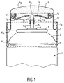
Sur ce dessin : la figure unique représente, en coupe axiale, un dispositif applicateur selon l'invention.In this drawing: the single figure represents, in section axial, an applicator device according to the invention.
En se référant au dessin, on voit que l'on a désigné par 1
le réservoir pressurisé du dispositif selon l'invention. Ce réservoir est
un bidon cylindrique de section droite circulaire, dont le sommet est
conformé en une ogive 2, qui porte, à sa partie supérieure, une
coupelle de valve solidarisée du bidon par un bourrelet de sertissage 3.
La coupelle de valve porte, selon son axe, une valve de distribution 4
qui, dans le cas de cet exemple, est une valve comportant une tige
émergente 5 ; l'ouverture de la valve 4 s'effectue par basculement
latéral de la tige émergente 5 ; la valve peut être du type commercialisé
par la société "COSTER" sous la référence "TR 120-40". Dans la zone
de jonction de l'ogive 2 avec la paroi cylindrique du réservoir 1, on a
réalisé une gorge d'encliquetage périphérique 6.Referring to the drawing, we see that we have designated by 1
the pressurized tank of the device according to the invention. This tank is
a cylindrical can of circular cross section, the top of which is
shaped like a
Dans le réservoir 1, on a conditionné sous pression un liquide à distribuer. Ce liquide peut être une composition liquide de déodorant corporel ayant une viscosité d'environ 0,003 Pa.s. La pressurisation peut être réalisée soit en mettant directement le liquide en contact avec le gaz propulseur, soit en séparant le liquide et le gaz propulseur par un piston mobile ou par une poche souple déformable, ce qui libère, dans ce dernier cas, de l'obligation d'utiliser le dispositif dans une position déterminée, soit valve en haut, soit valve en bas. Dans l'exemple décrit, on a utilisé comme gaz propulseur le butane, le liquide étant séparé du butane par un piston mobile.In tank 1, a pressure was conditioned liquid to be dispensed. This liquid can be a liquid composition of body deodorant with a viscosity of approximately 0.003 Pa.s. The pressurization can be carried out either by putting the liquid directly in contact with the propellant, either by separating the liquid and the gas propellant by a movable piston or by a flexible deformable pocket, which releases, in the latter case, from the obligation to use the device in a determined position, either valve at the top or valve at the bottom. In the example described, the propellant used was butane, liquid being separated from butane by a movable piston.
Sur le réservoir qui vient d'être décrit, on a fixé une tête
de distribution, qui comporte, d'une part, une jupe rigide 7, d'autre
part, une coupelle 8, qui constitue le support d'un dôme distributeur 9
et, enfin un élément souple 10, qui relie la coupelle 8 et la jupe rigide
7. La jupe rigide 7 comporte intérieurement, à sa base, un bourrelet
d'encliquetage annulaire 11, qui est destiné à coopérer avec la gorge
d'encliquetage 6. La jupe rigide 7 est reliée au voisinage de sa bordure
supérieure 7a à une paroi cylindrique, qui constitue l'élément souple
10, la liaison étant effectuée selon une zone arrondie 10a, dont la
convexité est tournée vers le bourrelet d'encliquetage 11. La jupe
rigide 7 et l'élément souple 10 ont une forme générale cylindrique et
constituent des cylindres coaxiaux. Le long de sa bordure, qui est
opposée à la zone 10a, l'élément souple 10 se raccorde à la coupelle 8 ;
ladite coupelle 8 comporte une dépression annulaire 8a au fond de
laquelle se trouve des saillies qui constituent des moyens d'accrochage
12 pour le dôme distributeur 9. Dans sa zone centrale, la coupelle 8 est
solidaire d'un embout 13 de forme cylindrique, ledit embout
comportant selon son axe une canalisation 14, dont la partie inférieure
14a a un diamètre élargi, ladite partie débouchant à l'extérieur par une
embouchure tronconique 14b. Dans la partie 14a de la canalisation 14,
on engage à force, sur quelques millimètres, l'extrémité libre. de la tige
émergente 5 de la valve 4 pour obtenir un raccordement étanche entre
la tige 5 et l'embout 13.On the tank which has just been described, a dispensing head has been fixed, which comprises, on the one hand, a rigid skirt 7, on the other hand, a cup 8, which constitutes the support of a dispensing
A l'intérieur de la coupelle 8, on a mis en place le dôme
distributeur 9, qui est constitué par un fritté de polyéthyléne ayant une
porosité de 40 microns. La rugosité du dôme distributeur est telle que
la moyenne Ra des écarts de rugosité est de l'ordre de 15 µm ; Ra est
la moyenne arithmétique des écarts de la surface réelle par rapport à la
surface médiane; cette moyenne arithmétique Ra est donnée par la
formule :
Pour mettre en oeuvre le dispositif ci-dessus décrit,
l'utilisateur applique la face externe 9a du dôme 9 contre la surface à
traiter, par exemple la peau d'une aisselle si le liquide conditionné dans
le réservoir 1 est un liquide déodorant. Il déplace alors latéralement le
dispositif par rapport à l'aisselle, d'où il résulte une force de friction,
qui entraíne la déformation de l'élément souple 10, et, par conséquent,
un déplacement sensiblement radial de la coupelle 8 par rapport au
réservoir 1 et donc par rapport à l'axe de la valve 4. Il s'en suit un
basculement latéral de la tige émergente 5 et donc une ouverture de la
valve 4 avec éjection simultanée du liquide conditionné sous pression
dans le réservoir 1. Le liquide arrive sur la face interne 9b du dôme
distributeur 9 ; il se répartit sur toute cette face interne et, sous l'effet
de la pression de distribution, il traverse le fritté constitutif du dôme
distributeur 9 pour venir affleurer sur la face externe 9a dudit dôme.
Le liquide est alors distribué par friction sur le support à traiter, en
l'occurrence la peau de l'aisselle ; s'il y a un excès de liquide, la force
de friction diminue, ce qui entraíne la fermeture de la valve 4 sous
l'effet du rappel élastique, qui existe à l'intérieur de ladite valve.To implement the device described above, the user applies the external surface 9a of the
On constate que le dispositif, qui vient d'être décrit, est
d'un prix de revient extrêmement réduit car, l'ensemble de la tête de
distribution constitué par la jupe 7, l'élément souple 10 et la coupelle 8
peut être réalisé en une seule pièce par moulage de matière plastique.
L'utilisation de ce dispositif est particulièrement fiable étant donné qu'il
ne peut y avoir aucune fuite. Enfin, I'agrément d'une application
topique au moyen de ce dispositif est très satisfaisant car l'utilisateur
ressent une application douce et non grasse avec un effet de fraícheur et
l'application peut être effectuée directement sans retournement
préalable du dispositif.It can be seen that the device, which has just been described, is
of an extremely reduced cost price because, the whole of the head of
distribution constituted by the skirt 7, the
Claims (22)
- Applicator device for liquid, comprising a container for the liquid to be applied to a surface to be treated, and a dispenser head (9) connected to the said container via a dispenser cap (7, 8, 10), the dispenser head (9) being made of a porous material adapted for application of the liquid by simple rubbing of the outer face (9a) of the said head (9) on the surface to be treated, the container being a pressurized reservoir (1) equipped with a dispenser valve (4), the dispenser head (9) being borne by a support which constitutes an element of the dispenser cap and is mechanically connected to a joining piece (13) capable of cooperating with the said valve (4) so as to bring about its opening under the action of a mechanical stress exerted on the dispenser head (9), the liquid discharged from the reservoir (1) during the said opening being channelled by a channel (14) through the said joining piece (13) towards that face (9b) of the dispenser head (9) which is opposite the outer face (9a) of the said head (9), the dispenser cap comprising a fastening member allowing the said cap to be connected to the reservoir (1), and the fastening member being a rigid skirt (7) fixed on the reservoir (1) by snap-fitting of a snap-fitting zone (11), characterized in that a flexible element (10) connects the said fastening member and the support of the dispenser head (9), the rigid skirt (7) being connected, in the vicinity of its upper edge (7a), to a cylindrical wall which constitutes the flexible element (10), the dispenser cap (7, 10, 8) being made in one piece by moulding of plastic material.
- Device according to Claim 1, characterized in that the porous material from which the dispenser head (9) is made is a sintered material.
- Device according to either of Claims 1 and 2, characterized in that the connection between the rigid skirt (7) and the cylindrical wall which constitutes the flexible element (10) is effected via a rounded zone (10a) whose convexity is directed towards the snap-fitting zone (11).
- Device according to one of Claims 1 to 3, characterized in that the support of the dispenser head (9) is a dish (8) exhibiting, over at least one zone, a depression (8a) capable of collecting an excess of liquid discharged via the valve (4).
- Device according to one of Claims 1 to 4, characterized in that the support of the dispenser head (9) comprises at least one fastening means (12) for holding the dispenser head (9) on the said support.
- Device according to one of Claims 1 to 5, characterized in that an obstacle is arranged opposite that end of the internal channel (14) of the joining piece (13) which does not cooperate directly with the valve (4), in order to act as a jet break.
- Device according to one of Claims 1 to 6, characterized in that substantially radial channels are formed between the inner face of the support and the inner face of the dispenser head (9).
- Device according to one of Claims 1 to 7, characterized in that the reservoir (1) is a cylindrical can whose top is shaped as a nose cone (2) and carries the dispenser valve (4), a snap-fitting groove (6) being provided in the connection zone between the cylindrical wall and the nose cone wall (2), the rigid skirt (7) being cylindrical and having, in the vicinity of one of its edges, a snap-fitting means (11) capable of cooperating with the said snap-fitting groove (6).
- Device according to Claim 8 taken together with Claim 1, characterized in that the flexible element (10) connects that zone of the rigid skirt (7) furthest from the snap-fitting zone to the periphery of the support of the dispenser head (9).
- Device according to Claim 9, characterized in that the rigid skirt (7) and the flexible element (10) consist of a continuous wall surrounding the dispenser valve (4) when the dispenser cap is snapped onto the reservoir (1).
- Device according to one of Claims 1 to 10, characterized in that the dispenser valve (4) comprises a protruding stem (5) which is inserted partially, in a sealed manner, into an internal channel (14) of the joining piece (13).
- Device according to Claim 11 characterized in that the joining piece (13) is arranged in the central zone of the support of the dispenser head (9), the said joining piece (13) having a cylindrical shape, along the axis of which its internal channel (14) is formed.
- Device according to one of Claims 1 to 12, characterized in that, with the exception of the fastening means (12) of the dispenser head (9), the dispenser cap (7, 10, 8) is a component with revolution about an axis.
- Device according to Claim 11, characterized in that the dispenser valve (4) is a valve which opens by lateral tilting of its protruding stem (5).
- Device according to one of Claims 1 to 14, characterized in that the liquid to be dispensed is a liquid with cosmetic or dermopharmaceutical action applied locally on the skin of a user.
- Device according to Claim 15, characterized in that the liquid with cosmetic or dermopharmaceutical action applied locally on the skin of a user is a deodorant.
- Device according to Claim 2, characterized in that the sintered material is obtained by compression of particles of plastic material.
- Device according to one of Claims 1 to 17, characterized in that the porosity of the material constituting the dispenser head (9) is between 10 microns and 500 microns.
- Device according to Claim 18, characterized in that the said porosity is between 10 microns and 200 microns.
- Device according to one of Claims 1 to 19, characterized in that the dispenser head (9) consists of a non-deformable material.
- Device according to one of Claims 1 to 20, characterized in that the application face of the dispenser head (9) has a surface roughness which is such that the mean Ra of the roughness spacings is between 0.5 µm and 100 µm Ra being the arithmetic mean of the spacings of the real surface in relation to the medium surface given by the formula
- Device according to Claim 21, characterized in that Ra is between 6 µm and 50 µm.
Priority Applications (1)
| Application Number | Priority Date | Filing Date | Title |
|---|---|---|---|
| EP98202441A EP0875168B1 (en) | 1993-11-29 | 1994-11-17 | Applicator device for liquids |
Applications Claiming Priority (2)
| Application Number | Priority Date | Filing Date | Title |
|---|---|---|---|
| FR9314235 | 1993-11-29 | ||
| FR9314235A FR2713060B1 (en) | 1993-11-29 | 1993-11-29 | Applicator device for liquid. |
Related Child Applications (1)
| Application Number | Title | Priority Date | Filing Date |
|---|---|---|---|
| EP98202441A Division EP0875168B1 (en) | 1993-11-29 | 1994-11-17 | Applicator device for liquids |
Publications (2)
| Publication Number | Publication Date |
|---|---|
| EP0655208A1 EP0655208A1 (en) | 1995-05-31 |
| EP0655208B1 true EP0655208B1 (en) | 1999-07-14 |
Family
ID=9453312
Family Applications (2)
| Application Number | Title | Priority Date | Filing Date |
|---|---|---|---|
| EP98202441A Expired - Lifetime EP0875168B1 (en) | 1993-11-29 | 1994-11-17 | Applicator device for liquids |
| EP94402607A Expired - Lifetime EP0655208B1 (en) | 1993-11-29 | 1994-11-17 | Applicator device for liquids |
Family Applications Before (1)
| Application Number | Title | Priority Date | Filing Date |
|---|---|---|---|
| EP98202441A Expired - Lifetime EP0875168B1 (en) | 1993-11-29 | 1994-11-17 | Applicator device for liquids |
Country Status (6)
| Country | Link |
|---|---|
| US (1) | US5567073A (en) |
| EP (2) | EP0875168B1 (en) |
| CA (1) | CA2136585C (en) |
| DE (2) | DE69419481T2 (en) |
| ES (2) | ES2196478T3 (en) |
| FR (1) | FR2713060B1 (en) |
Families Citing this family (59)
| Publication number | Priority date | Publication date | Assignee | Title |
|---|---|---|---|---|
| FR2736624B1 (en) * | 1995-07-13 | 1997-08-22 | Oreal | DEVICE FOR DISPENSING A PRODUCT STORED UNDER PRESSURE AND CONTAINER THUS EQUIPPED |
| FR2737472B1 (en) * | 1995-08-02 | 1997-09-19 | Oreal | DEVICE FOR DISPENSING AND PACKAGING A PRESSURE STORED PRODUCT |
| FR2737707B1 (en) * | 1995-08-08 | 1997-09-12 | Oreal | APPLICATION ASSEMBLY OF A FLUID OR SOLID PRODUCT |
| FR2741600B1 (en) | 1995-11-23 | 1997-12-19 | Oreal | APPLICATION ASSEMBLY OF A FLUID OR SOLID PRODUCT |
| FR2744104B1 (en) * | 1996-01-29 | 1998-03-20 | Oreal | DEVICE FOR PACKAGING, DISPENSING AND APPLYING A GEL OR FOAM |
| FR2746270B1 (en) * | 1996-03-21 | 1998-10-30 | Oreal | APPLICATION ASSEMBLY OF A FLUID OR SOLID PRODUCT |
| US6231259B1 (en) | 1996-07-26 | 2001-05-15 | The Gillette Company | Viscous product dispenser with porous dome |
| FR2755109B1 (en) * | 1996-10-25 | 1999-01-08 | Oreal | FOAM DISPENSING DEVICE |
| US6099184A (en) * | 1997-05-14 | 2000-08-08 | Painter's Products, Inc. | Dispenser-applicator assembly |
| US6048583A (en) * | 1998-01-28 | 2000-04-11 | Sunshine Sales, Inc. | Method of applying a liquid protectorant |
| NL1010774C2 (en) * | 1998-03-30 | 2000-01-28 | Wartner B V | Device for administering an amount of liquid coolant and an administering element. |
| US5989531A (en) * | 1998-11-13 | 1999-11-23 | Colgate-Palmolive Company | Antiperspirant formulation for porous applicator |
| DE19853253A1 (en) * | 1998-11-18 | 2000-05-25 | Beiersdorf Ag | Device for applying liquid media to the skin |
| US6030138A (en) | 1998-11-23 | 2000-02-29 | Colgate-Palmolive Company | Microporous applicator |
| DE19920624A1 (en) | 1999-05-05 | 2000-11-09 | Beiersdorf Ag | Device for applying viscous media |
| GB2354711B (en) * | 1999-08-10 | 2003-10-29 | Johnson & Son Inc S C | Dual function dispenser |
| US6569387B1 (en) | 1999-08-10 | 2003-05-27 | S.C. Johnson & Son, Inc. | Dual function dispenser |
| US6269821B1 (en) * | 1999-12-13 | 2001-08-07 | Joseph J. Berke | Aerosol applicator apparatus and method for health and beauty products |
| JP2001204670A (en) * | 2000-01-26 | 2001-07-31 | Taiho Ind Co Ltd | Surface treating device |
| FR2810857B1 (en) * | 2000-06-28 | 2003-01-10 | Oreal | ASSEMBLY FOR APPLYING A PRODUCT TO A SUPPORT AND USE THEREOF FOR THE TREATMENT OF HAIR |
| US6547471B1 (en) | 2000-07-20 | 2003-04-15 | The Gillette Company | Liquid applicator |
| US6485715B1 (en) | 2001-05-23 | 2002-11-26 | The Proctor & Gamble Company | Stable pressurized antiperspirant compositions containing dimethylether propellant and a low polarity solvent |
| DE10241218A1 (en) * | 2002-09-06 | 2004-03-25 | Geka Brush Gmbh | Storage and applicator unit |
| US20040086321A1 (en) * | 2002-11-01 | 2004-05-06 | Burkholz Jonathan Karl | Aerosol patient preparatory applicator |
| JP4599047B2 (en) * | 2003-09-30 | 2010-12-15 | 株式会社貝印刃物開発センター | razor |
| EP1694283A1 (en) * | 2003-11-17 | 2006-08-30 | The Procter & Gamble Company | Antiperspirant composition and applicator therefor |
| US20070086833A1 (en) * | 2005-10-19 | 2007-04-19 | Paul Gurrisi | Dispenser for personal care composition |
| FR2894941B1 (en) * | 2005-12-16 | 2008-02-01 | Cebal Sas Soc Par Actions Simp | DISTRIBUTOR APPLICATOR OF LOW VISCOUS PRODUCTS |
| EP2106272A4 (en) | 2007-01-11 | 2011-05-04 | Acrux Dds Pty Ltd | Spreading implement |
| US20080229965A1 (en) * | 2007-03-23 | 2008-09-25 | Andrew Vaughan Balash | Car wash roller |
| US8161888B2 (en) * | 2007-03-23 | 2012-04-24 | Vaughan Industries Inc. | Car wash roller and method for manufacturing the car wash roller |
| US7883287B2 (en) | 2007-05-10 | 2011-02-08 | HCT Asia, Ltd | Dispenser with thermal storage tip |
| US20090101676A1 (en) * | 2007-10-22 | 2009-04-23 | O'connell Tami | Pump Dispenser With Indented Actuator Skirt |
| CN101980629A (en) * | 2008-03-31 | 2011-02-23 | 宝洁公司 | Package for lathering a personal care product |
| FR2946965B1 (en) * | 2009-06-18 | 2015-08-07 | Airlessystems | FLUID PRODUCT DISPENSER. |
| TWM386054U (en) * | 2010-03-31 | 2010-08-11 | kun-di Huang | Cleaning device |
| BR112013000435A2 (en) | 2010-07-22 | 2016-05-17 | Colgate Palmolive Co | packaging for a consumer product |
| US9475634B2 (en) | 2010-12-01 | 2016-10-25 | Nicholas Joseph Prischak | Spray dispensing cup |
| US8393461B2 (en) | 2011-05-04 | 2013-03-12 | Vaughan Industries Inc. | Car wash roller assembly and method for manufacturing the car wash roller assembly |
| IN2014DN07474A (en) * | 2012-02-16 | 2015-04-24 | Capnia Inc | |
| US9498043B2 (en) * | 2012-03-06 | 2016-11-22 | Taiki Corp., Ltd. | Cosmetics applicator |
| USD750788S1 (en) | 2013-11-26 | 2016-03-01 | Acrux Dds Pty Ltd | Topical spreading applicator |
| USD749225S1 (en) | 2013-11-26 | 2016-02-09 | Acrux Dds Pty Ltd | Topical spreading applicator |
| CN103861201B (en) * | 2014-01-13 | 2020-01-21 | 程润昌 | Vacuum isolation storage high-pressure liquid seeping device |
| WO2015138241A1 (en) | 2014-03-10 | 2015-09-17 | Plastek Industries, Inc. | Modular spray cap |
| USD717666S1 (en) | 2014-03-14 | 2014-11-18 | The Clorox Company | Fluid dispenser |
| US10206484B2 (en) | 2016-03-16 | 2019-02-19 | HCT Group Holdings Limited | Airless cosmetics dispenser |
| FR3054108B1 (en) * | 2016-07-19 | 2020-10-02 | Chanel Parfums Beaute | COSMETIC APPLICATOR. |
| EP3487352A4 (en) | 2016-07-22 | 2020-03-25 | HCT Group Holdings Limited | Tilt action pump |
| KR20190020181A (en) | 2016-07-22 | 2019-02-27 | 에이치씨티 그룹 홀딩스 리미티드 | Downward Traction Pump Actuator |
| KR20190122220A (en) | 2017-02-17 | 2019-10-29 | 포렉스 코포레이션 | Liquid applicators and devices |
| USD841235S1 (en) | 2017-03-15 | 2019-02-19 | HCT Group Holdings Limited | Spatula cosmetic applicator |
| JP6931217B2 (en) * | 2017-03-28 | 2021-09-01 | コスメディ製薬株式会社 | Applicator for water-soluble sheet-like preparation |
| US10874193B2 (en) | 2018-03-14 | 2020-12-29 | HCT Group Holdings Limited | Wheel actuated cosmetic stick |
| USD886633S1 (en) | 2018-05-18 | 2020-06-09 | HCT Group Holdings Limited | Cosmetic dispenser with cap |
| KR102086484B1 (en) * | 2018-07-13 | 2020-03-09 | 주식회사 디티에스엠지 | Container for hair tonic |
| USD889745S1 (en) | 2018-09-06 | 2020-07-07 | HCT Group Holdings Limited | Dual purpose makeup applicator |
| USD910236S1 (en) | 2018-11-20 | 2021-02-09 | HCT Group Holdings Limited | Ball tip applicator |
| EP3714994A1 (en) | 2019-03-26 | 2020-09-30 | Sulzer Mixpac AG | Piston, cartridge, dispenser |
Family Cites Families (20)
| Publication number | Priority date | Publication date | Assignee | Title |
|---|---|---|---|---|
| US3256549A (en) * | 1964-04-01 | 1966-06-21 | Seaquist Valve Co | Applicator-scrubber |
| US3173167A (en) * | 1964-04-20 | 1965-03-16 | Kaufman Sam | Soap dispenser and applicator |
| US3345673A (en) * | 1965-10-19 | 1967-10-10 | Schwartzman Gilbert | Brush-type applicator |
| CH447061A (en) * | 1967-03-29 | 1967-11-15 | Hato Chemie Ag | Actuator on a can, the contents of which are under pressure |
| CH466176A (en) * | 1968-04-04 | 1968-11-30 | Baumann Ag | Aerosol can for foam products |
| DE2017009A1 (en) * | 1970-04-09 | 1971-10-21 | Fritz, Victor, 6500 Mainz | Applicator for containers with cleaning liquids of all kinds |
| US3663113A (en) * | 1970-08-14 | 1972-05-16 | John J Frain | Fluid applicator assembly |
| US3685913A (en) * | 1970-09-22 | 1972-08-22 | Roger D Pass | Cream and lather applicator |
| US3792802A (en) * | 1972-09-11 | 1974-02-19 | K Gores | Aerosol-can dispensing cap |
| FR2391927A2 (en) * | 1975-12-03 | 1978-12-22 | Aerosol Inventions Dev | DISTRIBUTION KIT FOR AEROSOL CONTAINER |
| US4050826A (en) * | 1976-02-11 | 1977-09-27 | Bristol-Myers Company | Liquid applicator |
| US4089609A (en) * | 1976-10-15 | 1978-05-16 | Gring Frank M | Combination applicator and closure cap means for shaving cream containers |
| US4277004A (en) * | 1979-10-15 | 1981-07-07 | Barlics John J | Cover and aerosol activator for aerosol spray can |
| DE8007391U1 (en) * | 1980-03-18 | 1982-07-22 | Lechner + Bek GmbH, 7700 Singen | Device for applying a cream-like agent to a surface |
| EP0155350B1 (en) * | 1983-09-02 | 1988-12-28 | American Cyanamid Company | Dispensing container having capillary pressure compensating valve |
| US4603992A (en) * | 1985-01-23 | 1986-08-05 | Kavoussi James P | Aerosol shaving brush |
| DE3641192A1 (en) * | 1986-12-03 | 1988-06-09 | Mitsubishi Pencil Co | WRITING OR PAINTING DEVICE |
| EP0374339B1 (en) * | 1988-12-22 | 1993-03-31 | Artebel, S.A. | Actuator for a liquid-applicator |
| FR2647034B1 (en) * | 1989-05-18 | 1991-09-06 | Oreal | APPLICATOR DEVICE FOR LIQUID, COMPRISING A DOME OF POROUS MATERIAL |
| US5230579A (en) | 1991-06-19 | 1993-07-27 | Carter-Wallace, Inc. | Porous dome applicator with push/pull cap |
-
1993
- 1993-11-29 FR FR9314235A patent/FR2713060B1/en not_active Expired - Fee Related
-
1994
- 1994-11-17 EP EP98202441A patent/EP0875168B1/en not_active Expired - Lifetime
- 1994-11-17 ES ES98202441T patent/ES2196478T3/en not_active Expired - Lifetime
- 1994-11-17 DE DE69419481T patent/DE69419481T2/en not_active Expired - Lifetime
- 1994-11-17 DE DE69432872T patent/DE69432872T2/en not_active Expired - Lifetime
- 1994-11-17 EP EP94402607A patent/EP0655208B1/en not_active Expired - Lifetime
- 1994-11-17 ES ES94402607T patent/ES2133510T3/en not_active Expired - Lifetime
- 1994-11-24 CA CA002136585A patent/CA2136585C/en not_active Expired - Lifetime
- 1994-11-28 US US08/348,983 patent/US5567073A/en not_active Expired - Lifetime
Also Published As
| Publication number | Publication date |
|---|---|
| FR2713060B1 (en) | 1996-02-02 |
| ES2133510T3 (en) | 1999-09-16 |
| DE69432872T2 (en) | 2003-12-18 |
| EP0875168A2 (en) | 1998-11-04 |
| DE69419481T2 (en) | 1999-11-18 |
| US5567073A (en) | 1996-10-22 |
| FR2713060A1 (en) | 1995-06-09 |
| CA2136585A1 (en) | 1995-05-30 |
| CA2136585C (en) | 1999-02-02 |
| EP0655208A1 (en) | 1995-05-31 |
| EP0875168A3 (en) | 2000-02-23 |
| DE69432872D1 (en) | 2003-07-31 |
| ES2196478T3 (en) | 2003-12-16 |
| EP0875168B1 (en) | 2003-06-25 |
| DE69419481D1 (en) | 1999-08-19 |
Similar Documents
| Publication | Publication Date | Title |
|---|---|---|
| EP0655208B1 (en) | Applicator device for liquids | |
| CA2171594C (en) | Applicator for product having a viscous consistency, including porous dispensing component | |
| EP0786421B1 (en) | Storage, dispensing and applying device for gel or foam | |
| EP1312280B1 (en) | Package for storing and applying a product | |
| CA1322353C (en) | Pressurized container for controlled distribution of an enhanced quality foam | |
| EP0923323B1 (en) | Dispenser for crumbly product | |
| EP1288142B1 (en) | Unit for storing and dispensing a product under pressure | |
| EP1291293A1 (en) | Valve with variable discharge and container having such valve | |
| EP0824469A1 (en) | Head and assembly for dispensing a material with a liquid to viscous consistency, comprising a flow reducer | |
| FR2769595A1 (en) | DISTRIBUTION HEAD WITH IMPROVED AIR INTAKE, AND PACKAGING AND DISTRIBUTION ASSEMBLY PROVIDED WITH SUCH A HEAD | |
| FR2774077A1 (en) | VALVE WITH OUTLET FLOW REGULATION, AND CONTAINER PROVIDED WITH SUCH A VALVE | |
| FR2777546A1 (en) | METERING TIP | |
| EP0298847B1 (en) | Container for the packaging and distribution of a product under hygienic conditions | |
| FR3004904A1 (en) | HEAD FOR DISPENSING A PRODUCT IN THE FORM OF SPRAY OR DROPPER DROP | |
| CA2218740C (en) | Applicator device for liquid | |
| EP0863089B1 (en) | Dispensing head and dispenser with such head | |
| EP1400465B1 (en) | Variable-delivery tiilt valve as well as container having such valve | |
| EP0761564B1 (en) | Device for dispensing and packaging a pressurised product | |
| EP0852210A2 (en) | Dispensing device of solid particles containing liquid | |
| EP1127802B1 (en) | Dispenser on a container | |
| FR2625730A1 (en) | DEVICE FORMING A PROTECTIVE CAP FOR A DEVICE FOR STORING AND SPRAYING PRODUCTS FOR DISTRIBUTION IN THE ATMOSPHERE, SUCH AS PERFUMES AND INSECTICIDES, AND STORAGE AND SPRAY DEVICE PROVIDED WITH SUCH A DEVICE FORMING A PROTECTIVE CAP | |
| FR2755109A1 (en) | DEVICE FOR DISTRIBUTING FOAM | |
| BE566802A (en) |
Legal Events
| Date | Code | Title | Description |
|---|---|---|---|
| PUAI | Public reference made under article 153(3) epc to a published international application that has entered the european phase |
Free format text: ORIGINAL CODE: 0009012 |
|
| 17P | Request for examination filed |
Effective date: 19941118 |
|
| AK | Designated contracting states |
Kind code of ref document: A1 Designated state(s): DE ES FR GB IT |
|
| 17Q | First examination report despatched |
Effective date: 19980313 |
|
| GRAG | Despatch of communication of intention to grant |
Free format text: ORIGINAL CODE: EPIDOS AGRA |
|
| GRAG | Despatch of communication of intention to grant |
Free format text: ORIGINAL CODE: EPIDOS AGRA |
|
| GRAH | Despatch of communication of intention to grant a patent |
Free format text: ORIGINAL CODE: EPIDOS IGRA |
|
| GRAH | Despatch of communication of intention to grant a patent |
Free format text: ORIGINAL CODE: EPIDOS IGRA |
|
| GRAA | (expected) grant |
Free format text: ORIGINAL CODE: 0009210 |
|
| AK | Designated contracting states |
Kind code of ref document: B1 Designated state(s): DE ES FR GB IT |
|
| GBT | Gb: translation of ep patent filed (gb section 77(6)(a)/1977) |
Effective date: 19990714 |
|
| REF | Corresponds to: |
Ref document number: 69419481 Country of ref document: DE Date of ref document: 19990819 |
|
| REG | Reference to a national code |
Ref country code: ES Ref legal event code: FG2A Ref document number: 2133510 Country of ref document: ES Kind code of ref document: T3 |
|
| PLBE | No opposition filed within time limit |
Free format text: ORIGINAL CODE: 0009261 |
|
| STAA | Information on the status of an ep patent application or granted ep patent |
Free format text: STATUS: NO OPPOSITION FILED WITHIN TIME LIMIT |
|
| 26N | No opposition filed | ||
| REG | Reference to a national code |
Ref country code: GB Ref legal event code: IF02 |
|
| PGFP | Annual fee paid to national office [announced via postgrant information from national office to epo] |
Ref country code: GB Payment date: 20131113 Year of fee payment: 20 Ref country code: FR Payment date: 20131108 Year of fee payment: 20 Ref country code: DE Payment date: 20131113 Year of fee payment: 20 |
|
| PGFP | Annual fee paid to national office [announced via postgrant information from national office to epo] |
Ref country code: IT Payment date: 20131112 Year of fee payment: 20 Ref country code: ES Payment date: 20131011 Year of fee payment: 20 |
|
| REG | Reference to a national code |
Ref country code: DE Ref legal event code: R071 Ref document number: 69419481 Country of ref document: DE |
|
| REG | Reference to a national code |
Ref country code: GB Ref legal event code: PE20 Expiry date: 20141116 |
|
| REG | Reference to a national code |
Ref country code: ES Ref legal event code: FD2A Effective date: 20150126 |
|
| PG25 | Lapsed in a contracting state [announced via postgrant information from national office to epo] |
Ref country code: GB Free format text: LAPSE BECAUSE OF EXPIRATION OF PROTECTION Effective date: 20141116 |
|
| PG25 | Lapsed in a contracting state [announced via postgrant information from national office to epo] |
Ref country code: ES Free format text: LAPSE BECAUSE OF EXPIRATION OF PROTECTION Effective date: 20141118 |