EP0655155B1 - Device for securing an electronic display unit - Google Patents
Device for securing an electronic display unit Download PDFInfo
- Publication number
- EP0655155B1 EP0655155B1 EP94918906A EP94918906A EP0655155B1 EP 0655155 B1 EP0655155 B1 EP 0655155B1 EP 94918906 A EP94918906 A EP 94918906A EP 94918906 A EP94918906 A EP 94918906A EP 0655155 B1 EP0655155 B1 EP 0655155B1
- Authority
- EP
- European Patent Office
- Prior art keywords
- rail
- housing
- intermediate part
- projection
- designed
- Prior art date
- Legal status (The legal status is an assumption and is not a legal conclusion. Google has not performed a legal analysis and makes no representation as to the accuracy of the status listed.)
- Expired - Lifetime
Links
Images

Classifications
-
- G—PHYSICS
- G09—EDUCATION; CRYPTOGRAPHY; DISPLAY; ADVERTISING; SEALS
- G09F—DISPLAYING; ADVERTISING; SIGNS; LABELS OR NAME-PLATES; SEALS
- G09F3/00—Labels, tag tickets, or similar identification or indication means; Seals; Postage or like stamps
- G09F3/08—Fastening or securing by means not forming part of the material of the label itself
- G09F3/18—Casings, frames or enclosures for labels
- G09F3/20—Casings, frames or enclosures for labels for adjustable, removable, or interchangeable labels
- G09F3/204—Casings, frames or enclosures for labels for adjustable, removable, or interchangeable labels specially adapted to be attached to a shelf or the like
-
- G—PHYSICS
- G09—EDUCATION; CRYPTOGRAPHY; DISPLAY; ADVERTISING; SEALS
- G09F—DISPLAYING; ADVERTISING; SIGNS; LABELS OR NAME-PLATES; SEALS
- G09F3/00—Labels, tag tickets, or similar identification or indication means; Seals; Postage or like stamps
- G09F3/08—Fastening or securing by means not forming part of the material of the label itself
- G09F3/18—Casings, frames or enclosures for labels
- G09F3/20—Casings, frames or enclosures for labels for adjustable, removable, or interchangeable labels
- G09F3/208—Electronic labels, Labels integrating electronic displays
Definitions
- the present invention relates to a device for fixing housings of electronic modules allowing the display of information, such as prices or the like, in retail stores or any other site, such as for example storage areas. or production factories.
- This installation makes it possible to replace conventional cardboard labels, with liquid crystal display modules which receive their display instructions from a management unit which centralizes all the information relating to the various products exhibited in the same store.
- An important advantage of such an installation is that it makes it possible to avoid the long manipulations that a complete updating of the prices of the various items exhibited in a store requires, such as a large area.
- These display modules are intended to take place along the edges of the shelves of the shelves in which the articles are placed.
- the means for fixing the modules' housings consist of rails which run along the shelving boards and which include slides in which complementary grooves are fitted which are presented by said housings.
- the boxes are manually translated into these rails until they are positioned at the level of the articles to which they correspond.
- a main object of the invention is therefore to propose a fixing device which makes it possible to solve this problem.
- Document GB-2 249 854 already discloses a device for fixing at least one electronic module box for displaying information relating to a product displayed in a store, in particular a retail store, comprising a rail intended to receive the housing and an intermediate piece which carries at least one elastic locking element having at least one projection intended to cooperate with a groove that the rail presents to ensure the maintenance of said housing relative to said rail, the housing and this intermediate piece having additional means for fixing said housing to said part.
- the invention aims to overcome these drawbacks.
- the solution according to the invention consists in particular in that the locking element carries a hook intended to cooperate with a complementary relief of the intermediate piece to maintain said locking element in a retracted position, by opposing its elastic stress, and where the projection is then disengaged relative to the groove of the rail with which it cooperates, the intermediate piece having an elastic branch which, when the housing and the intermediate piece are placed on the rail, is pushed back, by contact with the bottom of said rail, on the hook so as to disengage the latter from the complementary relief with which it cooperates, the locking element then elastically pushing the projection in the groove of the rail.
- the operator has only to arm the locking element, then to exert a simple pushing force on the box once the latter and its intermediate part presented on the rail .
- the fixing device proposed by the invention also has the advantage of being adaptable to shelves of shelves of different dimensions, and in particular to shelves of different thicknesses.
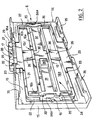
- the device shown in Figure 1 allows the attachment to a shelving board 2, a housing 1 of a display module forming an electronic label.
- This module has a screen 3 which, when the housing 1 is fixed on the board 2, is parallel to the edge 4 of the board 2 and is visible to a consumer passing between the shelves.
- This display module is part of an installation of the type which has been described in the above-mentioned French patent application FR-2,658,645.
- the fixing device mainly comprises a retaining profile 5 and a part 6 intermediate between this profile 5 and the housing 1.
- the retaining profile 5 is a part constituted by a shelf 10 for supporting said profile 5 on a shelving board and by a receiving rail 5a which has mainly a U-shaped section.
- This rail 5a has a bottom 7, bordered longitudinally by two sides 8 and 9 which are designated throughout the text by lower side 8 and upper side 9, with reference to their respective positions when the profile 5 is in place on the shelving board 2.
- the tablet 10 runs along said rail 5a, extending from the bottom 7 perpendicularly to the latter, on the side opposite to the upper edge 9.
- This retaining profile 5 is intended to be mounted on the shelving board 2 so that the shelf 10 and the bottom 7 are respectively in abutment on the upper surface of the board 2 and on the edge 4.
- the fixing of the profile 5 on the board 2 is carried out by riveting.
- the faces of the shelf 10 and the bottom 7 which are opposite their bearing faces have longitudinal grooves 11 intended to receive and conceal the heads of the rivets (not shown).
- the lower side 8 is conventionally provided with a flat groove 12 of C-shaped section, which is open on the face of this side 8 which is opposite to the upper side 9.
- This groove 12 thus forms a slide which, when the profile 5 is in place, is open at the bottom and can carry, for example, a support made of folded PVC material for advertising elements (of the type commonly called STOP-RAYON).
- the rail 5a also has two grooved longitudinal inner grooves, referenced by 13, which are carried one by the lower edge 8, the other by the upper edge 9. These two grooved grooves 13 extend opposite one of the other over the entire length of the rail 5a, and are located in the immediate vicinity of the bottom 7.
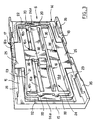
- the intermediate part 6 which is shown there is constituted by a plate 14 and an elastic locking element 21, which will be described later in more detail.
- the plate 14 is of rectangular outline. It has a bottom 14a and external 15 and internal 16 patterns in excess thickness between which is intended to come to fit the element 21.
- the external width of the plate 14 is slightly less than the distance between the opposite faces of the sides 8 and 9. Its length is substantially that of a housing 1.
- the external pattern 15 surrounds the frame 14 over a major part of its outline. It is interrupted along each of the length sides of the frame 14 by an opening 17 centered on the side to which it corresponds and extending over substantially a third on this side (proportion which is of course given only for information and may vary). On either side of this opening 17, the pattern 15 is reinforced and extends in particular from the side of the frame 14 over a thickness greater than along the widths of said frame 14.
- the parts of the outer pattern 15 which extend along the length sides of the plate 14 carry two flanges 18 which extend respectively along each of these sides, perpendicular to the bottom 14a of the plate 14. Each of these two flanges 18 carries ribs 35 in projecting towards the inside of the frame, which are intended to engage in corresponding grooves that the housing 1 presents, to hold said housing 1 relative to the intermediate element 6.
- the internal pattern 16 comprises an elongated rectangular rib 16a, the length sides of which are parallel to the length sides of the plate 14, this rib 16a being centered on the center of this plate 14.
- the widths of this rectangular rib 16a are extended by each side of the lengths of said rib by ribs 16b which stop opposite the reinforced portions of the outer pattern 15.
- the space between the outer pattern 15 and such a rib 16b is the same for each of these four ribs 16b.
- Four rounded protrusions 20 projecting from the widths of the rectangular rib 16a extend the lengths of this rib 16a beyond said widths.
- One of the lengths of the rectangular rib 16a is interrupted in its middle part by an opening 16c.
- the bottom of the frame 14 still carries two studs 19 (Figure 2) of a height less than the height of the patterns 15 and 16. These two studs 19 are disposed at each end of the longitudinal central axis of the frame 14 and are juxtaposed to the portions of pattern 15 which extend the along the widths of the frame 14. The space between each of these studs 19 and the rectangular rib 16a is substantially identical to the space between the ribs 16b and the pattern 15.
- the elastic locking element 21 has two uprights 22 connecting together two longitudinal crosspieces 23. These uprights 22 and these crosspieces 23 together define a frame 24 which fits between the patterns 15 and 16 and which is held by friction with respect to those -this.
- the ends of the ribs 16b are located at the interior walls of the corners of the frame 24, the walls delimiting the exterior corners of the frame 24 being in contact with the reinforced portions of the external pattern 15 in excess thickness.
- the uprights 22 are then in contact through their internal walls with the rounded protrusions 20.
- Each upright 22 carries a plate 24a forming an ear which extends from this upright towards the outside of the frame.
- a plate 24a forming an ear comes to bear on one of the studs 19 when the element 21 is in place on the plate 14.
- Each longitudinal cross member 23 carries a tab 25 and a tongue 26 which are each flat and parallel to the median plane of the frame 24.
- a tab 25 extends from the cross member 23 which carries it towards the outside of the frame 24.
- a tongue 26 extends from its cross member 23 towards the inside of the frame 24. Such tab 25 and tongue 26 are centered with respect to the length of the cross member 23 which carries them.
- a tab 25 extends over a third of the length of the crosspiece 23 which carries it. It has on its edge furthest from the cross member 23 which carries the grooves 27 which are intended to cooperate, as will be described later in more detail, with the grooves of the grooves 13. On a central portion of such a tab 25, these grooves are delimited by an inclined face 28 which extends from the crests of the grooves 27 towards the crosspiece 23 which carries this tab 25, from one of the faces of the tab 25 towards the other of its faces.
- the grooves 27 on either side of this inclined face 28 are closed on one side, by a flat wall 29 which extends the face of the tab 25 which is opposite to the side of the tab 25 where the crests of the grooves of the pan 28.
- the flange 18 which is closest to the opening 16c also has an inclined flap 18a which is intended to extend the flap 28 of the tab 25 which is located to the right of this flange 18, when the longitudinal cross member 23 which carries this tab 25 is not stressed in bending.
- the tongue 26 carried by the longitudinal cross member 23 furthest from the opening 16c is a spacer which comes to bear on the rectangular rib 16a. It prevents this longitudinal cross member 23 from being stressed in bending.
- the other tab 26 ends with a hook 30 facing the bottom 14a and intended to come to cooperate with the edge of the opening 16c.
- the outline which is delimited on the bottom 14a by the rectangular rib 16a is hollowed out.
- the widths of the rectangular rib 16a carry, at the level of the recess thus defined, two flat elastic branches referenced by 31 and 32. They extend one and the other parallel to the sides of the lengths of the bottom 14, respectively d 'one of the widths of the rib 16a up to substantially the center of the latter.
- the branch 31 ends at its end furthest from the width side which carries it by two lugs 33 and 34 which project in relation to said branch, respectively on the side of the latter intended to be opposite the bottom 7 and on the side thereof intended to be in look at the bottom of the housing 1.
- the lug 33 is less tall than the lug 34.
- the housing 1 has on its bottom a recess (not shown), intended to receive the lug 34, as well as an inclined groove 37 (Figure 1) intended to guide the lug 34 to this recess.
- the branch 32 ends in turn with a plate 36 which is slightly projecting with respect to the face of the bottom 14 intended to be opposite the bottom 7 and which is located exactly in line with the area occupied by the hook 30 when the tongue 26 which is terminated by this hook 30 is pushed back through the opening 16c.
- an operator places the retaining profile 5 on the shelving board 2 and fixes it thereon, for example by riveting the bottom 7 and the shelf 10 on the edge 4 and the upper face of the board 2 who have undergone a pre-drilling.
- the rivets are regularly distributed along the length of the board 2 and are arranged so that their heads are at the level of the grooves 11.
- the profile 5 can be mounted on shelving boards of different dimensions, and in particular of different thickness.
- the elastic locking element 21 is placed on the plate 14 as follows: the frame 24 is presented with a slight inclination relative to the plate 14, so as to fit one of the legs 25 into the opening 18 which is closest to that of the lengths of the rectangular rib 16a which has no opening. Then the frame 21 is folded down between the exterior and interior patterns 15 and 16, by bending the crosspiece 23 which carries the other tab 25, so as to introduce the latter into the opening 18 which matches ( Figure 2).
- the housing 1 is then slid along the intermediate element 6, between the flanges 18, so that the ribs 35 engage in the complementary grooves that the housing 1 has.
- the groove 37 guides the lug 34 to the recess that the housing has for receiving it.
- the lug 33 of the tongue 31 is pushed back by contact with the bottom 7, so that the lug 34 is forced into the recess that has the housing 1.
- the housing 1 is thus locked relative to the intermediate piece 6.
- the operator has a tool which allows him to interpose a blade between the grooves of the upper tab 25 and the grooves of the groove upper 13 of the holding profile.
- the wall 29 and the inclined face 28 are used to guide the blade to the crest of the grooves 27 of the tab 25.
- the operator disengages these grooves from the upper grooves of the holding profile. 5. It can then remove from the rail 5a the assembly that constitutes the intermediate piece 6 and the housing 1.
- the lug 34 is no longer locked in the corresponding recess in the bottom of the housing 1.
- the operator slides the housing 1 with respect to the intermediate piece 6.
- the various parts of the device which has just been described are produced by molding, for example PVC.
- the bottom of one or other of the two grooves 13 can be made of a more flexible material (rubber, flexible PVC or other material) than the rest of the profile 5 and into which the grooves 27 penetrate to take hold .
- a profile 5 is obtained by using coextrusion methods known to those skilled in the art. This softer material can be placed on or in place of the teeth. It can fill the throat, be laminated or fluted.
- Profile 5 intermediate piece 6 and housing can be personalized by particular colors, by varying the colors of the materials in which these three elements are made, or by plating on the bottom 7 of the rail 5a a colored strip.
- the teeth of the rail can be produced separately.
- the teeth of the rail can be replaced by foam, rubber or any other fastening material fulfilling the blocking function of the intermediate piece.
- the teeth of the intermediate piece can themselves be replaced by any other locking means. They can in particular, either in the upper part, in the lower part, or both, be made of a plastic material different from that of the rest of the intermediate piece. This biplasticity can be achieved by adding an additional part.
- grooves at the bottom of the rail may have another arrangement and, in particular, be located for example between the lower and upper edges of the rail, or even at the front of the rail.
- the shape of the support profile can be very variable. In the example described, the shape of the profile allows it to be adapted on a board with a vertical edge. Its shape could be different for basket wire or glass supports (glass shelf, for example).
- the fixing of the profile on its support can be achieved by other means than by riveting and in particular by gluing or by adhesive tapes.
Abstract
Description
La présente invention est relative à un dispositif pour la fixation de boîtiers de modules électroniques permettant l'affichage d'informations, telles que des prix ou analogues, dans les magasins de vente au détail ou tout autre site, comme par exemple des aires de stockage ou des usines de production.The present invention relates to a device for fixing housings of electronic modules allowing the display of information, such as prices or the like, in retail stores or any other site, such as for example storage areas. or production factories.
La Demanderesse a récemment proposé, notamment dans sa demande de brevet français FR-2.658.645, une installation comportant une pluralité de modules d'affichage qui constituent des étiquettes électroniques commandables à distance.The Applicant has recently proposed, in particular in its French patent application FR-2,658,645, an installation comprising a plurality of display modules which constitute remotely controllable electronic labels.
Cette installation permet de remplacer les étiquettes cartonnées classiques, par des modules d'affichage à écran à cristaux liquides qui reçoivent leurs instructions d'affichage d'une unité de gestion qui centralise toutes les informations relatives aux différents produits exposés dans un même magasin.This installation makes it possible to replace conventional cardboard labels, with liquid crystal display modules which receive their display instructions from a management unit which centralizes all the information relating to the various products exhibited in the same store.
Un avantage important d'une telle installation tient en ce qu'elle permet d'éviter les longues manipulations que nécessite une mise à jour complète des prix des différents articles exposés dans un magasin, tel qu'une grande surface.An important advantage of such an installation is that it makes it possible to avoid the long manipulations that a complete updating of the prices of the various items exhibited in a store requires, such as a large area.
Ces modules d'affichage sont destinés à prendre place le long des tranches des planches des rayonnages dans lesquels sont placés les articles. A ce jour, les moyens de fixation des boîtiers des modules consistent en des rails qui courent le long des planches de rayonnage et qui comportent des glissières dans lesquelles on enfile des rainures complémentaires que présentent lesdits boîtiers. Les boîtiers sont translatés manuellement dans ces rails jusqu'à ce qu'ils soient positionnés au niveau des articles auxquels ils correspondent.These display modules are intended to take place along the edges of the shelves of the shelves in which the articles are placed. To date, the means for fixing the modules' housings consist of rails which run along the shelving boards and which include slides in which complementary grooves are fitted which are presented by said housings. The boxes are manually translated into these rails until they are positioned at the level of the articles to which they correspond.
Ces moyens de fixation sont néanmoins peu satisfaisants.These fixing means are nevertheless unsatisfactory.
La mise en place des boîtiers nécessite en effet que ceux-ci soient rentrer les uns derrière les autres, dans l'ordre exact dans lequel ils doivent se succéder le long du rayonnage, à partir d'une extrémité du rail qui les porte.The installation of the boxes in fact requires that they be returned one behind the other, in the exact order in which they must succeed one another along the shelving, from one end of the rail which carries them.
En outre, si l'un des modules d'affichage est à changer, il est nécessaire de désengager du rail qui le porte tous les boîtiers qui se trouvent sur le rail d'un côté ou de l'autre du boîtier du module à changer.In addition, if one of the display modules is to be changed, it is necessary to disengage from the rail which carries it all the housings which are on the rail on one side or the other of the casing of the module to be changed. .
Un but principal de l'invention est donc de proposer un dispositif de fixation qui permet de résoudre ce problème.A main object of the invention is therefore to propose a fixing device which makes it possible to solve this problem.
On connaît déjà par le document GB-2 249 854 un dispositif pour la fixation d'au moins un boîtier de module électronique pour l'affichage d'informations relatives à un produit exposé dans un magasin notamment de vente au détail, comportant un rail destiné à recevoir le boîtier et une pièce intermédiaire qui porte au moins un élément de verrouillage élastique présentant au moins une saillie destinée à coopérer avec une rainure que présente le rail pour assurer le maintien dudit boîtier par rapport audit rail, le boîtier et cette pièce intermédiaire présentant des moyens complémentaires pour la fixation dudit boîtier sur ladite pièce.Document GB-2 249 854 already discloses a device for fixing at least one electronic module box for displaying information relating to a product displayed in a store, in particular a retail store, comprising a rail intended to receive the housing and an intermediate piece which carries at least one elastic locking element having at least one projection intended to cooperate with a groove that the rail presents to ensure the maintenance of said housing relative to said rail, the housing and this intermediate piece having additional means for fixing said housing to said part.
Les différentes variantes décrites dans ce document ne sont pas d'une manipulation aisée. En particulier, le montage de la pièce intermédiaire sur le rail nécessite des mouvements relativement précis au niveau du rail de la part de l'opérateur, ce qui est mal commode.The different variants described in this document are not easy to handle. In particular, the mounting of the intermediate piece on the rail requires relatively precise movements at the level of the rail on the part of the operator, which is inconvenient.
Les opérations de montage s'avèrent en outre longues.The assembly operations also prove to be long.
Egalement, le maintien ainsi réalisé n'est pas d'une grande fiabilité.Also, the maintenance thus produced is not very reliable.
L'invention a pour but de pallier ces inconvénients.The invention aims to overcome these drawbacks.
La solution selon l'invention consiste notamment en ce que l'élément de verrouillage porte un crochet destiné à coopérer avec un relief complémentaire de la pièce intermédiaire pour maintenir ledit élément de verrouillage dans une position escamotée, en s'opposant à sa sollicitation élastique, et où la saillie étant alors désengagée par rapport à la rainure du rail avec laquelle elle coopère, la pièce intermédiaire présentant une branche élastique qui, lors de la mise en place du boîtier et de la pièce intermédiaire sur le rail, est repoussée, par contact avec le fond dudit rail, sur le crochet de façon à désengager celui-ci du relief complémentaire avec lequel il coopère, l'élément de verrouillage repoussant alors élastiquement la saillie dans la rainure du rail.The solution according to the invention consists in particular in that the locking element carries a hook intended to cooperate with a complementary relief of the intermediate piece to maintain said locking element in a retracted position, by opposing its elastic stress, and where the projection is then disengaged relative to the groove of the rail with which it cooperates, the intermediate piece having an elastic branch which, when the housing and the intermediate piece are placed on the rail, is pushed back, by contact with the bottom of said rail, on the hook so as to disengage the latter from the complementary relief with which it cooperates, the locking element then elastically pushing the projection in the groove of the rail.
Ainsi, pour fixer le boîtier sur le rail, l'opérateur n'a qu'à armer l'élément de verrouillage, puis à exercer un simple effort de poussée sur le boîtier une fois celui-ci et sa pièce intermédiaire présentés sur le rail.Thus, to fix the box on the rail, the operator has only to arm the locking element, then to exert a simple pushing force on the box once the latter and its intermediate part presented on the rail .
Le dispositif de fixation proposé par l'invention présente également l'avantage d'être adaptable à des tablettes de rayonnages de différentes dimensions, et notamment à des tablettes d'épaisseurs différentes.The fixing device proposed by the invention also has the advantage of being adaptable to shelves of shelves of different dimensions, and in particular to shelves of different thicknesses.
D'autres caractéristiques et avantages de l'invention ressortiront encore de la description qui suit d'un mode de réalisation particulier de celle-ci. Cette description doit être lue en regard des dessins annexés sur lesquels :
- la figure 1 est une vue en perspective d'un dispositif conforme à l'invention pour la fixation du boîtier d'un module d'affichage électronique ;
- la figure 2 et la figure 3 sont des vues en perspective de la pièce intermédiaire de verrouillage du dispositif de fixation de la figure 1, cette pièce intermédiaire étant représentée respectivement dans son état de verrouillage et dans son état de déverrouillage.
- Figure 1 is a perspective view of a device according to the invention for fixing the housing of an electronic display module;
- Figure 2 and Figure 3 are perspective views of the intermediate locking piece of the fixing device of Figure 1, this intermediate piece being shown respectively in its locked state and in its unlocked state.
Le dispositif représenté sur la figure 1, permet la fixation sur une planche 2 de rayonnage, d'un boîtier 1 d'un module d'affichage formant étiquette électronique. Ce module présente un écran 3 qui, lorsque le boîtier 1 est fixé sur la planche 2, est parallèle à la tranche 4 de la planche 2 et est visible par un consommateur passant entre les rayonnages.The device shown in Figure 1, allows the attachment to a
Ce module d'affichage fait partie d'une installation du type de celle qui a été décrite dans la demande de brevet français FR-2.658.645 précitée.This display module is part of an installation of the type which has been described in the above-mentioned French patent application FR-2,658,645.
Le dispositif de fixation comporte principalement un profil de maintien 5 et une pièce 6 intermédiaire entre ce profil 5 et le boîtier 1.The fixing device mainly comprises a
Le profil de maintien 5 est une pièce constituée par une tablette 10 pour le support dudit profil 5 sur une planche de rayonnage et par un rail de réception 5a qui a principalement une section en forme de U. Ce rail 5a présente un fond 7, bordé longitudinalement par deux flancs 8 et 9 que l'on désigne dans toute la suite du texte par flanc inférieur 8 et flanc supérieur 9, en référence à leurs positions respectives lorsque le profil 5 est en place sur la planche 2 de rayonnage. La tablette 10 court le long dudit rail 5a en s'étendant à partir du fond 7 perpendiculairement à celui-ci, du côté opposé au bord supérieur 9.The
Ce profil de maintien 5 est destiné à être monté sur la planche de rayonnage 2 de façon que la tablette 10 et le fond 7 soient respectivement en appui sur la surface supérieure de la planche 2 et sur la tranche 4. La fixation du profil 5 sur la planche 2 est réalisée par rivetage. Les faces de la tablette 10 et du fond 7 qui sont opposées à leurs faces d'appui présentent des gorges longitudinales 11 destinées à recevoir et dissimuler les têtes des rivets (non représentés).This retaining
Le flanc inférieur 8 est classiquement muni d'une rainure plate 12 de section en forme de C, qui est ouverte sur la face de ce flanc 8 qui est opposée au flanc supérieur 9. Cette rainure 12 forme ainsi une glissière qui, lorsque le profil 5 est en place, est ouverte vers le bas et peut porter, par exemple, un support en matériau PVC plié pour éléments de publicité (du type couramment dénommés STOP-RAYON).The
Le rail 5a présente encore deux gorges intérieures longitudinales cannelées, référencées par 13, qui sont portées l'une par le bord inférieur 8, l'autre par le bord supérieur 9. Ces deux rainures cannelées 13 s'étendent en regard l'une de l'autre sur toute la longueur du rail 5a, et sont situées au voisinage immédiat du fond 7.The
On se réfère maintenant plus particulièrement aux figures 2 et 3.Reference is now made more particularly to FIGS. 2 and 3.
La pièce intermédiaire 6 qui y est représentée est constituée par une plaque 14 et un élément 21 de verrouillage élastique, qui sera décrit plus loin plus en détails. La plaque 14 est de contour rectangulaire. Elle comporte un fond 14a et des motifs extérieur 15 et intérieur 16 en surépaisseur entre lesquels est destiné à venir s'emboîter l'élément 21. La largeur extérieure de la plaque 14 est légèrement inférieure à la distance entre les faces en regard des flancs 8 et 9. Sa longueur est sensiblement celle d'un boîtier 1.The
Le motif extérieur 15 entoure le cadre 14 sur une majeure partie de son contour. Il est interrompu le long de chacun des côtés de longueurs du cadre 14 par une ouverture 17 centrée sur le côté auquel elle correspond et s'étendant sur sensiblement un tiers de ce côté (proportion qui n'est bien entendu donnée qu'à titre indicatif et peut varier). De part et d'autre de cette ouverture 17, le motif 15 est renforcé et s'étend en particulier à partir du flanc du cadre 14 sur une épaisseur plus importante que le long des largeurs dudit cadre 14. Les parties du motif extérieur 15 qui s'étendent le long des côtés de longueurs de la plaque 14 portent deux rebords 18 qui s'étendent respectivement le long de chacun de ces côtés, perpendiculairement au fond 14a de la plaque 14. Chacun de ces deux rebords 18 porte des nervures 35 en saillie vers l'intérieur du cadre, qui sont destinées à s'engager dans des rainures correspondantes que présente le boîtier 1, pour maintenir ledit boîtier 1 par rapport à l'élément intermédiaire 6.The
Le motif intérieur 16 comprend une nervure rectangulaire allongée 16a, dont les côtés de longueurs sont parallèles aux côtés de longueurs de la plaque 14, cette nervure 16a étant centrée sur le centre de cette plaque 14. Les largeurs de cette nervure rectangulaire 16a sont prolongées de chaque côté des longueurs de ladite nervure par des nervures 16b qui s'arrêtent en regard des portions renforcées du motif extérieur 15. L'espace entre le motif extérieur 15 et une telle nervure 16b est le même pour chacune de ces quatre nervures 16b. Quatre protubérances arrondies 20 formant saillie par rapport aux largeurs de la nervure rectangulaire 16a prolongent les longueurs de cette nervure 16a au-delà desdites largeurs. L'une des longueurs de la nervure rectangulaire 16a est interrompue en sa partie médiane par une ouverture 16c.The
Le fond du cadre 14 porte encore deux plots 19 (Figure 2) d'une hauteur inférieure à la hauteur des motifs 15 et 16. Ces deux plots 19 sont disposés à chacune des extrémités de l'axe médian longitudinal du cadre 14 et sont juxtaposés aux portions du motif 15 qui s'étendent le long des largeurs du cadre 14. L'espace entre chacun de ces plots 19 et la nervure rectangulaire 16a est sensiblement identique à l'espace entre les nervures 16b et le motif 15.The bottom of the
L'élément de verrouillage élastique 21 présente deux montants 22 reliant ensemble deux traverses longitudinales 23. Ces montants 22 et ces traverses 23 définissent ensemble un cadre 24 qui s'emboîte entre les motifs 15 et 16 et qui est maintenu par frottement par rapport à ceux-ci. En particulier, lorsque cet élément 21 est en place sur la plaque 14, les extrémités des nervures 16b se trouvent au niveau des parois intérieures des coins du cadre 24, les parois délimitant les coins extérieurs du cadre 24 étant quant à elles en contact avec les portions renforcées du motif extérieur 15 en surépaisseur. Les montants 22 sont alors en contact par leurs parois intérieures avec les protubérances arrondies 20.The
Chaque montant 22 porte un plateau 24a formant oreille qui s'étend de ce montant vers l'extérieur du cadre. Un tel plateau 24a formant oreille vient en appui sur l'un des plots 19 lorsque l'élément 21 est en place sur la plaque 14.Each upright 22 carries a
Chaque traverse longitudinale 23 porte une patte 25 et une languette 26 qui sont chacune plates et parallèles au plan médian du cadre 24. Une patte 25 s'étend à partir de la traverse 23 qui la porte vers l'extérieur du cadre 24. Une languette 26 s'étend à partir de sa traverse 23 vers l'intérieur du cadre 24. De telles patte 25 et languette 26 sont centrées par rapport à la longueur de la traverse 23 qui les porte.Each
Une patte 25 s'étend sur un tiers de la longueur de la traverse 23 qui la porte. Elle présente sur sa tranche la plus éloignée de la traverse 23 qui la porte des cannelures 27 qui sont destinées à coopérer, ainsi que cela sera décrit plus loin plus en détails, avec les cannelures des rainures 13. Sur une portion centrale d'une telle patte 25, ces cannelures sont délimitées par un pan incliné 28 qui s'étend des crêtes des cannelures 27 vers la traverse 23 qui porte cette patte 25, à partir d'une des faces de la patte 25 vers l'autre de ses faces. Les cannelures 27 de part et d'autre de ce pan incliné 28 sont fermées sur un côté, par une paroi plate 29 qui prolonge la face de la patte 25 qui est opposée au côté de la patte 25 où se trouvent les crêtes des cannelures du pan 28. Le rebord 18 qui est le plus proche de l'ouverture 16c présente également un pan incliné 18a qui est destiné à prolonger le pan 28 de la patte 25 qui se trouve au droit de ce rebord 18, lorsque la traverse longitudinale 23 qui porte cette patte 25 n'est pas sollicitée en flexion.A
La languette 26 portée par la traverse longitudinale 23 la plus éloignée de l'ouverture 16c est une entretoise qui vient en appui sur la nervure rectangulaire 16a. Elle empêche que cette traverse longitudinale 23 ne soit sollicitée en flexion.The
L'autre languette 26 se termine par un crochet 30 tourné vers le fond 14a et destiné à venir coopérer avec le bord de l'ouverture 16c.The
Le contour qui est délimité sur le fond 14a par la nervure rectangulaire 16a est évidé. Les largeurs de la nervure rectangulaire 16a portent, au droit de l'évidement ainsi défini, deux branches élastiques plates référencées par 31 et 32. Elles s'étendent l'une et l'autre parallèlement aux côtés de longueurs du fond 14, respectivement d'une des largeurs de la nervure 16a jusque sensiblement le centre de celle-ci. La branche 31 se termine à son extrémité la plus éloignée du côté de largeur qui la porte par deux ergots 33 et 34 qui s'étendent en saillie par rapport à ladite branche, respectivement du côté de celle-ci destiné à être en regard du fond 7 et du côté de celle-ci destiné à être en regard du fond du boîtier 1. L'ergot 33 est d'une hauteur moins importante que l'ergot 34.The outline which is delimited on the bottom 14a by the
Le boîtier 1 présente sur son fond un évidement (non représenté), destiné à recevoir l'ergot 34, ainsi qu'une gorge 37 inclinée (Figure 1) destinée à guider l'ergot 34 jusqu'à cet évidement.The housing 1 has on its bottom a recess (not shown), intended to receive the
La branche 32 se termine quant à elle par un plateau 36 qui est légèrement en saillie par rapport à la face du fond 14 destinée à être en regard du fond 7 et qui se trouve disposée exactement au droit de la zone occupée par le crochet 30 lorsque la languette 26 qui est terminée par ce crochet 30 est repoussée à travers l'ouverture 16c.The
On va maintenant décrire une mise en oeuvre de ce dispositif de fixation.We will now describe an implementation of this fixing device.
Dans un premier temps, un opérateur pose le profil de maintien 5 sur la planche 2 de rayonnage et le fixe sur celle-ci par exemple par rivetage du fond 7 et de la tablette 10 sur la tranche 4 et la face supérieure de la planche 2 qui ont subi un pré-perçage. Les rivets sont répartis régulièrement dans la longueur de la planche 2 et sont disposés de façon que leurs têtes se trouvent au niveau des rainures 11.First, an operator places the retaining
Comme on l'aura noté, le profil 5 peut être monté sur des planches de rayonnage de différentes dimensions, et notamment d'épaisseur différente.As will have been noted, the
L'élément de verrouillage élastique 21 est mis en place sur la plaque 14 de la façon suivante : l'on présente le cadre 24 avec une légère inclinaison par rapport à la plaque 14, de façon à emboîter l'une des pattes 25 dans l'ouverture 18 qui est la plus proche de celle des longueurs de la nervure rectangulaire 16a qui ne présente pas d'ouverture. Puis on rabat le cadre 21 entre les motifs extérieur et intérieur 15 et 16, en sollicitant en flexion la traverse 23 qui porte l'autre patte 25, de façon à introduire celle-ci dans l'ouverture 18 qui lui correspond (Figure 2).The
Le boîtier 1 est ensuite coulissé le long de l'élément intermédiaire 6, entre les rebords 18, de façon que les nervures 35 s'engagent dans les rainures complémentaires que le boîtier 1 présente. La gorge 37 guide l'ergot 34 jusqu'à l'évidement que présente le boîtier pour le recevoir.The housing 1 is then slid along the
Puis l'opérateur appuie sur la patte 25 en regard de l'ouverture 16c de façon à repousser la languette 26 qui porte le crochet 30 jusqu'à ce que celui-ci s'accroche sur le bord du fond 14a (Figure 3). La traverse 23 que porte cette languette est alors sollicitée élastiquement en flexion. Cette patte 25 et ses cannelures 27 sont escamotées par rapport au côté longitudinal de la plaque 14.Then the operator presses on the
L'opérateur introduit alors l'ensemble que constituent la pièce intermédiaire 6 et le boîtier 1 monté sur celui-ci dans le rail Sa, en inclinant l'ensemble de façon à présenter dans un premier temps les cannelures de la patte 25 non escamotée au droit des cannelures de la rainure cannelée inférieure 13 du profil de maintien 5.The operator then introduces the assembly that constitutes the
Lorsque les cannelures 27 de cette patte 25 sont en prise avec les cannelures de la rainure cannelée inférieure 13, l'opérateur fait pivoter l'ensemble que constitue la pièce intermédiaire 6 et le boîtier 1 par rapport à la ligne médiane de contact entre ces cannelures 27 et la rainure inférieure cannelée 13, pour rapprocher le fond 14 du fond 7 du profil 5.When the grooves 27 of this
Lorsque le fond 14 arrive en butée sur le fond 7, le plateau 36 de la branche élastique 32 est alors repoussé vers le fond du boîtier 1. Dans son mouvement,ce plateau 36 repouse également le crochet 30. La traverse longitudinale 23 qui porte la languette 26 terminée par ce crochet 30 reprend élastiquement sa position de repos. La patte cannelée 25 qu'elle porte est repoussée à travers l'ouverture 17 et s'engage dans la rainure cannelée supérieure 13.When the bottom 14 abuts on the
Simultanément, l'ergot 33 de la languette 31 est repoussé par contact avec le fond 7, de sorte que l'ergot 34 est forcé dans l'évidement que présente le boîtier 1. Le boîtier 1 est ainsi verrouillé par rapport à la pièce intermédiaire 6.Simultaneously, the
Pour désengager le boîtier 1 et la pièce intermédiaire 6 par rapport au rail du profil de maintien 5, l'opérateur dispose d'un outil qui lui permet de venir interposer une lame entre les cannelures de la patte 25 supérieure et les cannelures de la rainure supérieure 13 du profil de maintien. La paroi 29 et le pan incliné 28 servent au guidage de la lame jusqu'à la crête des cannelures 27 de la patte 25. Par appui sur la pointe de ces cannelures 27, l'opérateur désengage ces cannelures des cannelures supérieures du profil de maintien 5. Il peut alors retirer du rail 5a l'ensemble que constitue la pièce intermédiaire 6 et le boîtier 1. L'ergot 34 n'est plus verrouillé dans l'évidement correspondant du fond du boîtier 1. L'opérateur fait coulisser le boîtier 1 par rapport à la pièce intermédiaire 6.To disengage the housing 1 and the
Les différentes pièces du dispositif qui vient d'être décrit sont réalisées par moulage, par exemple en PVC.The various parts of the device which has just been described are produced by molding, for example PVC.
En variante, le fond de l'une ou l'autre des deux rainures 13 peut être réalisé en une matière plus souple (caoutchouc, PVC souple ou autre matière) que le reste du profil 5 et dans laquelle les cannelures 27 pénètrent pour prendre prise. Un tel profil 5 s'obtient en utilisant des procédés de coextrusion connus de l'Homme du Métier. Cette matière plus souple peut être disposée sur ou à la place des dents. Elle peut remplir la gorge, être lamellée ou cannelée.As a variant, the bottom of one or other of the two
Le profil 5, la pièce intermédiaire 6 et le boîtier peuvent être personnalisés par des couleurs particulières, en faisant varier les coloris des matières dans lesquelles ces trois éléments sont réalisés, ou encore en plaquant sur le fond 7 du rail 5a un bandeau de couleur.
En variante également, les dents du boîtier, destinées à venir en prise dans les rainures du rail, peuvent être inversées par rapport à ce qui a été représenté sur les dessins.Alternatively also, the teeth of the housing, intended to engage in the grooves of the rail, can be reversed with respect to what has been shown in the drawings.
En variante encore, les dents du rail peuvent être fabriquées à part.In another variant, the teeth of the rail can be produced separately.
Elles peuvent également être remplacées par tout autre élément destiné à se loger dans la ou les gorges du rail, réalisé soit par extrusion, soit par injection. Un tel élément peut être fixé dans la gorge du rail par des moyens divers et notamment par collage, clipsage ou par coopération mécanique mettant en oeuvre des moyens du type queue d'aronde.They can also be replaced by any other element intended to be housed in the groove or grooves of the rail, produced either by extrusion or by injection. Such an element can be fixed in the groove of the rail by various means and in particular by gluing, clipping or by mechanical cooperation using means of the dovetail type.
Les dents du rail peuvent être remplacées par une mousse, un caoutchouc ou toute autre matière d'accrochage remplissant la fonction de blocage de la pièce intermédiaire.The teeth of the rail can be replaced by foam, rubber or any other fastening material fulfilling the blocking function of the intermediate piece.
Les dents de la pièce intermédiaire peuvent elles-mêmes être remplacées par tout autre moyen de blocage. Elles peuvent en particulier, soit en partie supérieure, soit en partie inférieure, soit les deux, être réalisées en une matière plastique différente de celle du reste de la pièce intermédiaire. Cette biplasticité peut être réalisée par adjonction d'une pièce supplémentaire.The teeth of the intermediate piece can themselves be replaced by any other locking means. They can in particular, either in the upper part, in the lower part, or both, be made of a plastic material different from that of the rest of the intermediate piece. This biplasticity can be achieved by adding an additional part.
Egalement, on notera que les gorges au fond de rail peuvent présenter une autre disposition et, en particulier, être situées par exemple entre les bords inférieur et supérieur du rail, ou encore à l'avant du rail.Also, it will be noted that the grooves at the bottom of the rail may have another arrangement and, in particular, be located for example between the lower and upper edges of the rail, or even at the front of the rail.
La forme du profil de maintien peut être très variable. Dans l'exemple décrit, la forme du profil permet l'adaptation de celui-ci sur une planche à tranche verticale. Sa forme pourrait être différente pour des supports en fil panier ou en verre (étagère en verre, par exemple).The shape of the support profile can be very variable. In the example described, the shape of the profile allows it to be adapted on a board with a vertical edge. Its shape could be different for basket wire or glass supports (glass shelf, for example).
La fixation du profil sur son support peut être réalisé par d'autres moyens que par rivetage et notamment par collage ou par des rubans adhésifs.The fixing of the profile on its support can be achieved by other means than by riveting and in particular by gluing or by adhesive tapes.
Claims (9)
- A device for fixing at least one electronic module housing (1) for displaying information relating to goods exposed in a shop, and in particular in a retail shop, the device comprising a rail (5a) designed to receive the housing (1) and an intermediate part (6) which carries at least one resilient locking member (21) having at least one projection designed to co-operate with a groove presented by the rail (5) for the purposing of holding said housing (1) relative to said rail (5a), the housing (1) and said intermediate part (6) presenting complementary means (35) for fixing said housing (1) on said intermediate part (6), the device being characterized in that the locking element (21) has a catch (30) designed to co-operate with a complementary projection on the intermediate part (6) to hold said locking element (21) in a retracted position against resilient urging thereof, the projection (25) then being disengaged relative to the groove (13) of the rail with which it co-operates, the intermediate part (6) having a resilient branch (32) which, while the housing (1) and the intermediate part (6) are being installed on the rail (5a), is urged back by the web (7) of said rail coming into contact with the catch (30), so as to disengage the catch from the complementary projection with which it co-operates, the locking element (21) then resiliently urging the projection into the groove of the rail (5a).
- A device according to claim 1, characterized in that the rail (5a) has a web (7) and two longitudinally-extending flanges (8, 9) on either side of the web (7), together with two inside grooves (13) carried by respective ones of the flanges (8, 9) and extending along the web (7) in the immediate vicinity thereof.
- A device according to claim 1 or 2, characterized in that the intermediate part (6) carries a resilient branch (32) terminated by a head portion (34), the back of the housing (1) having a recess designed to receive said head portion (34), said branch (32) being urged during installation of the housing (1) and the intermediate part (6) on the rail (5a) by coming into contact with the web (7) of said rail, thereby causing said head portion (34) to engage in said recess so as to lock the housing (1) relative to said intermediate part (6).
- A device according to any preceding claim, characterized in that at least one projection (25) has serrations (27) designed to co-operate with complementary means carried by the groove (13) which cooperates with said projection (25), for the purpose of securing the housing (1) longitudinally relative to the rail (5a).
- A device according to claim 4, characterized in that the serrations (27) are distributed along the entire length of at least one of the grooves (13) in the rail.
- A device according to claim 4, characterized in that the bottom of at least one of the grooves in the rail is made of a material in which the serrations of the serrated projection are designed to penetrate for engagement purposes.
- A device according to claim 2 taken on its own or in combination with any one of claims 3 to 6, characterized in that the bottom flange (8) of the rail (5a) has a flat slot (12) open to the face of said flange (8) facing away from the top flange (9) and designed to receive and carry publicity supports or the like.
- A device according to claim 2 taken on its own or in combination with any one of claims 3 to 7, for fixing the housing (1) on shelving (2), characterized in that the rail (5a) is a portion of section bar (5) also having a sill (10) that extends substantially at right angles to the web (7) of the rail (5a), the sill (10) and the web (7) of the rail (5a) being designed to bear against the top face and the edge of the shelf (4), respectively.
- A device according to claim 8, characterized in that the rail (5a) and the sill (10) are fixed to the shelf (2) by riveting, and have longitudinal grooves (11) for receiving the heads of the rivets.
Applications Claiming Priority (3)
| Application Number | Priority Date | Filing Date | Title |
|---|---|---|---|
| FR9307097A FR2706665B1 (en) | 1993-06-11 | 1993-06-11 | Device for fixing an electronic display unit. |
| FR9307097 | 1993-06-11 | ||
| PCT/FR1994/000688 WO1994029832A1 (en) | 1993-06-11 | 1994-06-10 | Device for securing an electronic display unit |
Publications (2)
| Publication Number | Publication Date |
|---|---|
| EP0655155A1 EP0655155A1 (en) | 1995-05-31 |
| EP0655155B1 true EP0655155B1 (en) | 1997-04-16 |
Family
ID=9448067
Family Applications (1)
| Application Number | Title | Priority Date | Filing Date |
|---|---|---|---|
| EP94918906A Expired - Lifetime EP0655155B1 (en) | 1993-06-11 | 1994-06-10 | Device for securing an electronic display unit |
Country Status (9)
| Country | Link |
|---|---|
| US (1) | US5611512A (en) |
| EP (1) | EP0655155B1 (en) |
| JP (1) | JPH08500455A (en) |
| AU (1) | AU669075B2 (en) |
| CA (1) | CA2142200A1 (en) |
| DE (1) | DE69402669T2 (en) |
| ES (1) | ES2102864T3 (en) |
| FR (1) | FR2706665B1 (en) |
| WO (1) | WO1994029832A1 (en) |
Families Citing this family (14)
| Publication number | Priority date | Publication date | Assignee | Title |
|---|---|---|---|---|
| FR2732145A1 (en) * | 1995-03-23 | 1996-09-27 | Visioplast Sarl | Protector for electronic display on shelves of articles for sale |
| CA2247909A1 (en) * | 1996-06-21 | 1997-12-24 | James A. Bacnik | Holder for electronic information carrier |
| US5853196A (en) * | 1996-06-24 | 1998-12-29 | Ncr Corporation | Electronic shelf labels for mounting in c channels of retail shelves and method for mounting |
| CA2320895A1 (en) | 1998-02-20 | 1999-08-26 | David Kenneth Memke | Shelf-edge display system |
| FR2780193B1 (en) | 1998-06-18 | 2001-12-14 | Store Elect Sys Elect Shelf La | DEVICE FOR FIXING AN ELECTRONIC LABEL, PARTICULARLY A PRICE DISPLAY, ON AN END OF AN ARTICLE HOLDING PIN |
| US6553702B1 (en) | 1999-03-05 | 2003-04-29 | Fasteners For Retail, Inc. | Holder for an electronic price label |
| US6409132B2 (en) | 1999-04-30 | 2002-06-25 | Display Edge Technology, Ltd. | Attachment bracket for a rail |
| US6367752B1 (en) | 1999-10-20 | 2002-04-09 | Ncr Corporation | Electronic price label mounting apparatus |
| US6698701B1 (en) * | 2000-11-15 | 2004-03-02 | Ncr Corporation | Electronic shelf label mounting apparatus |
| US7159352B1 (en) | 2003-03-11 | 2007-01-09 | Daniel Lefebvre | End cap apparatus |
| US7455081B2 (en) * | 2003-03-12 | 2008-11-25 | Fasteners For Retail, Inc. | Holder for an electronic price label |
| SE524793C2 (en) * | 2003-03-13 | 2004-10-05 | Hl Display Ab | Electronic information display system and holder |
| US20070090073A1 (en) * | 2005-10-26 | 2007-04-26 | The Stanley Works | System for displaying a sample of a product |
| US10706749B1 (en) * | 2019-08-09 | 2020-07-07 | K-International, Inc. | Shelf label holder with breakaway guide and method |
Family Cites Families (13)
| Publication number | Priority date | Publication date | Assignee | Title |
|---|---|---|---|---|
| US3034756A (en) * | 1959-09-21 | 1962-05-15 | Illum A Rail Inc | Display device |
| US3610425A (en) * | 1960-02-24 | 1971-10-05 | Foster Products Inc | Article support and display devices |
| GB1546566A (en) * | 1975-07-17 | 1979-05-23 | Arrow Hart Europe Ltd | Base for electrical components |
| US4179138A (en) * | 1978-03-17 | 1979-12-18 | Jet Press, Inc. | Rail strip and locking device |
| DE2966914D1 (en) * | 1978-09-14 | 1984-05-24 | Gist Brocades Nv | Combined vaccine active against newcastle disease and egg production drop caused by adeno-like viruses, process for preparing it, adeno-like and newcastle disease virus strains |
| US4357768A (en) * | 1981-03-06 | 1982-11-09 | Brett De Dube | Display card holder |
| US4466592A (en) * | 1982-05-24 | 1984-08-21 | Janson Kenneth D | Sign holder |
| US4939861A (en) * | 1987-12-28 | 1990-07-10 | Telepanel, Inc. | Shelf tag moulding attachment assembly |
| US4909464A (en) * | 1989-07-10 | 1990-03-20 | Henschel-Steinau, Inc. | Deflectable price channel-mounted sign holder |
| FR2658645B1 (en) * | 1990-02-16 | 1994-10-07 | Sitour Electronic Systems | INSTALLATION COMPRISING A SET OF REMOTE CONTROL DISPLAY MODULES. |
| GB2249854A (en) * | 1990-10-17 | 1992-05-20 | Sainsbury J Plc | Electronic labels |
| AT394913B (en) * | 1990-11-13 | 1992-07-27 | Tiedemann Roman | DEVICE FOR DETACHABLE FASTENING OF STORAGE STORES, STORAGE SHELVES, SHOP FURNITURE OR. DGL. DISPLAY SIGNS TO BE ADDED |
| US5452874A (en) * | 1994-06-30 | 1995-09-26 | Kozloff; Matthew S. | Retainer device for an electronic signalling device |
-
1993
- 1993-06-11 FR FR9307097A patent/FR2706665B1/en not_active Expired - Fee Related
-
1994
- 1994-06-10 DE DE69402669T patent/DE69402669T2/en not_active Expired - Fee Related
- 1994-06-10 AU AU70020/94A patent/AU669075B2/en not_active Ceased
- 1994-06-10 CA CA002142200A patent/CA2142200A1/en not_active Abandoned
- 1994-06-10 ES ES94918906T patent/ES2102864T3/en not_active Expired - Lifetime
- 1994-06-10 US US08/387,902 patent/US5611512A/en not_active Expired - Fee Related
- 1994-06-10 WO PCT/FR1994/000688 patent/WO1994029832A1/en active IP Right Grant
- 1994-06-10 JP JP7501421A patent/JPH08500455A/en active Pending
- 1994-06-10 EP EP94918906A patent/EP0655155B1/en not_active Expired - Lifetime
Also Published As
| Publication number | Publication date |
|---|---|
| ES2102864T3 (en) | 1997-08-01 |
| DE69402669T2 (en) | 1997-11-27 |
| FR2706665B1 (en) | 1995-09-08 |
| CA2142200A1 (en) | 1994-12-22 |
| AU669075B2 (en) | 1996-05-23 |
| FR2706665A1 (en) | 1994-12-23 |
| EP0655155A1 (en) | 1995-05-31 |
| WO1994029832A1 (en) | 1994-12-22 |
| DE69402669D1 (en) | 1997-05-22 |
| US5611512A (en) | 1997-03-18 |
| JPH08500455A (en) | 1996-01-16 |
| AU7002094A (en) | 1995-01-03 |
Similar Documents
| Publication | Publication Date | Title |
|---|---|---|
| EP0655155B1 (en) | Device for securing an electronic display unit | |
| WO2006074955A1 (en) | Device for distributing at least one displaying accessory on a good display surface | |
| EP0657672B1 (en) | Device for butt joining perforated parts of a cable trunking | |
| FR2904459A1 (en) | Label frame section or mother section for etagere i.e. shelving, has housing provided on upper part of section and open towards top, and cover that is placed in body of section and covers housing | |
| FR2929815A1 (en) | SHELF, ESPECIALLY FOR REFRIGERATED FACILITIES. | |
| EP0243247B1 (en) | Plate attached by elastic engagement | |
| WO2009019394A1 (en) | Electronic labelling system | |
| FR2502923A1 (en) | CONSOLE SUPPORT DEVICE, IN PARTICULAR FOR PRESENTOIRS | |
| FR2660633A1 (en) | Device preventing the separation of objects which must be displayed together for sale, such as shoes | |
| FR2881331A1 (en) | Display rack`s shelf separation device, has front part integrated with separator, and rear parts that are integrated with separator and cooperate with rail disposed along length of shelf | |
| WO2009125137A2 (en) | Rack, in particular for refrigerated systems | |
| EP1634512A1 (en) | Display device shelving for displaying small loads for large scale distribution | |
| FR3090980A1 (en) | System comprising a shelf and a label holder device, configured to equip a device for presenting articles of goods | |
| FR2784781A1 (en) | Check-out conveyor belt separator has information display zone with transparent cover and rounded base with slot for fitting over guide rail | |
| FR2780193A1 (en) | DEVICE FOR FIXING AN ELECTRONIC LABEL, PARTICULARLY A PRICE DISPLAY, ON AN END OF AN ARTICLE HOLDING PIN | |
| EP1844460B1 (en) | Rail for fixing accessories to the front of tables on points-of-sale and associated communications medium device | |
| FR2476996A1 (en) | EXHIBITION DISPLAY HAVING SUPERIOR RECTANGULAR FRAME AND PANEL | |
| FR2590143A1 (en) | Display device with removable labelling | |
| FR2688665A1 (en) | Unit forming an adjustable removable container for displaying products and stand comprising such a container | |
| FR2518389A1 (en) | Display box with articulated lid - lid fits over frame supported by raised edges of box and is hinged to one side | |
| FR2703889A1 (en) | Office cupboard | |
| FR2649821A1 (en) | Label holder hook | |
| FR2715993A1 (en) | Electrical supply connection unit for public lighting systems | |
| FR2950235A1 (en) | Sales display for object i.e. door handle, has slides permitting assembling of insert on structure by sliding insert along two opposite edges of structure, and openings of insert formed opposite to openings of structure | |
| FR2657242A3 (en) | SALES DISPLAY FOR CHAINS, PIPES AND SIMILAR ARTICLES. |
Legal Events
| Date | Code | Title | Description |
|---|---|---|---|
| PUAI | Public reference made under article 153(3) epc to a published international application that has entered the european phase |
Free format text: ORIGINAL CODE: 0009012 |
|
| AK | Designated contracting states |
Kind code of ref document: A1 Designated state(s): BE DE ES GB IT NL SE |
|
| 17P | Request for examination filed |
Effective date: 19950220 |
|
| GRAG | Despatch of communication of intention to grant |
Free format text: ORIGINAL CODE: EPIDOS AGRA |
|
| 17Q | First examination report despatched |
Effective date: 19960701 |
|
| GRAH | Despatch of communication of intention to grant a patent |
Free format text: ORIGINAL CODE: EPIDOS IGRA |
|
| GRAH | Despatch of communication of intention to grant a patent |
Free format text: ORIGINAL CODE: EPIDOS IGRA |
|
| GRAA | (expected) grant |
Free format text: ORIGINAL CODE: 0009210 |
|
| AK | Designated contracting states |
Kind code of ref document: B1 Designated state(s): BE DE ES GB IT NL SE |
|
| REF | Corresponds to: |
Ref document number: 69402669 Country of ref document: DE Date of ref document: 19970522 |
|
| GBT | Gb: translation of ep patent filed (gb section 77(6)(a)/1977) |
Effective date: 19970624 |
|
| REG | Reference to a national code |
Ref country code: ES Ref legal event code: FG2A Ref document number: 2102864 Country of ref document: ES Kind code of ref document: T3 |
|
| PLBE | No opposition filed within time limit |
Free format text: ORIGINAL CODE: 0009261 |
|
| STAA | Information on the status of an ep patent application or granted ep patent |
Free format text: STATUS: NO OPPOSITION FILED WITHIN TIME LIMIT |
|
| 26N | No opposition filed | ||
| PGFP | Annual fee paid to national office [announced via postgrant information from national office to epo] |
Ref country code: ES Payment date: 19990622 Year of fee payment: 6 |
|
| PGFP | Annual fee paid to national office [announced via postgrant information from national office to epo] |
Ref country code: NL Payment date: 19990630 Year of fee payment: 6 |
|
| PGFP | Annual fee paid to national office [announced via postgrant information from national office to epo] |
Ref country code: SE Payment date: 19990709 Year of fee payment: 6 |
|
| PG25 | Lapsed in a contracting state [announced via postgrant information from national office to epo] |
Ref country code: SE Free format text: LAPSE BECAUSE OF NON-PAYMENT OF DUE FEES Effective date: 20000611 |
|
| PG25 | Lapsed in a contracting state [announced via postgrant information from national office to epo] |
Ref country code: ES Free format text: THE PATENT HAS BEEN ANNULLED BY A DECISION OF A NATIONAL AUTHORITY Effective date: 20000612 |
|
| PG25 | Lapsed in a contracting state [announced via postgrant information from national office to epo] |
Ref country code: NL Free format text: LAPSE BECAUSE OF NON-PAYMENT OF DUE FEES Effective date: 20010101 |
|
| EUG | Se: european patent has lapsed |
Ref document number: 94918906.2 |
|
| NLV4 | Nl: lapsed or anulled due to non-payment of the annual fee |
Effective date: 20010101 |
|
| PGFP | Annual fee paid to national office [announced via postgrant information from national office to epo] |
Ref country code: DE Payment date: 20011127 Year of fee payment: 8 |
|
| PGFP | Annual fee paid to national office [announced via postgrant information from national office to epo] |
Ref country code: GB Payment date: 20011128 Year of fee payment: 8 |
|
| PGFP | Annual fee paid to national office [announced via postgrant information from national office to epo] |
Ref country code: BE Payment date: 20011213 Year of fee payment: 8 |
|
| REG | Reference to a national code |
Ref country code: GB Ref legal event code: IF02 |
|
| REG | Reference to a national code |
Ref country code: ES Ref legal event code: FD2A Effective date: 20020204 |
|
| PG25 | Lapsed in a contracting state [announced via postgrant information from national office to epo] |
Ref country code: GB Free format text: LAPSE BECAUSE OF NON-PAYMENT OF DUE FEES Effective date: 20020610 |
|
| PG25 | Lapsed in a contracting state [announced via postgrant information from national office to epo] |
Ref country code: BE Free format text: LAPSE BECAUSE OF NON-PAYMENT OF DUE FEES Effective date: 20020630 |
|
| BERE | Be: lapsed |
Owner name: SITOUR ELECTRONIC SYSTEMS *SES Effective date: 20020630 |
|
| PG25 | Lapsed in a contracting state [announced via postgrant information from national office to epo] |
Ref country code: DE Free format text: LAPSE BECAUSE OF NON-PAYMENT OF DUE FEES Effective date: 20030101 |
|
| GBPC | Gb: european patent ceased through non-payment of renewal fee |
Effective date: 20020610 |
|
| PG25 | Lapsed in a contracting state [announced via postgrant information from national office to epo] |
Ref country code: IT Free format text: LAPSE BECAUSE OF NON-PAYMENT OF DUE FEES Effective date: 20050610 |