EP0653553A2 - Cooling system for an internal combustion engine - Google Patents
Cooling system for an internal combustion engine Download PDFInfo
- Publication number
- EP0653553A2 EP0653553A2 EP95101307A EP95101307A EP0653553A2 EP 0653553 A2 EP0653553 A2 EP 0653553A2 EP 95101307 A EP95101307 A EP 95101307A EP 95101307 A EP95101307 A EP 95101307A EP 0653553 A2 EP0653553 A2 EP 0653553A2
- Authority
- EP
- European Patent Office
- Prior art keywords
- cylinder head
- coolant
- cylinder
- intake
- passage
- Prior art date
- Legal status (The legal status is an assumption and is not a legal conclusion. Google has not performed a legal analysis and makes no representation as to the accuracy of the status listed.)
- Granted
Links
Images


Classifications
-
- F—MECHANICAL ENGINEERING; LIGHTING; HEATING; WEAPONS; BLASTING
- F01—MACHINES OR ENGINES IN GENERAL; ENGINE PLANTS IN GENERAL; STEAM ENGINES
- F01L—CYCLICALLY OPERATING VALVES FOR MACHINES OR ENGINES
- F01L1/00—Valve-gear or valve arrangements, e.g. lift-valve gear
- F01L1/02—Valve drive
- F01L1/026—Gear drive
-
- F—MECHANICAL ENGINEERING; LIGHTING; HEATING; WEAPONS; BLASTING
- F01—MACHINES OR ENGINES IN GENERAL; ENGINE PLANTS IN GENERAL; STEAM ENGINES
- F01L—CYCLICALLY OPERATING VALVES FOR MACHINES OR ENGINES
- F01L1/00—Valve-gear or valve arrangements, e.g. lift-valve gear
- F01L1/02—Valve drive
-
- F—MECHANICAL ENGINEERING; LIGHTING; HEATING; WEAPONS; BLASTING
- F01—MACHINES OR ENGINES IN GENERAL; ENGINE PLANTS IN GENERAL; STEAM ENGINES
- F01L—CYCLICALLY OPERATING VALVES FOR MACHINES OR ENGINES
- F01L1/00—Valve-gear or valve arrangements, e.g. lift-valve gear
- F01L1/02—Valve drive
- F01L1/022—Chain drive
-
- F—MECHANICAL ENGINEERING; LIGHTING; HEATING; WEAPONS; BLASTING
- F01—MACHINES OR ENGINES IN GENERAL; ENGINE PLANTS IN GENERAL; STEAM ENGINES
- F01L—CYCLICALLY OPERATING VALVES FOR MACHINES OR ENGINES
- F01L1/00—Valve-gear or valve arrangements, e.g. lift-valve gear
- F01L1/02—Valve drive
- F01L1/024—Belt drive
-
- F—MECHANICAL ENGINEERING; LIGHTING; HEATING; WEAPONS; BLASTING
- F01—MACHINES OR ENGINES IN GENERAL; ENGINE PLANTS IN GENERAL; STEAM ENGINES
- F01L—CYCLICALLY OPERATING VALVES FOR MACHINES OR ENGINES
- F01L1/00—Valve-gear or valve arrangements, e.g. lift-valve gear
- F01L1/02—Valve drive
- F01L1/04—Valve drive by means of cams, camshafts, cam discs, eccentrics or the like
- F01L1/047—Camshafts
- F01L1/053—Camshafts overhead type
- F01L1/0532—Camshafts overhead type the cams being directly in contact with the driven valve
-
- F—MECHANICAL ENGINEERING; LIGHTING; HEATING; WEAPONS; BLASTING
- F01—MACHINES OR ENGINES IN GENERAL; ENGINE PLANTS IN GENERAL; STEAM ENGINES
- F01P—COOLING OF MACHINES OR ENGINES IN GENERAL; COOLING OF INTERNAL-COMBUSTION ENGINES
- F01P3/00—Liquid cooling
- F01P3/02—Arrangements for cooling cylinders or cylinder heads
-
- F—MECHANICAL ENGINEERING; LIGHTING; HEATING; WEAPONS; BLASTING
- F01—MACHINES OR ENGINES IN GENERAL; ENGINE PLANTS IN GENERAL; STEAM ENGINES
- F01P—COOLING OF MACHINES OR ENGINES IN GENERAL; COOLING OF INTERNAL-COMBUSTION ENGINES
- F01P5/00—Pumping cooling-air or liquid coolants
- F01P5/10—Pumping liquid coolant; Arrangements of coolant pumps
- F01P5/12—Pump-driving arrangements
-
- F—MECHANICAL ENGINEERING; LIGHTING; HEATING; WEAPONS; BLASTING
- F02—COMBUSTION ENGINES; HOT-GAS OR COMBUSTION-PRODUCT ENGINE PLANTS
- F02B—INTERNAL-COMBUSTION PISTON ENGINES; COMBUSTION ENGINES IN GENERAL
- F02B67/00—Engines characterised by the arrangement of auxiliary apparatus not being otherwise provided for, e.g. the apparatus having different functions; Driving auxiliary apparatus from engines, not otherwise provided for
- F02B67/04—Engines characterised by the arrangement of auxiliary apparatus not being otherwise provided for, e.g. the apparatus having different functions; Driving auxiliary apparatus from engines, not otherwise provided for of mechanically-driven auxiliary apparatus
- F02B67/06—Engines characterised by the arrangement of auxiliary apparatus not being otherwise provided for, e.g. the apparatus having different functions; Driving auxiliary apparatus from engines, not otherwise provided for of mechanically-driven auxiliary apparatus driven by means of chains, belts, or like endless members
-
- F—MECHANICAL ENGINEERING; LIGHTING; HEATING; WEAPONS; BLASTING
- F02—COMBUSTION ENGINES; HOT-GAS OR COMBUSTION-PRODUCT ENGINE PLANTS
- F02F—CYLINDERS, PISTONS OR CASINGS, FOR COMBUSTION ENGINES; ARRANGEMENTS OF SEALINGS IN COMBUSTION ENGINES
- F02F1/00—Cylinders; Cylinder heads
- F02F1/02—Cylinders; Cylinder heads having cooling means
- F02F1/10—Cylinders; Cylinder heads having cooling means for liquid cooling
- F02F1/108—Siamese-type cylinders, i.e. cylinders cast together
-
- F—MECHANICAL ENGINEERING; LIGHTING; HEATING; WEAPONS; BLASTING
- F02—COMBUSTION ENGINES; HOT-GAS OR COMBUSTION-PRODUCT ENGINE PLANTS
- F02F—CYLINDERS, PISTONS OR CASINGS, FOR COMBUSTION ENGINES; ARRANGEMENTS OF SEALINGS IN COMBUSTION ENGINES
- F02F1/00—Cylinders; Cylinder heads
- F02F1/24—Cylinder heads
- F02F1/26—Cylinder heads having cooling means
- F02F1/36—Cylinder heads having cooling means for liquid cooling
- F02F1/40—Cylinder heads having cooling means for liquid cooling cylinder heads with means for directing, guiding, or distributing liquid stream
-
- F—MECHANICAL ENGINEERING; LIGHTING; HEATING; WEAPONS; BLASTING
- F02—COMBUSTION ENGINES; HOT-GAS OR COMBUSTION-PRODUCT ENGINE PLANTS
- F02F—CYLINDERS, PISTONS OR CASINGS, FOR COMBUSTION ENGINES; ARRANGEMENTS OF SEALINGS IN COMBUSTION ENGINES
- F02F1/00—Cylinders; Cylinder heads
- F02F1/24—Cylinder heads
- F02F1/42—Shape or arrangement of intake or exhaust channels in cylinder heads
- F02F1/4214—Shape or arrangement of intake or exhaust channels in cylinder heads specially adapted for four or more valves per cylinder
- F02F1/4221—Shape or arrangement of intake or exhaust channels in cylinder heads specially adapted for four or more valves per cylinder particularly for three or more inlet valves
-
- F—MECHANICAL ENGINEERING; LIGHTING; HEATING; WEAPONS; BLASTING
- F01—MACHINES OR ENGINES IN GENERAL; ENGINE PLANTS IN GENERAL; STEAM ENGINES
- F01L—CYCLICALLY OPERATING VALVES FOR MACHINES OR ENGINES
- F01L1/00—Valve-gear or valve arrangements, e.g. lift-valve gear
- F01L1/02—Valve drive
- F01L1/04—Valve drive by means of cams, camshafts, cam discs, eccentrics or the like
- F01L1/047—Camshafts
- F01L1/053—Camshafts overhead type
- F01L2001/0537—Double overhead camshafts [DOHC]
-
- F—MECHANICAL ENGINEERING; LIGHTING; HEATING; WEAPONS; BLASTING
- F01—MACHINES OR ENGINES IN GENERAL; ENGINE PLANTS IN GENERAL; STEAM ENGINES
- F01L—CYCLICALLY OPERATING VALVES FOR MACHINES OR ENGINES
- F01L3/00—Lift-valve, i.e. cut-off apparatus with closure members having at least a component of their opening and closing motion perpendicular to the closing faces; Parts or accessories thereof
- F01L2003/25—Valve configurations in relation to engine
- F01L2003/251—Large number of valves, e.g. five or more
-
- F—MECHANICAL ENGINEERING; LIGHTING; HEATING; WEAPONS; BLASTING
- F01—MACHINES OR ENGINES IN GENERAL; ENGINE PLANTS IN GENERAL; STEAM ENGINES
- F01M—LUBRICATING OF MACHINES OR ENGINES IN GENERAL; LUBRICATING INTERNAL COMBUSTION ENGINES; CRANKCASE VENTILATING
- F01M1/00—Pressure lubrication
- F01M1/12—Closed-circuit lubricating systems not provided for in groups F01M1/02 - F01M1/10
- F01M2001/126—Dry-sumps
-
- F—MECHANICAL ENGINEERING; LIGHTING; HEATING; WEAPONS; BLASTING
- F02—COMBUSTION ENGINES; HOT-GAS OR COMBUSTION-PRODUCT ENGINE PLANTS
- F02B—INTERNAL-COMBUSTION PISTON ENGINES; COMBUSTION ENGINES IN GENERAL
- F02B1/00—Engines characterised by fuel-air mixture compression
- F02B1/02—Engines characterised by fuel-air mixture compression with positive ignition
- F02B1/04—Engines characterised by fuel-air mixture compression with positive ignition with fuel-air mixture admission into cylinder
-
- F—MECHANICAL ENGINEERING; LIGHTING; HEATING; WEAPONS; BLASTING
- F02—COMBUSTION ENGINES; HOT-GAS OR COMBUSTION-PRODUCT ENGINE PLANTS
- F02B—INTERNAL-COMBUSTION PISTON ENGINES; COMBUSTION ENGINES IN GENERAL
- F02B75/00—Other engines
- F02B75/16—Engines characterised by number of cylinders, e.g. single-cylinder engines
- F02B75/18—Multi-cylinder engines
- F02B2075/1804—Number of cylinders
- F02B2075/1824—Number of cylinders six
-
- F—MECHANICAL ENGINEERING; LIGHTING; HEATING; WEAPONS; BLASTING
- F02—COMBUSTION ENGINES; HOT-GAS OR COMBUSTION-PRODUCT ENGINE PLANTS
- F02B—INTERNAL-COMBUSTION PISTON ENGINES; COMBUSTION ENGINES IN GENERAL
- F02B2275/00—Other engines, components or details, not provided for in other groups of this subclass
- F02B2275/08—Endless member is a chain
-
- F—MECHANICAL ENGINEERING; LIGHTING; HEATING; WEAPONS; BLASTING
- F02—COMBUSTION ENGINES; HOT-GAS OR COMBUSTION-PRODUCT ENGINE PLANTS
- F02B—INTERNAL-COMBUSTION PISTON ENGINES; COMBUSTION ENGINES IN GENERAL
- F02B2275/00—Other engines, components or details, not provided for in other groups of this subclass
- F02B2275/18—DOHC [Double overhead camshaft]
-
- F—MECHANICAL ENGINEERING; LIGHTING; HEATING; WEAPONS; BLASTING
- F02—COMBUSTION ENGINES; HOT-GAS OR COMBUSTION-PRODUCT ENGINE PLANTS
- F02B—INTERNAL-COMBUSTION PISTON ENGINES; COMBUSTION ENGINES IN GENERAL
- F02B75/00—Other engines
- F02B75/16—Engines characterised by number of cylinders, e.g. single-cylinder engines
- F02B75/18—Multi-cylinder engines
- F02B75/20—Multi-cylinder engines with cylinders all in one line
-
- F—MECHANICAL ENGINEERING; LIGHTING; HEATING; WEAPONS; BLASTING
- F02—COMBUSTION ENGINES; HOT-GAS OR COMBUSTION-PRODUCT ENGINE PLANTS
- F02F—CYLINDERS, PISTONS OR CASINGS, FOR COMBUSTION ENGINES; ARRANGEMENTS OF SEALINGS IN COMBUSTION ENGINES
- F02F1/00—Cylinders; Cylinder heads
- F02F1/24—Cylinder heads
- F02F2001/244—Arrangement of valve stems in cylinder heads
- F02F2001/245—Arrangement of valve stems in cylinder heads the valve stems being orientated at an angle with the cylinder axis
-
- F—MECHANICAL ENGINEERING; LIGHTING; HEATING; WEAPONS; BLASTING
- F05—INDEXING SCHEMES RELATING TO ENGINES OR PUMPS IN VARIOUS SUBCLASSES OF CLASSES F01-F04
- F05C—INDEXING SCHEME RELATING TO MATERIALS, MATERIAL PROPERTIES OR MATERIAL CHARACTERISTICS FOR MACHINES, ENGINES OR PUMPS OTHER THAN NON-POSITIVE-DISPLACEMENT MACHINES OR ENGINES
- F05C2201/00—Metals
- F05C2201/02—Light metals
- F05C2201/021—Aluminium
Definitions
- the present invention relates to a cooling system for an internal combustion engine comprising a cylinder head affixed to a cylinder block and a cylinder head coolant jacket for circulating coolant through said cylinder head.
- US-4 699 092 shows a coolant jacket arrangement of a cylinder head, wherein an annular coolant chamber is associated with each cylinder formed in the cylinder block and the cylinder head.
- the coolant is introduced into the cylinder head coolant jacket through inlet orifices formed in the bottom portion of the cylinder head and connected to the cylinder block coolant jacket, and flows through said coolant chamber towards the uppermost portion thereof, where a discharge passage emanates from.
- this objective is performed in that a flow regulating member is provided in the cylinder head coolant jacket between adjacent cylinders for regulating a transverse flow of coolant through the cylinder head jacket between the intake and exhaust sides thereof.
- the coolant flows transversely through the coolant jacket between the intake and exhaust side and the regulating member is arranged in said transverse flow so that the coolant may flow with a prescribed speed, enabling a very efficient and high precision cooling of the cylinder head structure.
- said objective is performed in that the cylinder head coolant jacket is communicated with a cylinder block coolant jacket for circulating the coolant therethrough after cooling the cylinder head and a coolant main passage is formed along one side of the cylinder head for circulating the coolant through the cylinder head coolant jacket transversely from said one side to the opposite side of the cylinder head.
- the coolant flows transversely through the coolant jacket of the cylinder head so as to provide an increased cooling of the cylinder head and flows then into the cylinder block coolant jacket and is circulated therethrough so as to cool the cylinder block after cooling the cylinder head.
- the cylinder head coolant jacket forms a first passage between adjacent cylinders on the intake side of the cylinder head and a second passage on the exhaust side of the cylinder head between said adjacent cylinders, the width of said first passage being smaller than the width of said second passage.
- the volume of the coolant surrounding the hot exhaust passages is larger than on the intake side and the speed of the coolant flowing on the exhaust side is decreased in comparison with the intake side, so that effective cooling of the exhaust side, whose temperature is apt to be higher, is achieved.
- the reference number 1 denotes the engine compartment of an automobile formed above and between the right and left front wheels 3 connected through front wheel shafts 2.
- an engine unit 4 having a 4-stroke 6-cylinder internal combustion engine with its radiator 5 arranged in front of this engine unit 4.
- the engine unit 4 is disposed with its crankshaft 6 extending laterally of the vehicle so that the passenger compartment may be spacious.
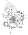
- crankshaft 6 of the engine unit is journalled between the cylinder block 7 and the bearing case 8 as shown in Figs. 5 to 7, and is connected with each piston 9 provided in the respective cylinder through the respective connecting rod 10.
- a disk 90 having projections 90a mounted on its periphery is provided on one end of the crankshaft 6 projecting out of the cylinder block 7 to detect the phase of the crankshaft rotation by sensing the passing of the projection 90a mounted on the disk 90 by a crank sensor 91 mounted on the cylinder block 7.
- a cylinder head 11 constituting the engine E On which head 11 is provided a head cover 12, and each cylinder is provided with an ignition plug 13.
- the bearing case 8 is provided with an oil pan 14 connected with an oil tank 15 which tank 15 is disposed forwardly of the vehicle from the bottom to the top of the engine through the entire height of the engine.
- the cylinder bank of the engine is inclined from the verticality backward of the vehicle.
- the power takout shaft 16 for taking out the output power of the crankshaft 6 is disposed in parallel with the crankshaft 6 and further is disposed slantly forwardly above the crankshaft 6.
- the oil tank 15 reserving engine oil is located slantly forwardly under the crankshaft 6 and the power output shaft 16 and is thus faced forwardly of the vehicle as shown by the arrow mark FWD in Figs. 3, 4 and 6.
- the power takeout shaft 16 is positioned in such a manner that the angle formed between the cylinder axis plane L1 and the plane L2 including both of the crankshaft 6 axis and the power output shaft 16 axis may be an acute angle.
- the oil pan 14 has a pair of oil passages 17 formed vertically through both sides of the guide portion 14a as shown in Fig. 6, and the engine oil collected in the oil pan 14 is sucked in through the inlet port 17a at the bottom of the oil passage 17 and is sent to the oil tank 15 by discharge pumps 18 and 19 mounted on the power takeout shaft 16.
- the oil pan 14 and the oil tank 15 is partitioned by a wall provided with oil passages 17.
- the oil which has lubricated various portions of the engine is collected at the bottom of the crank chamber A formed with the cylinder block 7, bearing case 8 and oil pan 14, and the inlet port 17a is provided with a net 20 so that dust may not be sucked in.
- Inside the oil pan 14 is mounted a plate 21 on the guide portion 14a.
- the oil reserved in the tank 15 is sucked through a strainer 25 and a pipe 26 disposed at the bottom of the tank 15 and then is fed to various lubricating points in the engine by the oil pump 24 provided on the power output shaft 16 through an oil cooler 22 and an oil filter 23, then through an oil passage 14b formed through the oil pan 14 and an oil passage 8a formed through the bearing case, and further through oil passages 7a and 11a formed through the cylinder block 7 and the cylinder head 11, respectively.
- the oil tank 15 is provided, at its top, with an oil refill mouth 15a closed by a refill cap 27, and is further provided with a breather portion 15b by forming a labyrinth with partitions (not shown) within its top portion.
- crankshaft 6 has a gear 28 formed around one of its crankarms, and this gear 28 is in engagement with the gear 29 mounted on the power takout shaft 16.
- Power transmission from the crankshaft 6 to the power takeout shaft 16 is not limited to through gears 28 and 29 as described above, but may be through a chain, and the gears or the chain may be arbitrarily positioned at one end of the crankshaft or midway of it.
- the countershaft 31 is journalled on the cylinder head 11 on one side of the cylinder block 7, and the gear 30 provided on the power takeout shaft 16 is connected to the gear 32 on the countershaft 31 through a first chain 33, with a reduction ratio of, e.g., 0.8. Further, the gear 34 mounted on this countershaft 31 is connected to the gears 38 on the camshafts 37 for the valve operating mechanism 36 through a second chain 35 with a reduction ratio of, e.g., 0.6, so that the camshafts 37 may be rotated by the rotation of the crankshaft 6.
- the cams 39 formed integrally with the camshafts 37 are rotated together with the camshafts 37 and operate the intake and exhaust valves (not shown) to open/close the intake and exhaust passages 11c and 11d formed through the cylinder head 11 with predetermined timings.
- the camshafts 37 are rotatably journalled on the cylinder head 11 through a cam cap 102.
- Each intake passage 11c is provided with a fuel injector (not shown) to supply fuel with predetermined timings.
- the countershaft 31 is jounalled on the cylinder head 11 above the power takeout shaft 16 and under the intake passage 11c and an intake pipe 41 leading from this intake passage 11c.
- the first chain 33 is extended along the cylinder axes, and further, as shown in Figs. 8 through 10, is positioned between the cylinders X1 and X2 on one side of the cylinder X1.
- the second chain 35 is positioned on the other side of the cylinder X1 on one side of the engine.
- the cylinder head 11 supporting the countershaft 31 has accommodation openings 112 and 113 formed for accommodating gears 32 and 34 both mounted on the countershaft 31, and covered by a cap 114 and a cover 116, respectively.
- the accommodation opening 112 on the side on which is connected the first chain 33 is opened slantly upward.
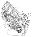
- the water pump 120 is positioned within the width of the engine proper E in the crankshaft direction.
- a water inlet fitting 123 On the suction side of this water pump 121 is provided a water inlet fitting 123, which is connected to the outlet of the radiator 5 through a piping 124.
- the water inlet fitting 123 is incorporated with a regulating valve 125 provided with a thermostat 126 for allowing the coolant water to flow into the water pump 120 when the temperature of the coolant water within the engine is over a predetermined limit.
- the delivery port 129 on the delivery side of the water pump 120 is connected to the coolant water inlet 130 provided on the front (with respect to the vehicle) side of the cylinder block 7, and the coolant water is supplied to the coolant water passage 132 formed within the cylinder head 11 from this coolant water inlet 130 through a coolant water passage 131 formed within the cylinder block 7 around the drive shaft 121.
- This coolant water inlet 131 is required only to be positioned on the side faces forwardly of the vehicle, and it may be directed either laterally of the vehicle as in this embodiment or forwardly of the vehicle.
- the water pump 120 is mounted on the cylinder block 7 in such a manner that the coolant water inlet 130 of the cylinder block 7 is covered by the delivery port 129 of the water pump 120, no piping is required to connect the coolant water inlet 130 to the delivery port 129. Further, since the coolant water passage 131 and the coolant water inlet 130 formed through the cylinder block 7 are formed through one side face of the bearing portion 133 swelling forwardly of the cylinder block 7, they require no particular swelling to be formed on the cylinder block 7, which will prevent the engine proper E from becoming bulky.
- the coolant water passage 131 formed through the cylinder block 7 is opened on the top end face of the cylinder block 7, and the coolant water passage 132 of the cylinder head 11 is opened on the bottom face of the cylinder head 11.
- the opening 131a of the coolant water passage 131 on the cylinder block side is opened opposite to the opening 132a of the coolant water passage 132 on the cylinder head side. Therefore, the coolant water passages 131 and 132 can be communicated with each other only by mounting the cylinder head 11 on the cylinder block 7.
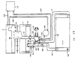
- the coolant water passage 131 does not join the water jacket 134 for the cylinder block 7 but is communicated with the coolant water passage 132 formed within the cylinder head 11, and through this coolant water passage 132 is led the coolant water to a main passage 135a of the water jacket 135 formed within the cylinder head 11. This flow of the coolant water is shown by arrow marks in Fig. 15.
- the coolant water inlet 132a of the head water jacket 135 for the cylinder head 11 is opened at a height lower than the intake passage 11c and the intake pipe 41, and further since the coolant water passage 132 is formed integrally with the cylinder head 11, the coolant water passage 132 will not interfere with the intake passage 11c and the intake pipe 41, which facilitates arrangement of the coolant water passage.
- the water pump 120 is mounted on the cylinder block 7 and the coolant water is supplied to the head water jacket 135 for the calinder head 11 through coolant water passages 131 and 132 provided independently of the block water jacket 134 as described above, although the cylinder head 11 is cooled prior to the cylinder block 7, the water pump 120 can be disposed without interfering with the intake pipe 41, exhaust pipe 40, etc., which makes it possible to obtain a compact engine unit.
- the water pump 120 and the coolant water inlet 132a of the head water jacket 135 are positioned on the side faces, on the same side parallel to the crankshaft 6, of the cylinder block 7 and the cylinder head 11 respectively, the water pump 120 and the coolant water passage 131 will not overlap with each other longitudinally of the crankshaft 6, which makes it possible to shorten the engine unit longitudinally of the crankshaft 6.
- the mounting seats 120a for the water pump 120, the coolant water inlet 132a of the head water jacket 135 and the coolant water inlet 130a of the coolant water passage 131 are required only to be positioned on the side faces, parallel to the crankshaft 6, of the cylinder head 11 or the cylinder block 7, and they are not necessarily to be opened perpendicularly to the crankshaft 6. In this embodiment, they are opened longitudinally of the crankshaft 6 or of the cylinder axis.
- the coolant water passage 131 may be formed with a hose or the like separate from the cylinder block 7. Further, the water pump 120 and the coolant water passage 131 may be provided on the exhaust side.
- the cylinder head 11 is fastened on the cylinder block 7 through bolts 137 inserted through boss portion 136 between cylinders, is provided with intake passages 11c and exhaust passages 11d formed on one and the other side of and above each combustion chamber, and is further provided with an ignition plug 13 fastened at the center of each combustion chamber.
- the water jacket 135 for the cylinder head 11 is formed around the boss portions 136, intake passages 11c and exhaust passages 11d. Between these cylinders are provided flow regulating portions 138 in which are formed guide portions 138a to guide the coolant water so that the coolant water may flow with a prescribed speed to cool the cylinder head 11. These flow regulating portions 138 are positioned on the exhaust side effectively to cool the exhaust side whose temperature is apt to be higher than the intake side. Further, the guide portion 138a of the flow regulating portion 138 is positioned in such a manner that their tips are offset by a distance Z from ignition plugs 13 to the exhaust side to elevate the cooling effect by leading the coolant water toward the exhaust side of the ignition plugs 13. This flow of the coolant water within the cylinder head 11 is shown by arrow marks in Figs. 12 and 13.
- the coolant water in the head water jacket 135 for the cylinder head 11 is supplied from the communicating passages 139 through the lower portion of the cylinder head 11 to the block water jacket 134 through communicating passages 139 formed through the cylinder block 7 to cool the cylinder block 7. Accordingly, the coolant water is first led to the cylinder head 11 to cool it whose temperature is apt to become higher due to engine operation, and then cools the cylinder block 7, so that the engine can be cooled effectively.
- the coolant water outlet 140 communicated with the water jacket 134 formed within the cylinder block 7 is formed on the front side of the cylinder block 7 in the vicinity of the water pump 120. On this coolant water outlet 140 is fastened a water outlet fitting 127 which is communicated with the inlet side of the radiator 5 through a piping 141.
- the radiator 5 is provided with a fan switch 142. The inlet and the outlet of the radiator 5 are positioned symmetrically to each other to make the coolant flow across the radiator 5.
- the coolant water flows as shown by arrow marks in Fig. 13. That is, while the engine is running and the coolant water temperature has reached a prescribed limit, the thermostat 126 in the regulating valve 125 works to intercept the bypass passage 128 while communicating the water inlet fitting 123 with the water pump 120 to send the coolant water from the radiator 5 to the cylinder head 11 and the cylinder block 7 by the water pump 120 through the water inlet fitting 123 to cool them. The coolant water after cooling the cylinder block 7 is returned to the radiator 5 through the water outlet fitting 127.
- this water outlet fitting 127 is provided with a water temperature sender 143 and a water temperature sensor 144.
- This water outlet fitting 127 provided on the water outlet 140 is communicated with the water inlet fitting 123 through a bypass passage 128 on the front side of the cylinder block 7, and, by mounting this water outlet fitting 127, water inlet fitting 123 and water pump 120 in parallel and close to one another, the bypass passage 128 and water pump 120 in parallel and close to one another, the bypass passage 128 can be shortened and piping can be facilitated while heat loss can be reduced.
- the water outlet fitting 127 and the water pump 120 may be mounted on the contrary positions so that the coolant water may be supplied to the cylinder block prior to the cylinder head.
- two coolant water pipings 145 and 146 are connected to the upper portion of the cylinder head 11, the formeer 145 being connected to the water pump 120 through a heater 147 and the latter 146 being joined to the piping 145 through an oil cooler 148 to he connected to the water pump 120.
- the oil cooler 148 is cooled by this coolant water while engine operation, and the heater 147 supplies warm air into the passenger compartment when necessary while engine operation. Since the coolant water temperature is low just after engine start, the regulating valve 125 in the water inlet fitting 123 intercepts the cooling water supply from the radiator 5 making the bypass passage 128 communicative through the action of the thermostat 126, and the coolant water from the cylinder head 11 is circulated by the water pump 120 from the water outlet fitting 127 and the bypass passage 128 through the water pump 120 to the cylinder head 811 and the cylinder block 7.
- the thermostat 126 of the regulating valve 125 works to communicate the water inlet fitting 123 with the water pump while intercepting the bypass passage 128, and the coolant water is sent to the radiator 5 through the water outlet fitting 127 to be cooled through heat-exchange there, then cools the cylinder head 11 and the cylinder block 7 through circulation by the water pump 120.
- the position of the coolant water piping 146 is not limited to one shown in Fig. 5, but may be on th end face of the cylinder head 11 opposite to that on which the second chain 35 is provided as shown in Fig. 14. In this case shown in Fig. 14, since the coolant water piping 146 is connected to the highest position of the water jacket 135, the water jacket 135 can be securely bleeded of air.
- the cylinder head 11 has exhaust pipes 40 and intake pipes 41 connected to each cylinder.
- Each intake pipe 41 is connected to a surge tank 42 which is extended laterally of the vehicle and supported on the cylinder block 7 through stays 43.
- This surge tank 42 is provided with a throttle valve 44 at its air inlet end.
- a flywheel 45 on one end of the power takeout shaft 16 is provided a flywheel 45 and a clutch mechanism (not shown), so that the power may be transmitted to the front wheel shafts 2 for front wheels 3 through a transmission 47.
- the primary side of the transmission 47 is disposed on the power takeout shaft 16, and the secondary side is disposed on a countershaft 48 to rotate the front wheel shaft 2 through a gear 49 provided on the wheel shaft 2.
- auxiliary drive pulley 50 On the other end of the power takeout shaft 16 is provided an auxiliary drive pulley 50 with its periphery accommodated within a concave 51 provided at an end of the cylinder block 7 laterally opposite to a bearing 60 for the crankshaft 6 as shown in Fig. 7, and a belt 55 is wrapped around this auxiliary drive pulley 50 and the auxiliary pulleys for auxiliaries such as alternator 52, power steering pump 53, air compressor 54, etc., so that these auxiliaries are simultaneously driven by the power takeout shaft 16.
- the tension of this belt 55 can be adjusted through an idler pulley 92.
- a drive shaft 121 which is rotated through the first chain 33 originally for transmitting the rotation of the powere takeout shaft 16 to the countershaft 31, is employed in this embodiment as the drive shaft to which is to be transmitted the rotation of the crankshaft 6, the water pump 120 may be provided instead on the power takeout shaft 16 or on the countershaft 31.
Abstract
Description
- The present invention relates to a cooling system for an internal combustion engine comprising a cylinder head affixed to a cylinder block and a cylinder head coolant jacket for circulating coolant through said cylinder head.
- As it is well known, it is desirable to take care to lower preferably the temperature of the cylinder head enabling to increase the engine output by increasing the permissible combustion temperature. Of course, such a strategy requires improved and forced cooling of the cylinder head. Therefore, it has been deliberated to mount the water pump directly on the cylinder head, in particular to install it at one side of the engine, intending to supply cooling water to the cylinder head prior to supplying cooling water to the cylinder block cooling structure. However, under said design aspects, the internal combustion engine tends to become bulky because the side face of the cylinder head in a crankshaft direction is provided with intake and exhaust pipes and any location of the water pump at the cylinder head requires to avoid interference with these pipes.
- In order to provide a compact cooling structure, it has already been proposed, to connect the delivery port of a coolant pump with a coolant jacket for the cylinder block. The cylinder block coolant jacket is communicated with the cylinder head coolant jacket via passages integrally formed in the cylinder block and the cylinder head, respectively, so that the coolant which is introduced into the cylinder block coolant jacket from the discharge side of the pump and circulated through said cylinder block coolant jacket, flows into the cylinder head coolant jacket after cooling the cylinder block and is then circulated in said cylinder head coolant jacket.
- US-4 699 092 shows a coolant jacket arrangement of a cylinder head, wherein an annular coolant chamber is associated with each cylinder formed in the cylinder block and the cylinder head. The coolant is introduced into the cylinder head coolant jacket through inlet orifices formed in the bottom portion of the cylinder head and connected to the cylinder block coolant jacket, and flows through said coolant chamber towards the uppermost portion thereof, where a discharge passage emanates from.
- Aside from the fact that this known cooling arrangement cannot provide forced cooling of the cylinder head, as it cools first the cylinder block, it is not satisfactory regarding the flowing direction and regulation of the flowing speed of the coolant circulating through the cylinder head coolant jacket.
- It is therefore an objective of the present invention to provide an improved cooling system for an internal combustion engine, which system enables an improved cooling of the cylinder head structure and compensates the increased temperature load caused by the combustion process occurring in the combustion chamber defined by the cylinder head structure.
- According to the present invention, this objective is performed in that a flow regulating member is provided in the cylinder head coolant jacket between adjacent cylinders for regulating a transverse flow of coolant through the cylinder head jacket between the intake and exhaust sides thereof.
- Since the temperature load on the cylinder head structure usually differs between the intake side and the exhaust side thereof, the coolant flows transversely through the coolant jacket between the intake and exhaust side and the regulating member is arranged in said transverse flow so that the coolant may flow with a prescribed speed, enabling a very efficient and high precision cooling of the cylinder head structure.
- According to another aspect of the invention, said objective is performed in that the cylinder head coolant jacket is communicated with a cylinder block coolant jacket for circulating the coolant therethrough after cooling the cylinder head and a coolant main passage is formed along one side of the cylinder head for circulating the coolant through the cylinder head coolant jacket transversely from said one side to the opposite side of the cylinder head.
- Accordingly, the coolant flows transversely through the coolant jacket of the cylinder head so as to provide an increased cooling of the cylinder head and flows then into the cylinder block coolant jacket and is circulated therethrough so as to cool the cylinder block after cooling the cylinder head.
- According to a preferred embodiment of the present invention, the cylinder head coolant jacket forms a first passage between adjacent cylinders on the intake side of the cylinder head and a second passage on the exhaust side of the cylinder head between said adjacent cylinders, the width of said first passage being smaller than the width of said second passage.
- Thus, the volume of the coolant surrounding the hot exhaust passages is larger than on the intake side and the speed of the coolant flowing on the exhaust side is decreased in comparison with the intake side, so that effective cooling of the exhaust side, whose temperature is apt to be higher, is achieved.
- Further preferred embodiments of the invention are laid down in the further subclaims.
- Hereinafter the present invention is illustrated and explained in greater detail by means of a preferred embodiment and accompanying drawings, wherein:
- Figure 1 is a side view showing the assembled state of an automotive internal combustion engine according to the present invention,
- Figure 2 is a plan view for Figure 1,
- Figure 3 is a side view of the internal combustion engine shown in Figure 1,
- Figure 4 is a front view of the internal combustion engine of Figure 3,
- Figures 5 and 6 are partially broken-away side views of the internal combustion engine of Figure 1,
- Figure 7 is a sectional view along the line VII-VII in Figure 6,
- Figure 8 is a sectional view along the line VII-VII in Figure 5,
- Figure 9 is a plan view of the cylinder block of the internal combustion engine according to Figure 1,
- Figure 10 is an arrow view along the
arrow mark 1 in Figure 9, - Figure 11 is a sectional view along the line XI-XI in Figure 10,
- Figure 12 is a vertical sectional view of the cylinder head of the internal combustion engine of Figure 1,
- Figure 13 is a sectional view along the line XIII-XIII in Figure 12,
- Figure 14 is a side view of the cylinder head of the internal combustion engine according to the present invention on the side opposite to that on which a second drive chain is provided, and
- Figure 15 is a system diagram of the cooling system of the internal combustion engine according to the present invention.
- In Figures 1 and 2, the
reference number 1 denotes the engine compartment of an automobile formed above and between the right and leftfront wheels 3 connected throughfront wheel shafts 2. Within thisengine compartment 1 is mounted anengine unit 4 having a 4-stroke 6-cylinder internal combustion engine with itsradiator 5 arranged in front of thisengine unit 4. Theengine unit 4 is disposed with itscrankshaft 6 extending laterally of the vehicle so that the passenger compartment may be spacious. - The
crankshaft 6 of the engine unit is journalled between thecylinder block 7 and thebearing case 8 as shown in Figs. 5 to 7, and is connected with eachpiston 9 provided in the respective cylinder through the respective connecting rod 10. As shown in Figs. 3 and 7 in double-dotted chain lines, adisk 90 havingprojections 90a mounted on its periphery is provided on one end of thecrankshaft 6 projecting out of thecylinder block 7 to detect the phase of the crankshaft rotation by sensing the passing of theprojection 90a mounted on thedisk 90 by acrank sensor 91 mounted on thecylinder block 7. - On the
cylinder block 7 is mounted acylinder head 11 constituting the engine E, on whichhead 11 is provided ahead cover 12, and each cylinder is provided with anignition plug 13. - The
bearing case 8 is provided with anoil pan 14 connected with anoil tank 15 whichtank 15 is disposed forwardly of the vehicle from the bottom to the top of the engine through the entire height of the engine. - As shown in Figs. 5 and 6, the cylinder bank of the engine is inclined from the verticality backward of the vehicle. The power takout
shaft 16 for taking out the output power of thecrankshaft 6 is disposed in parallel with thecrankshaft 6 and further is disposed slantly forwardly above thecrankshaft 6. Theoil tank 15 reserving engine oil is located slantly forwardly under thecrankshaft 6 and thepower output shaft 16 and is thus faced forwardly of the vehicle as shown by the arrow mark FWD in Figs. 3, 4 and 6. Thepower takeout shaft 16 is positioned in such a manner that the angle formed between the cylinder axis plane L1 and the plane L2 including both of thecrankshaft 6 axis and thepower output shaft 16 axis may be an acute angle. - The
oil pan 14 has a pair ofoil passages 17 formed vertically through both sides of theguide portion 14a as shown in Fig. 6, and the engine oil collected in theoil pan 14 is sucked in through theinlet port 17a at the bottom of theoil passage 17 and is sent to theoil tank 15 bydischarge pumps power takeout shaft 16. Theoil pan 14 and theoil tank 15 is partitioned by a wall provided withoil passages 17. The oil which has lubricated various portions of the engine is collected at the bottom of the crank chamber A formed with thecylinder block 7,bearing case 8 andoil pan 14, and theinlet port 17a is provided with anet 20 so that dust may not be sucked in. Inside theoil pan 14 is mounted aplate 21 on theguide portion 14a. - The oil reserved in the
tank 15 is sucked through astrainer 25 and apipe 26 disposed at the bottom of thetank 15 and then is fed to various lubricating points in the engine by theoil pump 24 provided on thepower output shaft 16 through anoil cooler 22 and anoil filter 23, then through anoil passage 14b formed through theoil pan 14 and an oil passage 8a formed through the bearing case, and further through oil passages 7a and 11a formed through thecylinder block 7 and thecylinder head 11, respectively. - This circulation of oil is shown by arrow marks in Fig. 6.
- The
oil tank 15 is provided, at its top, with anoil refill mouth 15a closed by arefill cap 27, and is further provided with abreather portion 15b by forming a labyrinth with partitions (not shown) within its top portion. - As shown in Figs. 7 and 8, the
crankshaft 6 has agear 28 formed around one of its crankarms, and thisgear 28 is in engagement with thegear 29 mounted on the power takoutshaft 16. - Power transmission from the
crankshaft 6 to thepower takeout shaft 16 is not limited to throughgears - The
countershaft 31 is journalled on thecylinder head 11 on one side of thecylinder block 7, and thegear 30 provided on thepower takeout shaft 16 is connected to thegear 32 on thecountershaft 31 through afirst chain 33, with a reduction ratio of, e.g., 0.8. Further, thegear 34 mounted on thiscountershaft 31 is connected to thegears 38 on thecamshafts 37 for thevalve operating mechanism 36 through asecond chain 35 with a reduction ratio of, e.g., 0.6, so that thecamshafts 37 may be rotated by the rotation of thecrankshaft 6. Thecams 39 formed integrally with thecamshafts 37 are rotated together with thecamshafts 37 and operate the intake and exhaust valves (not shown) to open/close the intake andexhaust passages 11c and 11d formed through thecylinder head 11 with predetermined timings. Thecamshafts 37 are rotatably journalled on thecylinder head 11 through acam cap 102. Eachintake passage 11c is provided with a fuel injector (not shown) to supply fuel with predetermined timings. - The
countershaft 31 is jounalled on thecylinder head 11 above thepower takeout shaft 16 and under theintake passage 11c and anintake pipe 41 leading from thisintake passage 11c. Thefirst chain 33 is extended along the cylinder axes, and further, as shown in Figs. 8 through 10, is positioned between the cylinders X1 and X2 on one side of the cylinder X1. Thesecond chain 35 is positioned on the other side of the cylinder X1 on one side of the engine. - The
cylinder head 11 supporting thecountershaft 31 hasaccommodation openings gears countershaft 31, and covered by acap 114 and acover 116, respectively. The accommodation opening 112 on the side on which is connected thefirst chain 33 is opened slantly upward. - A
drive shaft 121 for driving thewater pump 120, positioned on the front side of the engine proper E, is journalled on the front side of thecylinder block 7 in parallel to thecrankshaft 6 and thepower output shaft 16, and thegear 122 provided on thisdrive shaft 121 is in engagement with thefirst chain 33 so that thedrive shaft 122 may be rotated by and in connection with thecrankshaft 6. Since thedrive shaft 121 is on the same side of the cylinder axis plane L1 with respect to thepower takeout shaft 16 which is an indispensable component for taking out the output power of thecrankshaft 6, the engine width laterally of the crankshaft will not be particularly increased by providing thisdrive shaft 121. - As shown in Figs. 8 and 11, the
water pump 120 is positioned within the width of the engine proper E in the crankshaft direction. On the suction side of thiswater pump 121 is provided a water inlet fitting 123, which is connected to the outlet of theradiator 5 through apiping 124. As shown in Figs. 6 and 15, the water inlet fitting 123 is incorporated with a regulatingvalve 125 provided with athermostat 126 for allowing the coolant water to flow into thewater pump 120 when the temperature of the coolant water within the engine is over a predetermined limit. - The
delivery port 129 on the delivery side of thewater pump 120 is connected to thecoolant water inlet 130 provided on the front (with respect to the vehicle) side of thecylinder block 7, and the coolant water is supplied to thecoolant water passage 132 formed within thecylinder head 11 from thiscoolant water inlet 130 through acoolant water passage 131 formed within thecylinder block 7 around thedrive shaft 121. Thiscoolant water inlet 131 is required only to be positioned on the side faces forwardly of the vehicle, and it may be directed either laterally of the vehicle as in this embodiment or forwardly of the vehicle. - Since the
water pump 120 is mounted on thecylinder block 7 in such a manner that thecoolant water inlet 130 of thecylinder block 7 is covered by thedelivery port 129 of thewater pump 120, no piping is required to connect thecoolant water inlet 130 to thedelivery port 129. Further, since thecoolant water passage 131 and thecoolant water inlet 130 formed through thecylinder block 7 are formed through one side face of the bearingportion 133 swelling forwardly of thecylinder block 7, they require no particular swelling to be formed on thecylinder block 7, which will prevent the engine proper E from becoming bulky. - As shown in Figs. 9 and 11, the
coolant water passage 131 formed through thecylinder block 7 is opened on the top end face of thecylinder block 7, and thecoolant water passage 132 of thecylinder head 11 is opened on the bottom face of thecylinder head 11. Theopening 131a of thecoolant water passage 131 on the cylinder block side is opened opposite to theopening 132a of thecoolant water passage 132 on the cylinder head side. Therefore, thecoolant water passages cylinder head 11 on thecylinder block 7. - The
coolant water passage 131 does not join thewater jacket 134 for thecylinder block 7 but is communicated with thecoolant water passage 132 formed within thecylinder head 11, and through thiscoolant water passage 132 is led the coolant water to a main passage 135a of thewater jacket 135 formed within thecylinder head 11. This flow of the coolant water is shown by arrow marks in Fig. 15. - Since the
coolant water inlet 132a of thehead water jacket 135 for thecylinder head 11 is opened at a height lower than theintake passage 11c and theintake pipe 41, and further since thecoolant water passage 132 is formed integrally with thecylinder head 11, thecoolant water passage 132 will not interfere with theintake passage 11c and theintake pipe 41, which facilitates arrangement of the coolant water passage. - Thus, since the
water pump 120 is mounted on thecylinder block 7 and the coolant water is supplied to thehead water jacket 135 for the calinderhead 11 throughcoolant water passages block water jacket 134 as described above, although thecylinder head 11 is cooled prior to thecylinder block 7, thewater pump 120 can be disposed without interfering with theintake pipe 41,exhaust pipe 40, etc., which makes it possible to obtain a compact engine unit. - Further, since the
water pump 120 and thecoolant water inlet 132a of thehead water jacket 135 are positioned on the side faces, on the same side parallel to thecrankshaft 6, of thecylinder block 7 and thecylinder head 11 respectively, thewater pump 120 and thecoolant water passage 131 will not overlap with each other longitudinally of thecrankshaft 6, which makes it possible to shorten the engine unit longitudinally of thecrankshaft 6. - The mounting seats 120a for the
water pump 120, thecoolant water inlet 132a of thehead water jacket 135 and the coolant water inlet 130a of thecoolant water passage 131 are required only to be positioned on the side faces, parallel to thecrankshaft 6, of thecylinder head 11 or thecylinder block 7, and they are not necessarily to be opened perpendicularly to thecrankshaft 6. In this embodiment, they are opened longitudinally of thecrankshaft 6 or of the cylinder axis. - The
coolant water passage 131 may be formed with a hose or the like separate from thecylinder block 7. Further, thewater pump 120 and thecoolant water passage 131 may be provided on the exhaust side. - As shown in Figs. 12 and 13, the
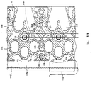
cylinder head 11 is fastened on thecylinder block 7 throughbolts 137 inserted throughboss portion 136 between cylinders, is provided withintake passages 11c and exhaust passages 11d formed on one and the other side of and above each combustion chamber, and is further provided with anignition plug 13 fastened at the center of each combustion chamber. - The
water jacket 135 for thecylinder head 11 is formed around theboss portions 136,intake passages 11c and exhaust passages 11d. Between these cylinders are providedflow regulating portions 138 in which are formedguide portions 138a to guide the coolant water so that the coolant water may flow with a prescribed speed to cool thecylinder head 11. theseflow regulating portions 138 are positioned on the exhaust side effectively to cool the exhaust side whose temperature is apt to be higher than the intake side. Further, theguide portion 138a of theflow regulating portion 138 is positioned in such a manner that their tips are offset by a distance Z from ignition plugs 13 to the exhaust side to elevate the cooling effect by leading the coolant water toward the exhaust side of the ignition plugs 13. This flow of the coolant water within thecylinder head 11 is shown by arrow marks in Figs. 12 and 13. - Further, as shown in Fig. 6, the coolant water in the
head water jacket 135 for thecylinder head 11 is supplied from the communicatingpassages 139 through the lower portion of thecylinder head 11 to theblock water jacket 134 through communicatingpassages 139 formed through thecylinder block 7 to cool thecylinder block 7. Accordingly, the coolant water is first led to thecylinder head 11 to cool it whose temperature is apt to become higher due to engine operation, and then cools thecylinder block 7, so that the engine can be cooled effectively. - The
coolant water outlet 140 communicated with thewater jacket 134 formed within thecylinder block 7 is formed on the front side of thecylinder block 7 in the vicinity of thewater pump 120. On thiscoolant water outlet 140 is fastened a water outlet fitting 127 which is communicated with the inlet side of theradiator 5 through apiping 141. Theradiator 5 is provided with afan switch 142. The inlet and the outlet of theradiator 5 are positioned symmetrically to each other to make the coolant flow across theradiator 5. - Accordingly, the coolant water flows as shown by arrow marks in Fig. 13. That is, while the engine is running and the coolant water temperature has reached a prescribed limit, the
thermostat 126 in the regulatingvalve 125 works to intercept thebypass passage 128 while communicating the water inlet fitting 123 with thewater pump 120 to send the coolant water from theradiator 5 to thecylinder head 11 and thecylinder block 7 by thewater pump 120 through the water inlet fitting 123 to cool them. The coolant water after cooling thecylinder block 7 is returned to theradiator 5 through the water outlet fitting 127. - As shown in Fig. 15, this water outlet fitting 127 is provided with a
water temperature sender 143 and awater temperature sensor 144. This water outlet fitting 127 provided on thewater outlet 140 is communicated with the water inlet fitting 123 through abypass passage 128 on the front side of thecylinder block 7, and, by mounting this water outlet fitting 127, water inlet fitting 123 andwater pump 120 in parallel and close to one another, thebypass passage 128 andwater pump 120 in parallel and close to one another, thebypass passage 128 can be shortened and piping can be facilitated while heat loss can be reduced. - Hereupon, the water outlet fitting 127 and the
water pump 120 may be mounted on the contrary positions so that the coolant water may be supplied to the cylinder block prior to the cylinder head. - As shown in Fig. 15, two
coolant water pipings cylinder head 11, theformeer 145 being connected to thewater pump 120 through aheater 147 and the latter 146 being joined to the piping 145 through an oil cooler 148 to he connected to thewater pump 120. - The
oil cooler 148 is cooled by this coolant water while engine operation, and theheater 147 supplies warm air into the passenger compartment when necessary while engine operation. Since the coolant water temperature is low just after engine start, the regulatingvalve 125 in the water inlet fitting 123 intercepts the cooling water supply from theradiator 5 making thebypass passage 128 communicative through the action of thethermostat 126, and the coolant water from thecylinder head 11 is circulated by thewater pump 120 from the water outlet fitting 127 and thebypass passage 128 through thewater pump 120 to the cylinder head 811 and thecylinder block 7. - After the engine is started and the coolant water temperature has reached a prescribed limit, the
thermostat 126 of the regulatingvalve 125 works to communicate the water inlet fitting 123 with the water pump while intercepting thebypass passage 128, and the coolant water is sent to theradiator 5 through the water outlet fitting 127 to be cooled through heat-exchange there, then cools thecylinder head 11 and thecylinder block 7 through circulation by thewater pump 120. - Since the coolant water is continually circulated from the coolant water piping 146 connected to the
cylinder head 11 through theoil cooler 148 while the engine is running, air is prevented from being collected within thewater jacket 135 for thecylinder head 11 even when the coolant water is circulated for cooling from thecylinder head 11 to thecylinder block 7. - The position of the coolant water piping 146 is not limited to one shown in Fig. 5, but may be on th end face of the
cylinder head 11 opposite to that on which thesecond chain 35 is provided as shown in Fig. 14. In this case shown in Fig. 14, since the coolant water piping 146 is connected to the highest position of thewater jacket 135, thewater jacket 135 can be securely bleeded of air. - The
cylinder head 11 hasexhaust pipes 40 andintake pipes 41 connected to each cylinder. Eachintake pipe 41 is connected to asurge tank 42 which is extended laterally of the vehicle and supported on thecylinder block 7 through stays 43. Thissurge tank 42 is provided with athrottle valve 44 at its air inlet end. - As shown in Fig. 1, on one end of the
power takeout shaft 16 is provided aflywheel 45 and a clutch mechanism (not shown), so that the power may be transmitted to thefront wheel shafts 2 forfront wheels 3 through atransmission 47. The primary side of thetransmission 47 is disposed on thepower takeout shaft 16, and the secondary side is disposed on acountershaft 48 to rotate thefront wheel shaft 2 through a gear 49 provided on thewheel shaft 2. - On the other end of the
power takeout shaft 16 is provided anauxiliary drive pulley 50 with its periphery accommodated within a concave 51 provided at an end of thecylinder block 7 laterally opposite to abearing 60 for thecrankshaft 6 as shown in Fig. 7, and abelt 55 is wrapped around thisauxiliary drive pulley 50 and the auxiliary pulleys for auxiliaries such asalternator 52,power steering pump 53,air compressor 54, etc., so that these auxiliaries are simultaneously driven by thepower takeout shaft 16. The tension of thisbelt 55 can be adjusted through anidler pulley 92. - Although a
drive shaft 121, which is rotated through thefirst chain 33 originally for transmitting the rotation of thepowere takeout shaft 16 to thecountershaft 31, is employed in this embodiment as the drive shaft to which is to be transmitted the rotation of thecrankshaft 6, thewater pump 120 may be provided instead on thepower takeout shaft 16 or on thecountershaft 31.
Claims (11)
- Cooling system for a multiple cylinder internal combustion engine comprising a cylinder head (11) affixed to a cylinder block (7) defining a plurality of cylinders and a cylinder head coolant jacket (135) for circulating coolant between an intake and exhaust side of the cylinder head (11), said cylinder head (11) having at least one intake passage (11c) extending through one side of said cylinder head (11) and at least one exhaust passage (11d) extending through another side of said cylinder head (11), characterised in that a flow regulating member (138) is provided in the cylinder head coolant jacket (135) between adjacent cylinders (x1, x2) for regulating a transverse flow of coolant through the cylinder head jacket (135) between the intake and exhaust sides thereof.
- Cooling system for an internal combustion engine comprising a cylinder head (11) affixed to a cylinder block (7), a cylinder head coolant jacket (135) and a cylinder block coolant jacket (134) for circulating coolant through the cylinder head (11) and the cylinder block (7), respectively, particularly as claimed in claim 1, characterised in that the cylinder head coolant jacket (135) is communicated with the cylinder block coolant jacket (134) for circulating the coolant therethrough after cooling the cylinder head (11), and a coolant main passage (135a) is formed along one side of the cylinder head (11) for circulating the coolant through the cylinder head coolant jacket transversely from said one side to the opposite side of the cylinder head (11).
- Cooling system as claimed in claim 1 or 2, characterised in that a plurality of flow regulating members (138) are provided between adjacent cylinders (x1, x2...x6) arranged in line.
- Cooling system as claimed in at least one of claims 1 to 3, characterised in that the flow regulating members (138) are substantially cross-shaped and provided with guide portions (138a) for directing the coolant flowing from the intake to the exhaust side of the cylinder head (11) towards center portions of the cylinder head (11) provided with a spark plug (13) associated with each of said cylinders (x1, x2).
- Cooling system as claimed in at least one of claims 1 to 4, characterised in that the flow regulating members (138) are offset from a plane (L1) connecting the center axis of the cylinders (x1, x2) arranged in line towards the exhaust side of the cylinder head (11).
- Cooling system as claimed in at least one of claims 1 to 5, characterised in that the cylinder head coolant jacket (135) forms a first passage between adjacent cylinders (x1, x2) on the intake side of the cylinder head (11) and a second passage on the exhaust side of the cylinder head (11) between said adjacent cylinders (x1, x2), the width (A) of said first passage being smaller than the width (B) of said second passage.
- Cooling system as claimed in at least one of claims 4 to 6, characterised in that the guide portions (138a) are integrally formed with the regulating member (138) on opposite sides thereof.
- Cooling system as claimed in at least one of claims 1 to 7, characterised in that the regulating members (138) are integrally formed with the cylinder head (11).
- Cooling system as claimed in at least one of claims 1 to 8, characterised in that the cylinder head coolant jacket (135) is formed around three intake passages (11c) associated with three intake valves and two exhaust passages (11d) associated with two exhaust valves for each cylinder (x1, x2) and around a boss portion (136) disposed in front of a coolant jacket passage defined between two intake passages (11c) for directing the coolant towards the regulating member (138).
- Cooling system as claimed in claim 9, characterised in that the boss portion (136) is provided with guide tip portions for directing the flow of coolant towards the coolant jacket passage defined between the intake passages (11c).
- Cooling system as claimed in at least one of claims 1 to 10, characterised in that the cylinder head coolant jacket (135) is communicated with the cylinder block coolant jacket (134) via communicating passages (139) disposed at the intake and exhaust side of the regulating member (138), respectively.
Applications Claiming Priority (9)
| Application Number | Priority Date | Filing Date | Title |
|---|---|---|---|
| JP17467589 | 1989-07-06 | ||
| JP174676/89 | 1989-07-06 | ||
| JP174675/89 | 1989-07-06 | ||
| JP1174676A JP2802440B2 (en) | 1989-07-06 | 1989-07-06 | Engine unit for vehicle |
| JP186614/89 | 1989-07-19 | ||
| JP186616/89 | 1989-07-19 | ||
| JP1186616A JP2704659B2 (en) | 1989-07-19 | 1989-07-19 | Engine unit for vehicle |
| JP1186614A JP3008199B2 (en) | 1989-07-19 | 1989-07-19 | Engine unit for vehicle |
| EP93105961A EP0560402B1 (en) | 1989-07-06 | 1990-06-27 | Automotive internal combustion engine |
Related Parent Applications (2)
| Application Number | Title | Priority Date | Filing Date |
|---|---|---|---|
| EP93105961.2 Division | 1990-06-27 | ||
| EP93105961A Division EP0560402B1 (en) | 1989-07-06 | 1990-06-27 | Automotive internal combustion engine |
Publications (3)
| Publication Number | Publication Date |
|---|---|
| EP0653553A2 true EP0653553A2 (en) | 1995-05-17 |
| EP0653553A3 EP0653553A3 (en) | 1995-06-28 |
| EP0653553B1 EP0653553B1 (en) | 1998-09-02 |
Family
ID=27474586
Family Applications (3)
| Application Number | Title | Priority Date | Filing Date |
|---|---|---|---|
| EP95101307A Expired - Lifetime EP0653553B1 (en) | 1989-07-06 | 1990-06-27 | Cooling system for an internal combustion engine |
| EP93105961A Expired - Lifetime EP0560402B1 (en) | 1989-07-06 | 1990-06-27 | Automotive internal combustion engine |
| EP90112308A Expired - Lifetime EP0415022B1 (en) | 1989-07-06 | 1990-06-27 | Automotive internal combustion engine with a liquid cooling system |
Family Applications After (2)
| Application Number | Title | Priority Date | Filing Date |
|---|---|---|---|
| EP93105961A Expired - Lifetime EP0560402B1 (en) | 1989-07-06 | 1990-06-27 | Automotive internal combustion engine |
| EP90112308A Expired - Lifetime EP0415022B1 (en) | 1989-07-06 | 1990-06-27 | Automotive internal combustion engine with a liquid cooling system |
Country Status (3)
| Country | Link |
|---|---|
| EP (3) | EP0653553B1 (en) |
| DE (3) | DE69030111T2 (en) |
| ES (1) | ES2054159T3 (en) |
Cited By (3)
| Publication number | Priority date | Publication date | Assignee | Title |
|---|---|---|---|---|
| EP1039098A1 (en) * | 1999-03-19 | 2000-09-27 | Tecumseh Products Company | External drive double shaft overhead cam engine (dschc) |
| FR2812030A1 (en) * | 2000-07-20 | 2002-01-25 | Daimler Chrysler Ag | "INTERNAL COMBUSTION ENGINE" |
| EP4328426A1 (en) * | 2022-08-25 | 2024-02-28 | FERRARI S.p.A. | Car provided with an internal combustion engine in which the pumps are operated by the camshafts |
Families Citing this family (5)
| Publication number | Priority date | Publication date | Assignee | Title |
|---|---|---|---|---|
| DE4402233B4 (en) * | 1994-01-26 | 2007-02-01 | Bayerische Motoren Werke Ag | Internal combustion engine with an electric starting device |
| SE505200C2 (en) * | 1996-08-30 | 1997-07-14 | Scania Cv Ab | Bus with air conditioning |
| EP0907007B1 (en) | 1997-10-02 | 2003-01-15 | Yamaha Hatsudoki Kabushiki Kaisha | Camshaft drive assembly |
| CN107676166B (en) * | 2017-11-01 | 2023-12-15 | 潍柴动力股份有限公司 | Water outlet pipe structure and engine |
| CN113236434A (en) * | 2021-04-27 | 2021-08-10 | 重庆隆鑫机车有限公司 | Cooling water jacket and engine |
Citations (6)
| Publication number | Priority date | Publication date | Assignee | Title |
|---|---|---|---|---|
| DE803449C (en) * | 1949-09-17 | 1951-04-02 | Buessing Nutzkraftwagen G M B | Circulation cooling for internal combustion engines |
| GB1014291A (en) * | 1961-09-05 | 1965-12-22 | Ricardo & Co Engineers | Cylinder head structures for reciprocating internal combustion engines |
| US4569313A (en) * | 1983-12-09 | 1986-02-11 | Toyota Jidosha Kabushiki Kaisha | Cooling water path for an internal combustion engine |
| US4635591A (en) * | 1984-10-11 | 1987-01-13 | Hledin Alexander S | Internal-combustion engines |
| US4690104A (en) * | 1985-05-24 | 1987-09-01 | Toyota Jidosha Kabushiki Kaisha | Cylinder head with inwardly projecting cup plug in casting sand extraction hole for speeding up coolant flow |
| EP0367055A2 (en) * | 1988-10-29 | 1990-05-09 | Bayerische Motoren Werke Aktiengesellschaft, Patentabteilung AJ-3 | Water-cooled cylinders-in-line head of an internal-combustion engine |
Family Cites Families (8)
| Publication number | Priority date | Publication date | Assignee | Title |
|---|---|---|---|---|
| DD96546B1 (en) * | 1972-02-04 | 1989-11-08 | Dieter Soltau | COOLANT FLUID LEAD IN INTERNAL COMBUSTION ENGINES |
| GB1468508A (en) * | 1973-04-12 | 1977-03-30 | Perkins Engines Ltd | Engine cooling system |
| GB1564692A (en) * | 1977-05-10 | 1980-04-10 | Fiat Spa | Cooling circuit for the cylinder heat of an internal combustion engine |
| DE2940427C2 (en) * | 1979-10-05 | 1985-04-25 | Bayerische Motoren Werke AG, 8000 München | Liquid-cooled internal combustion engine |
| GB2134594B (en) * | 1983-01-28 | 1987-04-23 | Austin Rover Group | I.c.engine coolant pumping system |
| DE3326318A1 (en) * | 1983-07-21 | 1985-01-31 | Dr.Ing.H.C. F. Porsche Ag, 7000 Stuttgart | WATER PUMP OF A PISTON PISTON INTERNAL COMBUSTION ENGINE |
| US4756280A (en) * | 1984-12-21 | 1988-07-12 | Kawasaki Jukogyo Kabushiki Kaisha | Cooling system for vertical shaft V-type engine |
| JPS61220932A (en) * | 1985-03-27 | 1986-10-01 | Honda Motor Co Ltd | Power unit structure for car |
-
1990
- 1990-06-27 DE DE1990630111 patent/DE69030111T2/en not_active Expired - Fee Related
- 1990-06-27 ES ES90112308T patent/ES2054159T3/en not_active Expired - Lifetime
- 1990-06-27 DE DE1990632625 patent/DE69032625T2/en not_active Expired - Fee Related
- 1990-06-27 EP EP95101307A patent/EP0653553B1/en not_active Expired - Lifetime
- 1990-06-27 EP EP93105961A patent/EP0560402B1/en not_active Expired - Lifetime
- 1990-06-27 EP EP90112308A patent/EP0415022B1/en not_active Expired - Lifetime
- 1990-06-27 DE DE1990607576 patent/DE69007576T2/en not_active Expired - Fee Related
Patent Citations (6)
| Publication number | Priority date | Publication date | Assignee | Title |
|---|---|---|---|---|
| DE803449C (en) * | 1949-09-17 | 1951-04-02 | Buessing Nutzkraftwagen G M B | Circulation cooling for internal combustion engines |
| GB1014291A (en) * | 1961-09-05 | 1965-12-22 | Ricardo & Co Engineers | Cylinder head structures for reciprocating internal combustion engines |
| US4569313A (en) * | 1983-12-09 | 1986-02-11 | Toyota Jidosha Kabushiki Kaisha | Cooling water path for an internal combustion engine |
| US4635591A (en) * | 1984-10-11 | 1987-01-13 | Hledin Alexander S | Internal-combustion engines |
| US4690104A (en) * | 1985-05-24 | 1987-09-01 | Toyota Jidosha Kabushiki Kaisha | Cylinder head with inwardly projecting cup plug in casting sand extraction hole for speeding up coolant flow |
| EP0367055A2 (en) * | 1988-10-29 | 1990-05-09 | Bayerische Motoren Werke Aktiengesellschaft, Patentabteilung AJ-3 | Water-cooled cylinders-in-line head of an internal-combustion engine |
Cited By (3)
| Publication number | Priority date | Publication date | Assignee | Title |
|---|---|---|---|---|
| EP1039098A1 (en) * | 1999-03-19 | 2000-09-27 | Tecumseh Products Company | External drive double shaft overhead cam engine (dschc) |
| FR2812030A1 (en) * | 2000-07-20 | 2002-01-25 | Daimler Chrysler Ag | "INTERNAL COMBUSTION ENGINE" |
| EP4328426A1 (en) * | 2022-08-25 | 2024-02-28 | FERRARI S.p.A. | Car provided with an internal combustion engine in which the pumps are operated by the camshafts |
Also Published As
| Publication number | Publication date |
|---|---|
| DE69030111D1 (en) | 1997-04-10 |
| DE69032625T2 (en) | 1999-01-28 |
| DE69032625D1 (en) | 1998-10-08 |
| EP0560402A1 (en) | 1993-09-15 |
| DE69007576D1 (en) | 1994-04-28 |
| EP0653553B1 (en) | 1998-09-02 |
| EP0653553A3 (en) | 1995-06-28 |
| EP0560402B1 (en) | 1997-03-05 |
| ES2054159T3 (en) | 1994-08-01 |
| EP0415022B1 (en) | 1994-03-23 |
| DE69007576T2 (en) | 1994-06-30 |
| EP0415022A1 (en) | 1991-03-06 |
| DE69030111T2 (en) | 1997-06-12 |
Similar Documents
| Publication | Publication Date | Title |
|---|---|---|
| US5904604A (en) | Watercraft electrical system | |
| US5647315A (en) | Lubricating arrangement for engine | |
| US5553586A (en) | Engine and outboard engine structure | |
| US5113807A (en) | Cooling system for engine | |
| US5778847A (en) | Four cycle outboard motor | |
| US5752866A (en) | Lubrication and crankcase ventilating system for four-cycle outboard motor | |
| US5704819A (en) | Oil pan arrangement for four-cycle outboard motor | |
| US20020148662A1 (en) | Lubrication system for snowmobile engine | |
| US5063897A (en) | Accessory drive arrangement for engine | |
| EP0653553B1 (en) | Cooling system for an internal combustion engine | |
| US5240088A (en) | Engine construction for vehicle | |
| US5769036A (en) | Oil filter arrangement for four-cycle engine | |
| US5257674A (en) | Engine construction for vehicle | |
| EP1024265B1 (en) | Internal combustion engine and use of internal combustion engine | |
| US7367293B2 (en) | Four-stroke engine | |
| CN100497898C (en) | Water-cooled engine, outboard motor equiped with water-cooled engine, and outboard motor | |
| CN100497900C (en) | Outboard motor | |
| JP2601719B2 (en) | V-type engine air supply system | |
| JP2704659B2 (en) | Engine unit for vehicle | |
| GB2296292A (en) | Spark-ignition i.c.engine | |
| JP2829595B2 (en) | Engine unit for vehicle | |
| JP3881736B2 (en) | Outboard motor | |
| JP3726925B2 (en) | Intake structure of 4-cycle V engine for outboard motor | |
| CN101560905B (en) | Water-cooled vertical engine and outboard motor equipped therewith | |
| JP3008199B2 (en) | Engine unit for vehicle |
Legal Events
| Date | Code | Title | Description |
|---|---|---|---|
| PUAI | Public reference made under article 153(3) epc to a published international application that has entered the european phase |
Free format text: ORIGINAL CODE: 0009012 |
|
| PUAL | Search report despatched |
Free format text: ORIGINAL CODE: 0009013 |
|
| AC | Divisional application: reference to earlier application |
Ref document number: 560402 Country of ref document: EP |
|
| AK | Designated contracting states |
Kind code of ref document: A2 Designated state(s): DE FR GB |
|
| AK | Designated contracting states |
Kind code of ref document: A3 Designated state(s): DE FR GB |
|
| 17P | Request for examination filed |
Effective date: 19951227 |
|
| 17Q | First examination report despatched |
Effective date: 19960520 |
|
| GRAG | Despatch of communication of intention to grant |
Free format text: ORIGINAL CODE: EPIDOS AGRA |
|
| GRAG | Despatch of communication of intention to grant |
Free format text: ORIGINAL CODE: EPIDOS AGRA |
|
| GRAH | Despatch of communication of intention to grant a patent |
Free format text: ORIGINAL CODE: EPIDOS IGRA |
|
| GRAH | Despatch of communication of intention to grant a patent |
Free format text: ORIGINAL CODE: EPIDOS IGRA |
|
| GRAA | (expected) grant |
Free format text: ORIGINAL CODE: 0009210 |
|
| AC | Divisional application: reference to earlier application |
Ref document number: 560402 Country of ref document: EP |
|
| AK | Designated contracting states |
Kind code of ref document: B1 Designated state(s): DE FR GB |
|
| PG25 | Lapsed in a contracting state [announced via postgrant information from national office to epo] |
Ref country code: FR Free format text: LAPSE BECAUSE OF FAILURE TO SUBMIT A TRANSLATION OF THE DESCRIPTION OR TO PAY THE FEE WITHIN THE PRESCRIBED TIME-LIMIT Effective date: 19980902 |
|
| REF | Corresponds to: |
Ref document number: 69032625 Country of ref document: DE Date of ref document: 19981008 |
|
| EN | Fr: translation not filed | ||
| PLBE | No opposition filed within time limit |
Free format text: ORIGINAL CODE: 0009261 |
|
| STAA | Information on the status of an ep patent application or granted ep patent |
Free format text: STATUS: NO OPPOSITION FILED WITHIN TIME LIMIT |
|
| 26N | No opposition filed | ||
| PGFP | Annual fee paid to national office [announced via postgrant information from national office to epo] |
Ref country code: GB Payment date: 20000621 Year of fee payment: 11 |
|
| PGFP | Annual fee paid to national office [announced via postgrant information from national office to epo] |
Ref country code: DE Payment date: 20000626 Year of fee payment: 11 |
|
| PG25 | Lapsed in a contracting state [announced via postgrant information from national office to epo] |
Ref country code: GB Free format text: LAPSE BECAUSE OF NON-PAYMENT OF DUE FEES Effective date: 20010627 |
|
| GBPC | Gb: european patent ceased through non-payment of renewal fee |
Effective date: 20010627 |
|
| PG25 | Lapsed in a contracting state [announced via postgrant information from national office to epo] |
Ref country code: DE Free format text: LAPSE BECAUSE OF NON-PAYMENT OF DUE FEES Effective date: 20020403 |