EP0653215A1 - Kühler für blutplasmakühlbeutel - Google Patents
Kühler für blutplasmakühlbeutel Download PDFInfo
- Publication number
- EP0653215A1 EP0653215A1 EP94919891A EP94919891A EP0653215A1 EP 0653215 A1 EP0653215 A1 EP 0653215A1 EP 94919891 A EP94919891 A EP 94919891A EP 94919891 A EP94919891 A EP 94919891A EP 0653215 A1 EP0653215 A1 EP 0653215A1
- Authority
- EP
- European Patent Office
- Prior art keywords
- cooling
- plate
- radiating
- cooler
- plasma
- Prior art date
- Legal status (The legal status is an assumption and is not a legal conclusion. Google has not performed a legal analysis and makes no representation as to the accuracy of the status listed.)
- Withdrawn
Links
- 238000001816 cooling Methods 0.000 title claims abstract description 125
- 210000002381 plasma Anatomy 0.000 title abstract description 43
- 239000011810 insulating material Substances 0.000 claims abstract description 11
- 230000005855 radiation Effects 0.000 abstract 3
- 238000010521 absorption reaction Methods 0.000 abstract 2
- 230000000052 comparative effect Effects 0.000 description 8
- 210000004369 blood Anatomy 0.000 description 5
- 239000008280 blood Substances 0.000 description 5
- 210000000601 blood cell Anatomy 0.000 description 4
- 238000010586 diagram Methods 0.000 description 4
- 238000000034 method Methods 0.000 description 4
- 239000003507 refrigerant Substances 0.000 description 4
- XLYOFNOQVPJJNP-UHFFFAOYSA-N water Substances O XLYOFNOQVPJJNP-UHFFFAOYSA-N 0.000 description 4
- 230000000694 effects Effects 0.000 description 3
- 230000037452 priming Effects 0.000 description 3
- 239000000126 substance Substances 0.000 description 3
- 229910052782 aluminium Inorganic materials 0.000 description 2
- XAGFODPZIPBFFR-UHFFFAOYSA-N aluminium Chemical compound [Al] XAGFODPZIPBFFR-UHFFFAOYSA-N 0.000 description 2
- 230000007257 malfunction Effects 0.000 description 2
- 239000000463 material Substances 0.000 description 2
- 229910052751 metal Inorganic materials 0.000 description 2
- 239000002184 metal Substances 0.000 description 2
- 230000002035 prolonged effect Effects 0.000 description 2
- 238000002560 therapeutic procedure Methods 0.000 description 2
- RYGMFSIKBFXOCR-UHFFFAOYSA-N Copper Chemical compound [Cu] RYGMFSIKBFXOCR-UHFFFAOYSA-N 0.000 description 1
- 230000005679 Peltier effect Effects 0.000 description 1
- 229920005830 Polyurethane Foam Polymers 0.000 description 1
- 206010037660 Pyrexia Diseases 0.000 description 1
- 230000002528 anti-freeze Effects 0.000 description 1
- 230000036770 blood supply Effects 0.000 description 1
- 230000036760 body temperature Effects 0.000 description 1
- 238000004891 communication Methods 0.000 description 1
- 238000005056 compaction Methods 0.000 description 1
- 238000010276 construction Methods 0.000 description 1
- 229910052802 copper Inorganic materials 0.000 description 1
- 239000010949 copper Substances 0.000 description 1
- 239000000495 cryogel Substances 0.000 description 1
- 230000003292 diminished effect Effects 0.000 description 1
- 239000000706 filtrate Substances 0.000 description 1
- 238000001914 filtration Methods 0.000 description 1
- 238000010438 heat treatment Methods 0.000 description 1
- 239000007788 liquid Substances 0.000 description 1
- 239000000203 mixture Substances 0.000 description 1
- 230000001717 pathogenic effect Effects 0.000 description 1
- 239000011496 polyurethane foam Substances 0.000 description 1
- 238000009877 rendering Methods 0.000 description 1
- 229910052709 silver Inorganic materials 0.000 description 1
- 239000004332 silver Substances 0.000 description 1
- 125000006850 spacer group Chemical group 0.000 description 1
- 238000001356 surgical procedure Methods 0.000 description 1
- 238000011144 upstream manufacturing Methods 0.000 description 1
Images


Classifications
-
- F—MECHANICAL ENGINEERING; LIGHTING; HEATING; WEAPONS; BLASTING
- F25—REFRIGERATION OR COOLING; COMBINED HEATING AND REFRIGERATION SYSTEMS; HEAT PUMP SYSTEMS; MANUFACTURE OR STORAGE OF ICE; LIQUEFACTION SOLIDIFICATION OF GASES
- F25B—REFRIGERATION MACHINES, PLANTS OR SYSTEMS; COMBINED HEATING AND REFRIGERATION SYSTEMS; HEAT PUMP SYSTEMS
- F25B21/00—Machines, plants or systems, using electric or magnetic effects
- F25B21/02—Machines, plants or systems, using electric or magnetic effects using Peltier effect; using Nernst-Ettinghausen effect
-
- A—HUMAN NECESSITIES
- A61—MEDICAL OR VETERINARY SCIENCE; HYGIENE
- A61M—DEVICES FOR INTRODUCING MEDIA INTO, OR ONTO, THE BODY; DEVICES FOR TRANSDUCING BODY MEDIA OR FOR TAKING MEDIA FROM THE BODY; DEVICES FOR PRODUCING OR ENDING SLEEP OR STUPOR
- A61M1/00—Suction or pumping devices for medical purposes; Devices for carrying-off, for treatment of, or for carrying-over, body-liquids; Drainage systems
- A61M1/02—Blood transfusion apparatus
- A61M1/0272—Apparatus for treatment of blood or blood constituents prior to or for conservation, e.g. freezing, drying or centrifuging
-
- A—HUMAN NECESSITIES
- A61—MEDICAL OR VETERINARY SCIENCE; HYGIENE
- A61M—DEVICES FOR INTRODUCING MEDIA INTO, OR ONTO, THE BODY; DEVICES FOR TRANSDUCING BODY MEDIA OR FOR TAKING MEDIA FROM THE BODY; DEVICES FOR PRODUCING OR ENDING SLEEP OR STUPOR
- A61M2205/00—General characteristics of the apparatus
- A61M2205/36—General characteristics of the apparatus related to heating or cooling
- A61M2205/3606—General characteristics of the apparatus related to heating or cooling cooled
-
- A—HUMAN NECESSITIES
- A61—MEDICAL OR VETERINARY SCIENCE; HYGIENE
- A61M—DEVICES FOR INTRODUCING MEDIA INTO, OR ONTO, THE BODY; DEVICES FOR TRANSDUCING BODY MEDIA OR FOR TAKING MEDIA FROM THE BODY; DEVICES FOR PRODUCING OR ENDING SLEEP OR STUPOR
- A61M2205/00—General characteristics of the apparatus
- A61M2205/36—General characteristics of the apparatus related to heating or cooling
- A61M2205/3673—General characteristics of the apparatus related to heating or cooling thermo-electric, e.g. Peltier effect, thermocouples, semi-conductors
-
- F—MECHANICAL ENGINEERING; LIGHTING; HEATING; WEAPONS; BLASTING
- F25—REFRIGERATION OR COOLING; COMBINED HEATING AND REFRIGERATION SYSTEMS; HEAT PUMP SYSTEMS; MANUFACTURE OR STORAGE OF ICE; LIQUEFACTION SOLIDIFICATION OF GASES
- F25B—REFRIGERATION MACHINES, PLANTS OR SYSTEMS; COMBINED HEATING AND REFRIGERATION SYSTEMS; HEAT PUMP SYSTEMS
- F25B2321/00—Details of machines, plants or systems, using electric or magnetic effects
- F25B2321/02—Details of machines, plants or systems, using electric or magnetic effects using Peltier effects; using Nernst-Ettinghausen effects
- F25B2321/025—Removal of heat
- F25B2321/0251—Removal of heat by a gas
Definitions
- the present invention relates to a cooler useful for cooling plasma cooling bags, especially a plasma cooling bag constituting a plasma cooling portion which is provided at an intermediate portion of a plasma line for practicing cryofiltration.
- Cryofiltration is a therapy wherein the plasma separated from the blood of the patient is cooled to filter off a gellike substance (pathogenic substance) produced on cooling.
- This therapy is effective, for example, for patients with rheumatism and has therefore attracted attention.
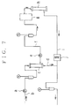
- Cryofiltration will be described with reference to FIG. 7.
- a blood pump a blood is sent from a supply source thereof through a blood supply line b to a primary filter C, which separates the blood into blood cells and plasma.
- the separated blood cells are sent to a blood cell return line d so as to be mixed again with the purified plasma to be described below.
- the plasma is sent by the operation of a plasma pump e from a plasma line f into a secondary filter h for filtration by way of a cooling portion g on the line f.
- the plasma is cooled by the cooling portion g to about 4 C°, and a cryogel of high-molecular-weight substance produced by the cooling is filtered off by the secondary filter and thereby removed from the plasma.
- the filtrate from the secondary filter i.e., purified plasma, is remixed with the blood cells returned from the foregoing primary filter while being returned through a purified plasma return line i.
- the mixture is thereafter returned to the supply source while being heated to the initial liquid temperature by a heating bag j.
- the constant-temperature chamber is difficult to make compact, consequently rendering the overall plasma cryofiltration system large and difficult to move.
- the refrigerant splashes to wet the operator or the neighborhood of the chamber or to expose the system to the refrigerant, causing a malfunction.
- the device which has a low cooling capacity, requires time for cooling plasma to a predetermined temperature and encounters difficulty in maintaining the predetermined temperature. For example, when plasma having a temperature approximate to the body temperature was passed through the bag at a flow rate of about 30 ml/min, it was substantially impossible for the device to cool the plasma to 4 °C. Accordingly, there arises a need to use measures such as larger radiator fins or radiator fans, an increased number of electronic cooling units, a water-cooled radiator portion and a plasma cooling bag having an elongated channel. These measures nevertheless give rise to other problems such as (a) not permitting compaction of the device, (b) an increased cost, (c) difficulty in moving the device, and (d) an increased priming volume. Thus, much still remains to be improved before the actual use of the device.
- U.S. Patent No. 3,399,536 proposes a device wherein electronic cooling units are employed for altering the temperature of blood for use in surgery.
- the proposal entirely differs from the present invention in object and includes no contrivance for ensuring a high cooling capacity for cryofiltration. Accordingly, the device is not usable actually as it is for the plasma cooling bag because the same problems as above will arise.
- the main object of the present invention is to obviate all the foregoing problems (a) to (d) of the coolers comprising electronic cooling units and to provide a compact and efficient cooler of this type.
- the invention provides a cooler for plasma cooling bags which comprises a multiplicity of electronic cooling units dispersedly arranged between a cooling plate and a radiating plate for cooling the plasma cooling bag by the cooling plate and removing heat from the radiating plate by radiating fins provided on the radiating plate and a radiating fan for applying a current of air to the fins, the cooler being characterized in that:
- cooler of the invention will be described with reference to the sketch of FIG. 1 schematically showing the same and based on the vertical sectional view of FIG. 2.
- the cooler of the invention has a cooling plate 1 made of a metal of high thermal conductivity, such as aluminum, and usually about 5 mm in thickness.
- the material and thickness of the plate are not limitative but may be selectively determined suitably.
- the cooling plate 1 is provided on its front side with a receptacle portion 3 into which a plasma cooling bag k can be removably placed when a heat insulating lid 2 is opened.
- the receptacle portion 3 has inside thereof a cooling face la which is provided, for example, with two pairs of right and left bag fastening hooks 4 (see FIG. 1) at upper and lower two portions, respectively, for holding the accommodated bag k generally in face-to-face contact with the cooling face la.
- the bag k is formed at its upper and lower ends with hook engaging holes k1 as positioned in corresponding relation with the respective hooks 4.
- the plasma cooling bag k is flat and flexible and has an elongated zigzag channel l.
- a frame 3a serving as the side wall of the receptacle portion 3 has cutouts 5, 5 for receiving connectors l1, l2 for holding a plasma line f in communication with the inlet and outlet of the channel l of the bag k as accommodated in place. This assures that the connectors l1, l2 provide a plasma passage (not shown) therethrough free of trouble while the heat insulating lid 2 is closed.
- the heat insulating lid 2 can be made up of a body 2a of heat insulating material, and a cover 2b provided over the side periphery and outer surface of the body 2a.
- the lid 2 also serves to press the bag k against the cooling face la to enhance the intimate contact therebetween.
- the external exposed portion of front surface of the cooling plate 1 and the external exposed portion of the frame 3a can be provided with a heat insulating cover.
- Electronic cooling units 6 for absorbing heat from the cooling plate 1 are disposed on the rear side of the plate 1.
- the electronic cooling units 6 operate on the principle of the Peltier effect for electronic cooling and are manufactured and made commercially available by Thermovonics Co., Ltd. of Japan.
- the cooling unit 6 which is commercially available, is in the form of a square measuring about 5 to about 40 mm in the length of one side or a rectangle similar to the square, and has a thickness of about 2.0 to about 4.5 mm.
- a multiplicity of, for example, about 5 to about 15, such electronic cooling units 6 ate dispersedly arranged on the rear side of the cooling plate 1.
- the number of units 6 to be installed and the spacing therebetween are suitably determined, for example, in accordance with the cooling efficiency of the unit 6 and the size of the cooling plate 1.
- Use of a larger number of units naturally results in a higher cooling capacity but also increases the cost of the device itself and power consumption, so that the number of units to be installed is preferably smaller.
- the total of the areas occupied by the electronic cooling units in the region be at least 10%, preferably 10 to 20%, of the area of the cooling plate.
- the cooling plate 1 approximately measures 30 cm (long) x 20 cm (wide).
- Each of the electronic cooling units 6 has a heat absorbing face to which a thermally conductive block 7 is fitted in register therewith.
- the block 7 is in face-to-face contact with the rear surface of the cooling plate 1.
- the block 7 is made of a metal of high thermal conductivity, such as copper, pure silver or aluminum.
- the thickness of the block 7 is determined from such a range that the sum of the thickness and that of the unit 6 is at least 5 mm. When the unit 6 is, for example, 3 mm in thickness, it is suitable that the thickness be about 2 to about 4 mm.
- the block 7 is preferably at least 0.8 cal/cm ⁇ sec ⁇ deg, more preferably 0.9 cal/cm ⁇ sec ⁇ deg, in thermal conductivity.
- the electronic cooling units 6 each have a radiating face in direct face-to-face contact with a radiating plate 8.
- the radiating plate 8 is nearly identical with the cooling plate 1 in shape and size, and opposed to the plate 1 face-to-face in register therewith.
- the radiating plate 8 is provided with radiating fins 9 on its rear side.
- the total radiating area of the radiating fins 9 is at least three times the area of one surface of the cooling plate 1.
- the radiating fins 9 are made of a material of high thermal conductivity.
- the electronic cooling units 6 and the respective blocks 7 superposed thereon serve as spacers between the cooling plate 1 and the radiating plate 8, providing between the two plates 1 and 8 a space 10 of at least 5 mm corresponding to the total thickness of the unit and the block.
- the space 10 includes around the units 6 and the blocks 7 a clearance l0a which is filled with a heat insulating material 11.
- a polyurethane foam having good heat insulating properties is suitable as the heat insulating material 11.
- the heat insulating material 11 is preferably up to 0.03 kcal/m ⁇ hr ⁇ deg, more preferably up to 0.02 kcal/m ⁇ hr ⁇ deg, in thermal conductivity.
- the units 6, blocks 7 and heat insulating material 11 provided in the space 10 are held between the cooling plate 1 and the radiating plate 8 by fasteners, such as bolts and nuts, for fastening the two plates 1, 8 at their end portions.
- fasteners such as bolts and nuts
- Radiating fans 12 are installed on the rear side of the radiating plate 8. Although the radiating fan 12 is disposed at each of upper and lower two locations in the illustrated case, the position and number of fans to be installed are not limited specifically.
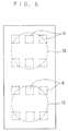
- FIG. 3 shows the relationship between the regions 13, 13 to be exposed to a current of air from the radiating fans 12, 12 and the position of the electronic units 6 installed.
- FIG. 3 shows six units 6 arranged in each region 13 and spaced apart equidistantly circumferentially thereof.
- the region 13 is circular in this case, whereas the region can be square depending on the type of fan insofar as electronic cooling units 6 are arranged in the region 13 to be exposed to a current of air.
- the speed of rotation of the radiating fan 12 is controllable in accordance with the temperature of the cooling plate 1. For example, it is driven at a high speed when starting cooling and slowed down upon the temperature reaching a steady-state level, whereby the power consumption and noise can be diminished.
- a known control method is usable, for example, with use of a temperature sensor provided on the cooling plate 1.
- the space 10 of at least 5 mm is provided between the cooling plate 1 and the radiating plate 8, and the clearance l0a in the space 10 is packed with the heat insulating material 11. This prevents heat transfer between the two plates 1, 8 through the clearance lOa to minimize the heat flow loss. If the space 10 is less than 5 mm, the heat insulating material 11 fails to produce a sufficient heat insulating effect, whereas if the space is conversely excessive, a greatly improved heat insulating effect is not expectable, merely with an increased dimension given to the cooler in the direction of its thickness. To be satisfactory, therefore, the space 10 is about 5 to about 7 mm.
- the electronic cooling units 6 are arranged in the regions 13 to be exposed to a current of air from the radiating fans 12. This assures efficient removal of heat from the radiating side of the units 6 through the radiating plate 8.
- the present invention enables the radiating side of the unit to give off heat efficiently, consequently permitting the electronic cooling element, namely, the unit 6, to retain a high efficiency for a prolonged period of time.
- the present invention minimizes the heat flow loss that would occur between the cooling plate 1 and the radiating plate 8, further permits the electronic cooling units 6 to retain a high efficiency for a prolonged period of time and therefore enables the cooler to exhibit improved performance.
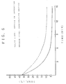
- cooler of the present invention and a comparative cooler shown in FIGS. 4 and 5 were subjected to a cooling efficiency comparative test with the following result.
- like parts are designated by like reference numerals.
- the graph of FIG. 6 reveals that about 9 minutes after the start of cooling, the device of the invention cooled the circulating water to 4 °C, but that the comparative device was unable to cool the water to not higher than 9 °C. Further although the device of the invention maintained a constant cooling temperature, the comparative device exhibited slight temperature variations.
- the cooler of the present invention for plasma cooling bags comprising electronic cooling units as cooling means is so construced as to prevents heat conduction between the radiating side and the cooling side to the greatest possible extent and to fully exhibit the effect of the radiating fans. Consequently, the device can be compacted and is adapted to attain a predetermined temperature in a shortened period of time and to maintain the predetermined temperature with improved stability without entailing an increased cost or an increase in the priming volume due to an elongated plasma channel.
- the present invention is useful especially for cooling plasma cooling bags in practicing cryofiltration.
Landscapes
- Engineering & Computer Science (AREA)
- Health & Medical Sciences (AREA)
- Physics & Mathematics (AREA)
- Heart & Thoracic Surgery (AREA)
- General Engineering & Computer Science (AREA)
- Thermal Sciences (AREA)
- Mechanical Engineering (AREA)
- Anesthesiology (AREA)
- Animal Behavior & Ethology (AREA)
- General Health & Medical Sciences (AREA)
- Public Health (AREA)
- Veterinary Medicine (AREA)
- Life Sciences & Earth Sciences (AREA)
- Hematology (AREA)
- Biomedical Technology (AREA)
- Vascular Medicine (AREA)
- Cooling Or The Like Of Electrical Apparatus (AREA)
- Devices That Are Associated With Refrigeration Equipment (AREA)
Applications Claiming Priority (3)
| Application Number | Priority Date | Filing Date | Title |
|---|---|---|---|
| JP17175993 | 1993-07-12 | ||
| JP171759/93 | 1993-07-12 | ||
| PCT/JP1994/001136 WO1995002425A1 (fr) | 1993-07-12 | 1994-07-12 | Refroidisseur de poches refrigerees de plasma sanguin |
Publications (2)
| Publication Number | Publication Date |
|---|---|
| EP0653215A1 true EP0653215A1 (de) | 1995-05-17 |
| EP0653215A4 EP0653215A4 (de) | 1998-04-22 |
Family
ID=15929159
Family Applications (1)
| Application Number | Title | Priority Date | Filing Date |
|---|---|---|---|
| EP94919891A Withdrawn EP0653215A4 (de) | 1993-07-12 | 1994-07-12 | Kühler für blutplasmakühlbeutel. |
Country Status (5)
| Country | Link |
|---|---|
| EP (1) | EP0653215A4 (de) |
| JP (1) | JP3069797B2 (de) |
| AU (1) | AU672323B2 (de) |
| CA (1) | CA2144442A1 (de) |
| WO (1) | WO1995002425A1 (de) |
Cited By (4)
| Publication number | Priority date | Publication date | Assignee | Title |
|---|---|---|---|---|
| US7776260B2 (en) * | 2006-12-11 | 2010-08-17 | Ethicon, Inc. | Apparatus and method for the irradiation of radiation sensitive materials |
| JP2012235984A (ja) * | 2011-05-13 | 2012-12-06 | Daido Kogyosho:Kk | 血液用冷却装置 |
| US10722623B2 (en) | 2014-08-08 | 2020-07-28 | Fremon Scientific, Inc. | Smart bag used in sensing physiological and/or physical parameters of bags containing biological substance |
| US10732083B2 (en) | 2018-05-07 | 2020-08-04 | Fremon Scientific, Inc. | Thawing biological substances |
Families Citing this family (2)
| Publication number | Priority date | Publication date | Assignee | Title |
|---|---|---|---|---|
| JP5253871B2 (ja) * | 2008-02-26 | 2013-07-31 | 川澄化学工業株式会社 | 血液冷却装置及び採血装置 |
| EP3563886A3 (de) * | 2018-05-03 | 2020-01-22 | Fenwal, Inc. | Optische detektion eines bildes auf einem behälter |
Citations (3)
| Publication number | Priority date | Publication date | Assignee | Title |
|---|---|---|---|---|
| US3293868A (en) * | 1965-02-16 | 1966-12-27 | Medical Electroscience Inc | Fluid cooling apparatus |
| US3399536A (en) * | 1966-02-02 | 1968-09-03 | Siemens Ag | Device for varying the blood temperature |
| US4007600A (en) * | 1975-02-10 | 1977-02-15 | Simms Larry L | Icebox conversion unit |
Family Cites Families (4)
| Publication number | Priority date | Publication date | Assignee | Title |
|---|---|---|---|---|
| US4476685A (en) * | 1981-05-11 | 1984-10-16 | Extracorporeal Medical Specialties, Inc. | Apparatus for heating or cooling fluids |
| FR2505294A1 (fr) * | 1981-05-11 | 1982-11-12 | Extracorporeal Med Spec | Appareil pour chauffer ou refroidir des fluides et recipient utilisable dans cet appareil |
| JPS59164065A (ja) * | 1983-03-07 | 1984-09-17 | 日機装株式会社 | 簡易冷却器 |
| NO160487C (no) * | 1986-11-26 | 1989-04-26 | Fasting Biotech As | Anordning for fjerning av kryoglobuliner. |
-
1994
- 1994-07-12 CA CA002144442A patent/CA2144442A1/en not_active Abandoned
- 1994-07-12 AU AU70852/94A patent/AU672323B2/en not_active Ceased
- 1994-07-12 WO PCT/JP1994/001136 patent/WO1995002425A1/ja not_active Application Discontinuation
- 1994-07-12 JP JP7504466A patent/JP3069797B2/ja not_active Expired - Fee Related
- 1994-07-12 EP EP94919891A patent/EP0653215A4/de not_active Withdrawn
Patent Citations (3)
| Publication number | Priority date | Publication date | Assignee | Title |
|---|---|---|---|---|
| US3293868A (en) * | 1965-02-16 | 1966-12-27 | Medical Electroscience Inc | Fluid cooling apparatus |
| US3399536A (en) * | 1966-02-02 | 1968-09-03 | Siemens Ag | Device for varying the blood temperature |
| US4007600A (en) * | 1975-02-10 | 1977-02-15 | Simms Larry L | Icebox conversion unit |
Non-Patent Citations (1)
| Title |
|---|
| See also references of WO9502425A1 * |
Cited By (8)
| Publication number | Priority date | Publication date | Assignee | Title |
|---|---|---|---|---|
| US7776260B2 (en) * | 2006-12-11 | 2010-08-17 | Ethicon, Inc. | Apparatus and method for the irradiation of radiation sensitive materials |
| JP2012235984A (ja) * | 2011-05-13 | 2012-12-06 | Daido Kogyosho:Kk | 血液用冷却装置 |
| US10722623B2 (en) | 2014-08-08 | 2020-07-28 | Fremon Scientific, Inc. | Smart bag used in sensing physiological and/or physical parameters of bags containing biological substance |
| US10732083B2 (en) | 2018-05-07 | 2020-08-04 | Fremon Scientific, Inc. | Thawing biological substances |
| US10816446B2 (en) | 2018-05-07 | 2020-10-27 | Fremon Scientific, Inc. | Thawing biological substances |
| US10837885B2 (en) | 2018-05-07 | 2020-11-17 | Fremon Scientific, Inc. | Thawing biological substances |
| US10866173B2 (en) | 2018-05-07 | 2020-12-15 | Fremon Scientific, Inc. | Thawing biological substances |
| US11448575B2 (en) | 2018-05-07 | 2022-09-20 | Fremon Scientific, Inc. | Thawing biological substances |
Also Published As
| Publication number | Publication date |
|---|---|
| WO1995002425A1 (fr) | 1995-01-26 |
| AU672323B2 (en) | 1996-09-26 |
| JP3069797B2 (ja) | 2000-07-24 |
| EP0653215A4 (de) | 1998-04-22 |
| AU7085294A (en) | 1995-02-13 |
| CA2144442A1 (en) | 1995-01-26 |
Similar Documents
| Publication | Publication Date | Title |
|---|---|---|
| US5653741A (en) | Heating and cooling pad | |
| JPH1089828A (ja) | 食品貯蔵庫 | |
| EP0338283B1 (de) | Thermoelektrische Kühlvorrichtung | |
| WO2008002652A2 (en) | Apparatus for heating and cooling at food serving stations | |
| EP0653215A1 (de) | Kühler für blutplasmakühlbeutel | |
| JP2001024240A (ja) | 温度調整装置 | |
| JP2500902Y2 (ja) | ラジエ―タ型暖房機 | |
| KR20050018518A (ko) | 전기자동차용 배터리 트레이 냉각장치 | |
| JP3321624B2 (ja) | 冷却装置 | |
| KR200272893Y1 (ko) | 냉온겸용침대매트열교환장치 | |
| JP3660369B2 (ja) | 恒温槽の液体温度調節装置 | |
| JP3013248B1 (ja) | 水槽水の濾過冷却装置 | |
| KR920007157Y1 (ko) | 냉온 소자를 이용한 한쌍의 보온, 보냉용기 | |
| JP3920393B2 (ja) | 保温・保冷具 | |
| JPH09220251A (ja) | 冷加熱装置 | |
| CN217274941U (zh) | 温度调节装置及护理设备 | |
| JPH0536412Y2 (de) | ||
| JP3060506B2 (ja) | 冷却機能付浄水器 | |
| JPH09201380A (ja) | 患部冷却装置 | |
| SE9100989D0 (sv) | Vaermelagrande vaermeapparat | |
| JPH09276315A (ja) | 電子温冷治療装置 | |
| WO1998023235A1 (fr) | Tube thermo-isolant et revetement thermo-isolant | |
| JPH04313689A (ja) | 蓄熱装置 | |
| SU1759351A1 (ru) | Устройство дл тепловой обработки пчел | |
| JP3318939B2 (ja) | 精米前処理装置 |
Legal Events
| Date | Code | Title | Description |
|---|---|---|---|
| PUAI | Public reference made under article 153(3) epc to a published international application that has entered the european phase |
Free format text: ORIGINAL CODE: 0009012 |
|
| 17P | Request for examination filed |
Effective date: 19950307 |
|
| AK | Designated contracting states |
Kind code of ref document: A1 Designated state(s): AT BE CH DE DK ES FR GB GR IE IT LI LU MC NL PT SE |
|
| A4 | Supplementary search report drawn up and despatched |
Effective date: 19980303 |
|
| AK | Designated contracting states |
Kind code of ref document: A4 Designated state(s): AT BE CH DE DK ES FR GB GR IE IT LI LU MC NL PT SE |
|
| STAA | Information on the status of an ep patent application or granted ep patent |
Free format text: STATUS: THE APPLICATION IS DEEMED TO BE WITHDRAWN |
|
| 18D | Application deemed to be withdrawn |
Effective date: 19950413 |