EP0651484B1 - Hochspannungsschaltgerät - Google Patents
Hochspannungsschaltgerät Download PDFInfo
- Publication number
- EP0651484B1 EP0651484B1 EP94115815A EP94115815A EP0651484B1 EP 0651484 B1 EP0651484 B1 EP 0651484B1 EP 94115815 A EP94115815 A EP 94115815A EP 94115815 A EP94115815 A EP 94115815A EP 0651484 B1 EP0651484 B1 EP 0651484B1
- Authority
- EP
- European Patent Office
- Prior art keywords
- housing
- middle section
- angle
- switching device
- switching points
- Prior art date
- Legal status (The legal status is an assumption and is not a legal conclusion. Google has not performed a legal analysis and makes no representation as to the accuracy of the status listed.)
- Expired - Lifetime
Links
- 239000002184 metal Substances 0.000 claims description 7
- 230000008901 benefit Effects 0.000 description 4
- 238000010791 quenching Methods 0.000 description 4
- 230000000171 quenching effect Effects 0.000 description 4
- 238000009434 installation Methods 0.000 description 2
- 230000004308 accommodation Effects 0.000 description 1
- 230000000694 effects Effects 0.000 description 1
- 230000002996 emotional effect Effects 0.000 description 1
- 239000012212 insulator Substances 0.000 description 1
Images

Classifications
-
- H—ELECTRICITY
- H02—GENERATION; CONVERSION OR DISTRIBUTION OF ELECTRIC POWER
- H02B—BOARDS, SUBSTATIONS OR SWITCHING ARRANGEMENTS FOR THE SUPPLY OR DISTRIBUTION OF ELECTRIC POWER
- H02B13/00—Arrangement of switchgear in which switches are enclosed in, or structurally associated with, a casing, e.g. cubicle
- H02B13/02—Arrangement of switchgear in which switches are enclosed in, or structurally associated with, a casing, e.g. cubicle with metal casing
- H02B13/035—Gas-insulated switchgear
- H02B13/0356—Mounting of monitoring devices, e.g. current transformers
-
- H—ELECTRICITY
- H01—ELECTRIC ELEMENTS
- H01H—ELECTRIC SWITCHES; RELAYS; SELECTORS; EMERGENCY PROTECTIVE DEVICES
- H01H33/00—High-tension or heavy-current switches with arc-extinguishing or arc-preventing means
- H01H33/02—Details
- H01H33/04—Means for extinguishing or preventing arc between current-carrying parts
- H01H33/16—Impedances connected with contacts
Definitions
- the invention is based on a high-voltage switching device for a gas-insulated switchgear according to the generic term of claim 1.
- high-voltage switchgear for gas-insulated switchgear known, for example from the patent DE 25 38 130, which have two switching points along one common longitudinal axis extends. The two switching points are operated by a common drive, the centrally in the middle between the two switching points attacks. If the high-voltage switchgear is installed horizontally, so it requires a comparatively large footprint for the two elongated switching points. Becomes the high-voltage switching device is set up with a vertical longitudinal axis, so it needs a lot more upwards Space that cannot be used otherwise.
- the invention as in the independent claim is characterized, solves the task a high-voltage switching device for a gas-insulated To create switchgear, which is both horizontal and takes up less space even when installed vertically.
- a preferred embodiment of the high-voltage switching device for a gas-insulated switchgear has a gas-filled one Metal case and one held in it Current path on itself, at least two in series has switched switching points.
- the moving contact pieces of the switching points are from a common one the drive attached to the metal housing.
- the Current path forms an angle, with on each leg of the Angle at least one of the at least two switching points is arranged, and wherein the angle is designed as a right angle.
- the metal housing of the high-voltage switching device has one Middle section on the two tubular housing sections are scheduled, of which at least one each encloses one of the switching points, the Longitudinal axes of the tubular housing sections parallel to The axis of the respective leg runs. The vertex of the The angle is always within the middle section.
- the middle section has at least one first opening, those for the installation of the moving contact pieces Drive is provided.
- the middle section points also a second Opening on that for mounting a resistance housing is provided, which one when switching on the switch-on resistance in operative connection and auxiliary switching points necessary for switching it on and off encloses.
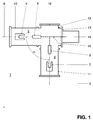
- the high-voltage switching device 1 shows a simplified first embodiment of a high-voltage switching device for a gas-insulated Switchgear. With this high-voltage switching device, it can a circuit breaker or one Act separator.
- the high-voltage switching device 1 has two switching points 2,3 connected in series.
- the switching point 2 has a fixed contact piece 4 and a movable one Contact piece 5, which is in the direction of a first Longitudinal axis 6 moves.
- the switching point 3 has a fixed one Contact piece 7 and a movable contact piece 8 on which is in the direction of a second longitudinal axis 9 emotional.
- the switching points 2, 3 are tubular Housings 10,11 arranged.
- the two tubular housings 10 and 11 have a corner housing 12 connected pressure-tight.
- the corner housing 12 can also on one the housing 10 or 11 can be cast on.
- Housings 10 and 11 are on the corner housing 12 other side of the gas-insulated components Switchgear connected pressure-tight, however are not shown here.
- the two longitudinal axes 6 and 9 intersect at an angle ⁇ that is 90 °.
- the corner housing 12 is provided with a first opening 13, which is closed with a flange to which a drive 14 is flanged.
- the drive 14 acts as one branching, dashed line of action 15 indicates the two movable contact pieces 5 and 8 and moves them in the switch-off or switch-on direction.
- the corner housing 12 is provided with a second opening 16 with a flange is closed pressure-tight.
- FIG. 2 shows a simplified second embodiment of a high-voltage switching device for a gas-insulated Switchgear.
- a high-voltage switching device for example act as a circuit breaker with on-resistance is equipped.
- This high-voltage switching device is a pressure-tight at the opening 16
- Resistor housing 17 flanged.
- This resistance housing 17 encloses an on resistor 18 and here Auxiliary switching points, not shown, which are and shutdown are necessary.
- the actuation of the auxiliary switching points takes place, as indicated by an action line 19, from the drive 14.
- the on-resistance 18 bridges before switching on one by separating the not shown Disconnection point and then after switching on by closing it Disconnection point short-circuited. Another auxiliary switching point then disconnects the on-resistance 18.
- the angled design of the high-voltage switching device enables more compact system configurations for gas-insulated Switchgear.
- Such system configurations allow the Creation of smaller buildings for the accommodation of the gas-insulated switchgear, what its cost-effectiveness advantageously increased.
Landscapes
- Engineering & Computer Science (AREA)
- Power Engineering (AREA)
- Gas-Insulated Switchgears (AREA)
- Arc-Extinguishing Devices That Are Switches (AREA)
- Driving Mechanisms And Operating Circuits Of Arc-Extinguishing High-Tension Switches (AREA)
Description
- 1
- Hochspannungsschaltgerät
- 2,3
- Schaltstellen
- 4
- feststehendes Kontaktstück
- 5
- bewegliches Kontaktstück
- 6
- Längsachse
- 7
- feststehendes Kontaktstück
- 8
- bewegliches Kontaktstück
- 9
- Längsachse
- 10,11
- Gehäuse
- 12
- Eckgehäuse
- 13
- Öffnung
- 14
- Antrieb
- 15
- Wirkungslinie
- 16
- Öffnung
- 17
- Widerstandsgehäuse
- 18
- Einschaltwiderstand
- 19
- Wirkungslinie
- α
- Winkel
Claims (4)
- Hochspannungsschaltgerät für eine metallgekapselte gasisolierte Schaltanlage mit einem gasgefüllten, einen Mittelabschnitt aufweisenden Metallgehäuse und mit einer in diesem gehaltenen Strombahn, die mindestens zwei in Reihe geschaltete Schaltstellen (2,3) aufweist, deren bewegliche Kontaktstücke (5,8) von einem gemeinsamen, an einer ersten Öffnung (13) des Mittelabschnitts des Metallgehäuses befestigten Antrieb (14) betätigt werden, wobei die Strombahn einen Winkel (α) bildet, und wobei auf jedem Schenkel des Winkels (α) jeweils mindestens eine der mindestens zwei Schaltstellen (2,3) angeordnet ist, deren jede von einem rohrförmigen, an den Mittelabschnitt angesetzten Gehäuseabschnitt umschlossen ist, und wobei der Mittelabschnitt eine zweite Öffnung (16) aufweist, die für den Anbau eines Widerstandsgehäuses (17) vorgesehen ist, welches einen beim Einschalten mit den Schaltstellen (2,3) in Wirkverbindung stehenden Einschaltwiderstand (18) und für dessen Zu- und Abschaltung nötige Hilfsschaltstellen umschliesst, dadurch gekennzeichnet,dass der Winkel (α) als rechter Winkel ausgebildet ist.
- Hochspannungsschaltgerät nach Anspruch 1, dadurch gekennzeichnet,dass die Längsachsen (6,9) der rohrförmigen Gehäuseabschnitte parallel zur Achse des jeweiligen Schenkels verlaufen.
- Hochspannungsschaltgerät nach einem der Ansprüche 1 oder 2, dadurch gekennzeichnet,dass der Scheitel des Winkels (α) innerhalb des Mittelabschnitts liegt.
- Hochspannungsschaltgerät nach einem der Ansprüche 1 bis 3, dadurch gekennzeichnet,dass der Mittelabschnitt als Eckgehäuse (12) mit Anschlussflanschen ausgebildet ist, mit denen die rohrförmigen Gehäuseabschnitte druckdicht verbunden werden.
Applications Claiming Priority (2)
| Application Number | Priority Date | Filing Date | Title |
|---|---|---|---|
| DE4336951A DE4336951A1 (de) | 1993-10-29 | 1993-10-29 | Hochspannungsschaltgerät |
| DE4336951 | 1993-10-29 |
Publications (2)
| Publication Number | Publication Date |
|---|---|
| EP0651484A1 EP0651484A1 (de) | 1995-05-03 |
| EP0651484B1 true EP0651484B1 (de) | 1998-09-02 |
Family
ID=6501327
Family Applications (1)
| Application Number | Title | Priority Date | Filing Date |
|---|---|---|---|
| EP94115815A Expired - Lifetime EP0651484B1 (de) | 1993-10-29 | 1994-10-07 | Hochspannungsschaltgerät |
Country Status (4)
| Country | Link |
|---|---|
| US (1) | US5484972A (de) |
| EP (1) | EP0651484B1 (de) |
| CA (1) | CA2131469A1 (de) |
| DE (2) | DE4336951A1 (de) |
Families Citing this family (12)
| Publication number | Priority date | Publication date | Assignee | Title |
|---|---|---|---|---|
| EP0678952B1 (de) * | 1994-04-19 | 1998-08-26 | Asea Brown Boveri Ag | Trenner für eine metallgekapselte gasisolierte Hochspannungsschaltanlage |
| DE4420524A1 (de) * | 1994-06-13 | 1995-12-14 | Abb Management Ag | Metallgekapselte gasisolierte Schaltanlage |
| JP3240849B2 (ja) * | 1994-08-31 | 2001-12-25 | 株式会社日立製作所 | ガス絶縁開閉装置 |
| DE19511168A1 (de) * | 1995-03-28 | 1996-10-02 | Abb Management Ag | Schaltvorrichtung |
| DE19519301A1 (de) * | 1995-05-26 | 1996-11-28 | Abb Management Ag | Trenner für eine metallgekapselte gasisolierte Hochspannungsschaltanlage |
| DE19615912A1 (de) * | 1996-04-22 | 1997-10-23 | Asea Brown Boveri | Trennschalter |
| CN1697274A (zh) * | 1998-10-13 | 2005-11-16 | 株式会社日立制作所 | 气体绝缘开关装置 |
| US6723939B2 (en) | 2002-09-11 | 2004-04-20 | Eaton Corporation | Isolation switch for electric power systems |
| CN1830123B (zh) * | 2003-08-07 | 2012-02-08 | 阿雷瓦输配电公司 | 具有三个开关位置的接地开关 |
| TW200835105A (en) * | 2007-02-08 | 2008-08-16 | Hitachi Ltd | DC switchgear provided with a commutation-type DC circuit breaker |
| KR101786522B1 (ko) * | 2014-08-07 | 2017-10-18 | 엘에스산전 주식회사 | 차단기용 투입저항유닛의 지지구조 |
| DE102018205910A1 (de) | 2018-04-18 | 2019-10-24 | Siemens Aktiengesellschaft | Hochspannungsleistungsschalter mit Einschaltwiderstandsanordnung sowie Koppeleinrichtung |
Family Cites Families (20)
| Publication number | Priority date | Publication date | Assignee | Title |
|---|---|---|---|---|
| DE50657C (de) * | A. B. FERDINAND in Oshkosh, 93 Jefferson Avenue, Coun.ty Winnebago, Wisconsin, V. St. A | Neuerungen an elektrischen Schallvorrichtungen für Telephone, Telegraphen, Signalapparate und dergleichen | ||
| DE914404C (de) * | 1951-07-11 | 1954-07-01 | Siemens Ag | Fluessigkeitsarmer Leistungsschalter |
| US2965735A (en) * | 1956-06-07 | 1960-12-20 | Westinghouse Electric Corp | Compressed-gas circuit interrupter |
| NL134084C (de) * | 1967-04-06 | |||
| DE1615835A1 (de) * | 1967-04-06 | 1971-09-09 | Bbc Brown Boveri & Cie | Trennvorrichtung fuer vollisolierte elektrische Hochspannungs-Schaltanlagen |
| GB1507024A (en) * | 1974-04-09 | 1978-04-12 | Reyrolle Parsons Ltd | Circuit-breakers |
| NL158330B (nl) * | 1975-02-13 | 1978-10-16 | Coq Bv | Geheel gesloten eenfase schakeldveld voor hoge spanning. |
| DE2538130C2 (de) * | 1975-08-25 | 1985-03-28 | Siemens AG, 1000 Berlin und 8000 München | Hochspannungsschalter |
| CH619559A5 (en) * | 1977-09-28 | 1980-09-30 | Sprecher & Schuh Ag | Compressed-gas high-voltage switch for outdoor installation |
| CH615295A5 (en) * | 1978-01-18 | 1980-01-15 | Sprecher & Schuh Ag | Gas blast circuit breaker |
| CH622375A5 (en) * | 1978-01-20 | 1981-03-31 | Sprecher & Schuh Ag | High-voltage multiple-break circuit-breaker |
| DE2817417A1 (de) * | 1978-04-18 | 1979-10-25 | Krone Gmbh | Gas- oder fluessigkeitsisolierte mittelspannungs-schaltanlage, insbesondere fuer spannungen von 1 bis 36 kv |
| JPS5576526A (en) * | 1978-12-01 | 1980-06-09 | Hitachi Ltd | Gas breaker |
| JPS5769633A (en) * | 1980-10-20 | 1982-04-28 | Hitachi Ltd | Resistance breakdown gas breaker |
| US4379957A (en) * | 1981-01-14 | 1983-04-12 | Westinghouse Electric Corp. | Modular "Y"-type enclosure elements for gas insulated substations |
| JPS5840715A (ja) * | 1981-09-04 | 1983-03-09 | 株式会社東芝 | しや断器 |
| US4463229A (en) * | 1981-11-13 | 1984-07-31 | Westinghouse Electric Corp. | Pneumatic operating mechanism for a circuit breaker |
| US4510359A (en) * | 1983-11-08 | 1985-04-09 | Westinghouse Electric Corp. | Circuit interrupter having improved closing resistor control means |
| DE3413962A1 (de) * | 1984-02-23 | 1985-08-29 | BBC Aktiengesellschaft Brown, Boveri & Cie., Baden, Aargau | Hochspannungsschalter |
| DE3521945A1 (de) * | 1985-06-14 | 1986-12-18 | Siemens AG, 1000 Berlin und 8000 München | Trennschalter fuer eine metallgekapselte, druckgasisolierte hochspannungsschaltanlage |
-
1993
- 1993-10-29 DE DE4336951A patent/DE4336951A1/de not_active Withdrawn
-
1994
- 1994-09-06 CA CA002131469A patent/CA2131469A1/en not_active Abandoned
- 1994-09-19 US US08/307,427 patent/US5484972A/en not_active Expired - Fee Related
- 1994-10-07 DE DE59406822T patent/DE59406822D1/de not_active Expired - Fee Related
- 1994-10-07 EP EP94115815A patent/EP0651484B1/de not_active Expired - Lifetime
Also Published As
| Publication number | Publication date |
|---|---|
| DE4336951A1 (de) | 1995-05-04 |
| EP0651484A1 (de) | 1995-05-03 |
| US5484972A (en) | 1996-01-16 |
| DE59406822D1 (de) | 1998-10-08 |
| CA2131469A1 (en) | 1995-04-30 |
Similar Documents
| Publication | Publication Date | Title |
|---|---|---|
| DE69602200T2 (de) | Hybrid-hochspannungsschalter | |
| EP0688071B2 (de) | Metallgekapselte gasisolierte Schaltanlage | |
| DE19716024B4 (de) | Metallgekapselte gasisolierte Schaltanlage | |
| EP0735637A2 (de) | Schaltvorrichtung mit einem geerdeten, isoliergasgefüllten Metallgehäuse | |
| EP1082791B1 (de) | Kombinierter trenn-erdungsschalter zum einbau in einen kapselungsbaustein einer gasisolierten schaltanlage und kapselungsbaustein mit einem eingebauten kombinierten trenn-erdungs-schalter | |
| WO2005083859A1 (de) | Gekapselte gasisolierte schaltanlage | |
| EP0651484B1 (de) | Hochspannungsschaltgerät | |
| EP0069693B1 (de) | Zylindrischer Behölter für eine dreipolige metallgekapselte, druckgasisolierte Hochspannungsschaltanlage | |
| DE2037234A1 (de) | Schaltgerat für hohe Spannungen | |
| DE69323160T2 (de) | Öffnungs- und Schliessmechanismus für einen elektrischen Mittel- oder Hochspannungsschalter | |
| EP0678954A1 (de) | Metallgekapselte gasisolierte Schaltanlage | |
| EP0678952B1 (de) | Trenner für eine metallgekapselte gasisolierte Hochspannungsschaltanlage | |
| EP0563803B1 (de) | Hochspannungsschaltfeld | |
| EP1249910A2 (de) | Hochspannungs-Leistungsschalter für eine druckgasisolierte Schaltanlage | |
| EP0205397B1 (de) | Trennschalter für eine metallgekapselte, druckgasisolierte Hochspannungsschaltanlage | |
| DE3436173A1 (de) | Schaltanlage | |
| EP0796502B1 (de) | Metallgekapselte schaltanlage mit einem vakuumschaltgerät | |
| DE2907559C2 (de) | Dreipoliger Hochspannungsschalter insbesondere Lasttrenner | |
| DE3334682A1 (de) | Metallgekapselte, gasisolierte hochspannungsleitung | |
| DE3318229A1 (de) | Gehaeuse fuer hochspannungsschalter | |
| DE4210545A1 (de) | Trennschalter für eine metallgekapselte gasisolierte Hochspannungsanlage | |
| EP0054726A2 (de) | Anordnung zur Erdung der stromführenden Teile einer gekapselten Schaltanlage und zur Prüfung der an die Schaltanlage angeschlossenen Kabel | |
| DE4306579C2 (de) | Gasisolierter Trennschalter | |
| DE2847376C2 (de) | Ein- oder mehrpolige Trennschalteranordnung für gekapselte Schaltanlagen | |
| DE4319378A1 (de) | Ortsfest aufstellbarer Druckgas-Hochspannungs-Leistungsschalter mit Tragefunktion für gasisolierte Schaltanlagenkomponenten |
Legal Events
| Date | Code | Title | Description |
|---|---|---|---|
| PUAI | Public reference made under article 153(3) epc to a published international application that has entered the european phase |
Free format text: ORIGINAL CODE: 0009012 |
|
| AK | Designated contracting states |
Kind code of ref document: A1 Designated state(s): CH DE FR LI |
|
| 17P | Request for examination filed |
Effective date: 19951006 |
|
| RAP1 | Party data changed (applicant data changed or rights of an application transferred) |
Owner name: ASEA BROWN BOVERI AG |
|
| 17Q | First examination report despatched |
Effective date: 19970314 |
|
| GRAG | Despatch of communication of intention to grant |
Free format text: ORIGINAL CODE: EPIDOS AGRA |
|
| GRAG | Despatch of communication of intention to grant |
Free format text: ORIGINAL CODE: EPIDOS AGRA |
|
| GRAH | Despatch of communication of intention to grant a patent |
Free format text: ORIGINAL CODE: EPIDOS IGRA |
|
| GRAH | Despatch of communication of intention to grant a patent |
Free format text: ORIGINAL CODE: EPIDOS IGRA |
|
| GRAA | (expected) grant |
Free format text: ORIGINAL CODE: 0009210 |
|
| AK | Designated contracting states |
Kind code of ref document: B1 Designated state(s): CH DE FR LI |
|
| REG | Reference to a national code |
Ref country code: CH Ref legal event code: EP |
|
| REF | Corresponds to: |
Ref document number: 59406822 Country of ref document: DE Date of ref document: 19981008 |
|
| ET | Fr: translation filed | ||
| PLBE | No opposition filed within time limit |
Free format text: ORIGINAL CODE: 0009261 |
|
| STAA | Information on the status of an ep patent application or granted ep patent |
Free format text: STATUS: NO OPPOSITION FILED WITHIN TIME LIMIT |
|
| 26N | No opposition filed | ||
| REG | Reference to a national code |
Ref country code: CH Ref legal event code: PFA Free format text: ASEA BROWN BOVERI AG TRANSFER- ABB SCHWEIZ HOLDING AG Ref country code: CH Ref legal event code: NV Representative=s name: ABB SCHWEIZ AG INTELLECTUAL PROPERTY (CH-LC/IP) |
|
| REG | Reference to a national code |
Ref country code: FR Ref legal event code: CD Ref country code: FR Ref legal event code: CA |
|
| PGFP | Annual fee paid to national office [announced via postgrant information from national office to epo] |
Ref country code: DE Payment date: 20041008 Year of fee payment: 11 |
|
| PGFP | Annual fee paid to national office [announced via postgrant information from national office to epo] |
Ref country code: CH Payment date: 20041011 Year of fee payment: 11 |
|
| PGFP | Annual fee paid to national office [announced via postgrant information from national office to epo] |
Ref country code: FR Payment date: 20041012 Year of fee payment: 11 |
|
| REG | Reference to a national code |
Ref country code: CH Ref legal event code: PUE Owner name: ABB SCHWEIZ AG Free format text: ABB SCHWEIZ HOLDING AG#BROWN BOVERI STRASSE 6#5400 BADEN (CH) -TRANSFER TO- ABB SCHWEIZ AG#BROWN BOVERI STRASSE 6#5400 BADEN (CH) |
|
| REG | Reference to a national code |
Ref country code: FR Ref legal event code: TP |
|
| PG25 | Lapsed in a contracting state [announced via postgrant information from national office to epo] |
Ref country code: LI Free format text: LAPSE BECAUSE OF NON-PAYMENT OF DUE FEES Effective date: 20051031 Ref country code: CH Free format text: LAPSE BECAUSE OF NON-PAYMENT OF DUE FEES Effective date: 20051031 |
|
| PG25 | Lapsed in a contracting state [announced via postgrant information from national office to epo] |
Ref country code: DE Free format text: LAPSE BECAUSE OF NON-PAYMENT OF DUE FEES Effective date: 20060503 |
|
| REG | Reference to a national code |
Ref country code: CH Ref legal event code: PL |
|
| PG25 | Lapsed in a contracting state [announced via postgrant information from national office to epo] |
Ref country code: FR Free format text: LAPSE BECAUSE OF NON-PAYMENT OF DUE FEES Effective date: 20060630 |
|
| REG | Reference to a national code |
Ref country code: FR Ref legal event code: ST Effective date: 20060630 |