EP0651103A1 - Wandisolierung und ein Kunststoffprofilsystem dafür - Google Patents
Wandisolierung und ein Kunststoffprofilsystem dafür Download PDFInfo
- Publication number
- EP0651103A1 EP0651103A1 EP94203173A EP94203173A EP0651103A1 EP 0651103 A1 EP0651103 A1 EP 0651103A1 EP 94203173 A EP94203173 A EP 94203173A EP 94203173 A EP94203173 A EP 94203173A EP 0651103 A1 EP0651103 A1 EP 0651103A1
- Authority
- EP
- European Patent Office
- Prior art keywords
- profile
- edge
- wall insulation
- socle
- wall
- Prior art date
- Legal status (The legal status is an assumption and is not a legal conclusion. Google has not performed a legal analysis and makes no representation as to the accuracy of the status listed.)
- Withdrawn
Links
- 238000009413 insulation Methods 0.000 title claims abstract description 26
- 239000004033 plastic Substances 0.000 title claims abstract description 21
- 239000000463 material Substances 0.000 claims abstract description 46
- 239000011248 coating agent Substances 0.000 claims abstract description 24
- 238000000576 coating method Methods 0.000 claims abstract description 24
- 230000008878 coupling Effects 0.000 claims abstract description 14
- 238000010168 coupling process Methods 0.000 claims abstract description 14
- 238000005859 coupling reaction Methods 0.000 claims abstract description 14
- 239000012528 membrane Substances 0.000 claims description 8
- 230000001681 protective effect Effects 0.000 claims description 3
- 238000007688 edging Methods 0.000 claims description 2
- 239000010410 layer Substances 0.000 description 5
- 239000004570 mortar (masonry) Substances 0.000 description 4
- 230000000007 visual effect Effects 0.000 description 4
- 238000010276 construction Methods 0.000 description 3
- 239000011247 coating layer Substances 0.000 description 2
- 229910052500 inorganic mineral Inorganic materials 0.000 description 2
- 239000011707 mineral Substances 0.000 description 2
- 239000011490 mineral wool Substances 0.000 description 2
- 239000004793 Polystyrene Substances 0.000 description 1
- 238000004873 anchoring Methods 0.000 description 1
- 238000005452 bending Methods 0.000 description 1
- 230000007797 corrosion Effects 0.000 description 1
- 238000005260 corrosion Methods 0.000 description 1
- 239000004794 expanded polystyrene Substances 0.000 description 1
- 239000011810 insulating material Substances 0.000 description 1
- 239000012774 insulation material Substances 0.000 description 1
- 238000005192 partition Methods 0.000 description 1
- 229920002223 polystyrene Polymers 0.000 description 1
- 230000000717 retained effect Effects 0.000 description 1
- 230000007704 transition Effects 0.000 description 1
Images


Classifications
-
- E—FIXED CONSTRUCTIONS
- E04—BUILDING
- E04B—GENERAL BUILDING CONSTRUCTIONS; WALLS, e.g. PARTITIONS; ROOFS; FLOORS; CEILINGS; INSULATION OR OTHER PROTECTION OF BUILDINGS
- E04B1/00—Constructions in general; Structures which are not restricted either to walls, e.g. partitions, or floors or ceilings or roofs
- E04B1/62—Insulation or other protection; Elements or use of specified material therefor
- E04B1/74—Heat, sound or noise insulation, absorption, or reflection; Other building methods affording favourable thermal or acoustical conditions, e.g. accumulating of heat within walls
- E04B1/76—Heat, sound or noise insulation, absorption, or reflection; Other building methods affording favourable thermal or acoustical conditions, e.g. accumulating of heat within walls specifically with respect to heat only
- E04B1/762—Exterior insulation of exterior walls
- E04B1/765—Bottom edge finishing profile
-
- E—FIXED CONSTRUCTIONS
- E04—BUILDING
- E04B—GENERAL BUILDING CONSTRUCTIONS; WALLS, e.g. PARTITIONS; ROOFS; FLOORS; CEILINGS; INSULATION OR OTHER PROTECTION OF BUILDINGS
- E04B1/00—Constructions in general; Structures which are not restricted either to walls, e.g. partitions, or floors or ceilings or roofs
- E04B1/62—Insulation or other protection; Elements or use of specified material therefor
- E04B1/74—Heat, sound or noise insulation, absorption, or reflection; Other building methods affording favourable thermal or acoustical conditions, e.g. accumulating of heat within walls
- E04B1/76—Heat, sound or noise insulation, absorption, or reflection; Other building methods affording favourable thermal or acoustical conditions, e.g. accumulating of heat within walls specifically with respect to heat only
- E04B1/762—Exterior insulation of exterior walls
-
- E—FIXED CONSTRUCTIONS
- E04—BUILDING
- E04F—FINISHING WORK ON BUILDINGS, e.g. STAIRS, FLOORS
- E04F13/00—Coverings or linings, e.g. for walls or ceilings
- E04F13/02—Coverings or linings, e.g. for walls or ceilings of plastic materials hardening after applying, e.g. plaster
- E04F13/04—Bases for plaster
- E04F13/06—Edge-protecting borders
- E04F2013/063—Edge-protecting borders for corners
-
- E—FIXED CONSTRUCTIONS
- E04—BUILDING
- E04F—FINISHING WORK ON BUILDINGS, e.g. STAIRS, FLOORS
- E04F13/00—Coverings or linings, e.g. for walls or ceilings
- E04F13/02—Coverings or linings, e.g. for walls or ceilings of plastic materials hardening after applying, e.g. plaster
- E04F13/04—Bases for plaster
- E04F13/06—Edge-protecting borders
- E04F2013/065—Edge-protecting borders for lower edges of outer insulation layers
-
- E—FIXED CONSTRUCTIONS
- E04—BUILDING
- E04F—FINISHING WORK ON BUILDINGS, e.g. STAIRS, FLOORS
- E04F13/00—Coverings or linings, e.g. for walls or ceilings
- E04F13/02—Coverings or linings, e.g. for walls or ceilings of plastic materials hardening after applying, e.g. plaster
- E04F13/04—Bases for plaster
- E04F13/06—Edge-protecting borders
- E04F2013/066—Edge-protecting borders for expansion joints between two plaster layers
Definitions
- the present invention relates to a wall insulation and to a plastic profile system therefor.
- the present invention relates more in particular to a wall insulation wherein insulating plate-like materials such as of polystyrene and mineral wool are arranged on the wall with this plastic profile system. In the case of a building this can take place on the inside and on the outside.
- the present invention has for its object to provide a wall insulation and a profile system therefor which substantially does not display the above stated drawbacks.
- a wall insulation according to the invention for insulating a wall with a plastic profile system comprising insulating plate-like material, which profile system comprises: a plastic socle profile for fixing to the wall, and a plastic edge profile which is provided with a closing edge for enclosing the plate material and with a supporting edge for receiving coating material to be arranged on the plate material, wherein the socle profile and the edge profile are provided with co-acting coupling means.
- the wall insulation according to the invention can be continuously adapted to the thicker or thinner coating material for use, while corrosion problems substantially do not occur.
- the socle profile is provided with a free leg standing away from the wall having at least one hooking edge comprised by the coupling means and behind which hooks an edging profile edge.
- the socle profile is provided with two hooking edges and the profile with two co-acting socle profile hooking edges.
- a first socle profile hooking edge is formed in the surface of the free leg. It is thus possible to form the socle profile hooking edge in the surface directed toward the insulating plate-like material or toward the usually bottom surface remote therefrom. An optimum choice can be made in accordance with the application.
- a second socle profile hooking edge is preferably formed on the free end of the socle profile leg.
- the closing edge stands on a base which connects onto the free leg.
- the supporting edge connects onto the base with the forming of a channel open to the side.
- An optimum construction is obtained if in further preference the base is provided with the first edge profile hooking edge and the supporting edge with the second edge profile hooking edge.
- the membrane is provided with a removable protective strip.
- the transition between two plate-like materials standing in particular at an angle can be spanned in optimal manner while the coating material can be arranged quickly and simply if in further preference plates of material standing at an angle are connected by a corner profile having legs standing at an angle fixed to the plates or the wall and a corner edge extending through the coating material.
- the angle is preferably smaller than 90° so that angles larger than and beyond 90° can be spanned simply by bending the legs outward.
- the present invention relates to the plastic profile system per se which comprises a plastic socle profile, a plastic edge profile, a plastic expansion profile and a plastic corner profile, the construction of which is described above.
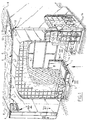
- FIGS 1-3 show a wall insulation 1 according to the invention for an outside wall 2 of a building.
- the wall insulation 1 comprises a plastic profile system 3 comprising a socle profile 4 with an edge profile 5 coupled thereto by hooks, in addition to an expansion profile 6 and a corner profile 7.
- this profile system plate-like insulation material such as plates 8 of flame-extinguishing, expanded polystyrene i or mineral wool is fixed to the wall 2.
- These plates 8 are provided with a coating layer 9 which consists of a dense earth mortar having embedded therein a pressure-distributing, mesh-like layer 11 and a visual mortar 12 of relatively open structure.
- the wall insulation can be arranged below ground level but can also extend only above ground level in the case for instance a ground floor does not have to be insulated.
- FIG. 2 shows in more detail the coupling between socle profile 4 and edge profile 5.
- Socle profile 4 is arranged in the wall 2 with a screw 13 and rests in the ground 14.
- Socle profile 4 comprises a leg 15, which is fixed with screw 13 to the wall 2, and a free leg 16.
- the latter is provided with the coupling means 17.
- These coupling means 17 comprise a first hooking edge 18 which is formed in the surface 19 of the free leg 16 and a second hooking edge 20 formed on the free end 21 of the leg 16.
- a channel 22 open to the top in which the edge profile 5 will engage with corresponding coupling means 17.
- the edge profile 5 comprises a closing edge 23, with which the plate material 8 is enclosed, and a supporting edge 24 for receiving coating material, both earth mortar and visual mortar and the mesh layer 11.
- the supporting edge 24 ends in a guide edge 25 so that the coating material 12 can be spread smoothly.
- the closing edge 23 stands on a base 26 which connects onto the free leg 16 of socle profile 4.
- Supporting edge 24 is connected via a partition 27 to the base 26 and therein forms a channel 28 open to the side which is filled with coating material 10, 12 and the mesh layer 11, whereby a very adequate support and protection is obtained.
- Base 26 is further provided with a hooking edge 29 which co-acts with hooking edge 18 of the socle profile and further a hooking edge 30 which co-acts with hooking edge 20 of the socle profile.
- the hooking edge 29 herein lies in the channel 22.
- the coupling between socle profile 4 and edge profile 5 is effected by hooking on edge profile 5 from below as according to arrow 31.
- edge profile 5 is hooked on by hooking from below in the direction of arrow 32.
- the free leg 33 is now provided on the bottom surface 34 with the channel 35 with hooking edge 36 and the hooking edge 37 is located on the free end 21.
- Co-acting herewith are the hooking edges 38 and 39 respectively connected to supporting edge 40 respectively base 41.
- Figure 5 shows the expansion profile 6 according to the invention which is located at the position of an expansion joint 42.
- the expansion profile 6 comprises two limbs 43 and 44 each fixed to the plate material 8 with pins 45 and having edges 46 standing therefrom, the thickness of which is substantially the same as the thickness of the total coating layer.
- the edges 46 transpose into a bent edge portion 47.
- Edges 46 are further joined via a flexible membrane 48 which spans the actual expansion joint 42.
- Edge portions 47 form a guide during arranging of the coating material and fouling of membrane 48 with coating material is avoided by temporarily arranging thereon a protective strip 49 which can be removed afterward.
- Figure 6 shows the expansion joint from the top.
- Figure 7 shows the same expansion profile 6, now in a situation wherein the plates 8 of the insulating material stand at an angle and this angle is bridged by a further curving of the membrane 48.
- figure 1 indicates the construction of the corner profile 7.
- This latter comprises legs 50 and 51 which stand at an angle ⁇ .
- a corner edge 52 protrudes away from the meeting point of the legs 50, 51, which edge extends through the coating material 10-12 and ends in a visual edge 53 which also serves as guide in arranging of the coating material.
- Figure 1 further shows that the legs 50, 51 and the limbs 43, 44 are provided with holes 53, 54 to obtain an optimal anchoring thereof in the coating material.
- coating material can be used silicone-set thin mineral plasters, wherein finishing can be done with a heavy mineral top layer 12.
Applications Claiming Priority (2)
| Application Number | Priority Date | Filing Date | Title |
|---|---|---|---|
| NL9301892 | 1993-11-03 | ||
| NL9301892A NL9301892A (nl) | 1993-11-03 | 1993-11-03 | Wandisolatie en een kunststof profielsysteem daarvoor. |
Publications (1)
| Publication Number | Publication Date |
|---|---|
| EP0651103A1 true EP0651103A1 (de) | 1995-05-03 |
Family
ID=19863080
Family Applications (1)
| Application Number | Title | Priority Date | Filing Date |
|---|---|---|---|
| EP94203173A Withdrawn EP0651103A1 (de) | 1993-11-03 | 1994-11-01 | Wandisolierung und ein Kunststoffprofilsystem dafür |
Country Status (2)
| Country | Link |
|---|---|
| EP (1) | EP0651103A1 (de) |
| NL (1) | NL9301892A (de) |
Cited By (8)
| Publication number | Priority date | Publication date | Assignee | Title |
|---|---|---|---|---|
| EP0830488A1 (de) * | 1995-06-09 | 1998-03-25 | Paul E. Stibolt | Vorrichtung zum fertigstellen von ecken von zwischenwänden |
| US5916101A (en) * | 1994-04-28 | 1999-06-29 | Stibolt; Paul E. | Drywall corner finishing device |
| WO1999063183A1 (de) * | 1998-06-03 | 1999-12-09 | Norman Moser | Sockelleiste für den unteren abschluss von wärmedämmschichten |
| EP1001103A2 (de) * | 1998-11-11 | 2000-05-17 | Lorentz, Doris | Randleiste für Wanddeckungen |
| EP1008697A2 (de) * | 1998-12-12 | 2000-06-14 | Deutsche Rockwool Mineralwoll-GmbH | Wärme- und/oder Schalldämmelement |
| EP1388621A1 (de) * | 1998-12-12 | 2004-02-11 | Deutsche Rockwool Mineralwoll GmbH & Co. OHG | Wärme- und/oder Schalldämmelement |
| EP1553243A3 (de) * | 2004-01-12 | 2006-05-24 | Peter Kassmannhuber | Zweiteiliges Abschlussprofil für Dämmplatten |
| DE102022124056A1 (de) | 2022-09-20 | 2024-03-21 | Ejot Se & Co. Kg | Basissockelprofil |
Citations (6)
| Publication number | Priority date | Publication date | Assignee | Title |
|---|---|---|---|---|
| US4651488A (en) * | 1986-02-03 | 1987-03-24 | Nicholas John D | Expansion joint for plaster walls |
| DE8904949U1 (de) * | 1989-04-17 | 1989-08-03 | Capatect Daemmsysteme Gmbh & Co. Energietechnik Kg, 6105 Ober-Ramstadt, De | |
| US5003743A (en) * | 1990-03-30 | 1991-04-02 | Vinyl Corporation | Panel support member and support arrangement |
| GB2241261A (en) * | 1990-02-24 | 1991-08-28 | Leedham Green Kevin | External wall insulation starter profile |
| EP0468163A2 (de) * | 1990-05-29 | 1992-01-29 | Werner Dubiel | Verstellbares Putzkantenprofil für Rolladenkasten |
| EP0514855A2 (de) * | 1991-05-23 | 1992-11-25 | Heinz Jannusch | Eckschutzschiene |
-
1993
- 1993-11-03 NL NL9301892A patent/NL9301892A/nl not_active Application Discontinuation
-
1994
- 1994-11-01 EP EP94203173A patent/EP0651103A1/de not_active Withdrawn
Patent Citations (6)
| Publication number | Priority date | Publication date | Assignee | Title |
|---|---|---|---|---|
| US4651488A (en) * | 1986-02-03 | 1987-03-24 | Nicholas John D | Expansion joint for plaster walls |
| DE8904949U1 (de) * | 1989-04-17 | 1989-08-03 | Capatect Daemmsysteme Gmbh & Co. Energietechnik Kg, 6105 Ober-Ramstadt, De | |
| GB2241261A (en) * | 1990-02-24 | 1991-08-28 | Leedham Green Kevin | External wall insulation starter profile |
| US5003743A (en) * | 1990-03-30 | 1991-04-02 | Vinyl Corporation | Panel support member and support arrangement |
| EP0468163A2 (de) * | 1990-05-29 | 1992-01-29 | Werner Dubiel | Verstellbares Putzkantenprofil für Rolladenkasten |
| EP0514855A2 (de) * | 1991-05-23 | 1992-11-25 | Heinz Jannusch | Eckschutzschiene |
Cited By (12)
| Publication number | Priority date | Publication date | Assignee | Title |
|---|---|---|---|---|
| US5916101A (en) * | 1994-04-28 | 1999-06-29 | Stibolt; Paul E. | Drywall corner finishing device |
| EP0830488A1 (de) * | 1995-06-09 | 1998-03-25 | Paul E. Stibolt | Vorrichtung zum fertigstellen von ecken von zwischenwänden |
| EP0830488A4 (de) * | 1995-06-09 | 1998-12-23 | Paul E Stibolt | Vorrichtung zum fertigstellen von ecken von zwischenwänden |
| WO1999063183A1 (de) * | 1998-06-03 | 1999-12-09 | Norman Moser | Sockelleiste für den unteren abschluss von wärmedämmschichten |
| EP1001103A2 (de) * | 1998-11-11 | 2000-05-17 | Lorentz, Doris | Randleiste für Wanddeckungen |
| EP1001103A3 (de) * | 1998-11-11 | 2001-06-06 | Lorentz, Doris | Randleiste für Wanddeckungen |
| EP1008697A2 (de) * | 1998-12-12 | 2000-06-14 | Deutsche Rockwool Mineralwoll-GmbH | Wärme- und/oder Schalldämmelement |
| EP1008697A3 (de) * | 1998-12-12 | 2002-09-25 | Deutsche Rockwool Mineralwoll GmbH & Co. OHG | Wärme- und/oder Schalldämmelement |
| EP1388621A1 (de) * | 1998-12-12 | 2004-02-11 | Deutsche Rockwool Mineralwoll GmbH & Co. OHG | Wärme- und/oder Schalldämmelement |
| EP1553243A3 (de) * | 2004-01-12 | 2006-05-24 | Peter Kassmannhuber | Zweiteiliges Abschlussprofil für Dämmplatten |
| DE202005021844U1 (de) | 2004-01-12 | 2010-07-15 | Kassmannhuber, Peter | Zweiteiliges Abschlussprofil für Dämmplatten |
| DE102022124056A1 (de) | 2022-09-20 | 2024-03-21 | Ejot Se & Co. Kg | Basissockelprofil |
Also Published As
| Publication number | Publication date |
|---|---|
| NL9301892A (nl) | 1995-06-01 |
Similar Documents
| Publication | Publication Date | Title |
|---|---|---|
| US4819401A (en) | Wire anchor for metal stud/brick veneer wall construction | |
| US5442890A (en) | Installing insulation in buildings | |
| US3242622A (en) | One piece flashing strip and ground | |
| US3994471A (en) | Ply joint bar | |
| CA2016482A1 (en) | Wall panel system | |
| US5581966A (en) | Apparatus for installing strips of insulation in buildings | |
| EP0651103A1 (de) | Wandisolierung und ein Kunststoffprofilsystem dafür | |
| US3981116A (en) | Sheathing system for building structures | |
| US5636487A (en) | Insulation supporting strip and holding bracket for receiving it | |
| EP1036241B1 (de) | Verkleidungspaneele aus blech oder ähnlichem material für eine kassettendecke und eine methode zum zusammenfügen solcher paneele | |
| CA1310162C (en) | Method and device for laying out profiled sheet | |
| US7104018B2 (en) | System for insulating vertical wall | |
| US4631886A (en) | Method and system for the facing of structures | |
| WO2001042579A1 (en) | Partially rigid channel section having close transversal notches and a continuous longitudinal ribbing located on the base flange between the discontinuous side flanges | |
| CA2368813A1 (en) | A building structure element and stiffening plate elements for such an element | |
| EP0409626A2 (de) | Brustwehrwandkonstruktion | |
| US4922677A (en) | Board particularly for use by suspended ceilings | |
| JP7090318B2 (ja) | 軒先唐草、及びそれを用いた軒先構造 | |
| AU712695B3 (en) | Concealed service ducting for insulated panels | |
| RU2143041C1 (ru) | Металлическая панель для вентилируемых фасадов "триол" | |
| JP3600945B2 (ja) | 棟面戸形成方法並びに棟面戸 | |
| JP3045666B2 (ja) | 建築外装材用保持部材 | |
| JPH07229267A (ja) | タイルの取付工法 | |
| JPH0436338Y2 (de) | ||
| JP3832944B2 (ja) | 防水部における側溝構造とこれに用いる側溝部材。 |
Legal Events
| Date | Code | Title | Description |
|---|---|---|---|
| PUAI | Public reference made under article 153(3) epc to a published international application that has entered the european phase |
Free format text: ORIGINAL CODE: 0009012 |
|
| AK | Designated contracting states |
Kind code of ref document: A1 Designated state(s): AT BE CH DE FR LI LU NL |
|
| 17P | Request for examination filed |
Effective date: 19951103 |
|
| 17Q | First examination report despatched |
Effective date: 19981002 |
|
| STAA | Information on the status of an ep patent application or granted ep patent |
Free format text: STATUS: THE APPLICATION IS DEEMED TO BE WITHDRAWN |
|
| 18D | Application deemed to be withdrawn |
Effective date: 19991229 |