EP0648626B1 - Dispositif de couplage pour un agencement des ailettes - Google Patents
Dispositif de couplage pour un agencement des ailettes Download PDFInfo
- Publication number
- EP0648626B1 EP0648626B1 EP94114193A EP94114193A EP0648626B1 EP 0648626 B1 EP0648626 B1 EP 0648626B1 EP 94114193 A EP94114193 A EP 94114193A EP 94114193 A EP94114193 A EP 94114193A EP 0648626 B1 EP0648626 B1 EP 0648626B1
- Authority
- EP
- European Patent Office
- Prior art keywords
- coupling device
- flap
- actuating element
- accordance
- control
- Prior art date
- Legal status (The legal status is an assumption and is not a legal conclusion. Google has not performed a legal analysis and makes no representation as to the accuracy of the status listed.)
- Expired - Lifetime
Links
Images


Classifications
-
- F—MECHANICAL ENGINEERING; LIGHTING; HEATING; WEAPONS; BLASTING
- F24—HEATING; RANGES; VENTILATING
- F24F—AIR-CONDITIONING; AIR-HUMIDIFICATION; VENTILATION; USE OF AIR CURRENTS FOR SCREENING
- F24F13/00—Details common to, or for air-conditioning, air-humidification, ventilation or use of air currents for screening
- F24F13/08—Air-flow control members, e.g. louvres, grilles, flaps or guide plates
- F24F13/10—Air-flow control members, e.g. louvres, grilles, flaps or guide plates movable, e.g. dampers
- F24F13/14—Air-flow control members, e.g. louvres, grilles, flaps or guide plates movable, e.g. dampers built up of tilting members, e.g. louvre
- F24F13/1426—Air-flow control members, e.g. louvres, grilles, flaps or guide plates movable, e.g. dampers built up of tilting members, e.g. louvre characterised by actuating means
-
- B—PERFORMING OPERATIONS; TRANSPORTING
- B60—VEHICLES IN GENERAL
- B60H—ARRANGEMENTS OF HEATING, COOLING, VENTILATING OR OTHER AIR-TREATING DEVICES SPECIALLY ADAPTED FOR PASSENGER OR GOODS SPACES OF VEHICLES
- B60H1/00—Heating, cooling or ventilating [HVAC] devices
- B60H1/00642—Control systems or circuits; Control members or indication devices for heating, cooling or ventilating devices
- B60H1/00664—Construction or arrangement of damper doors
- B60H1/00671—Damper doors moved by rotation; Grilles
-
- F—MECHANICAL ENGINEERING; LIGHTING; HEATING; WEAPONS; BLASTING
- F24—HEATING; RANGES; VENTILATING
- F24F—AIR-CONDITIONING; AIR-HUMIDIFICATION; VENTILATION; USE OF AIR CURRENTS FOR SCREENING
- F24F13/00—Details common to, or for air-conditioning, air-humidification, ventilation or use of air currents for screening
- F24F13/08—Air-flow control members, e.g. louvres, grilles, flaps or guide plates
- F24F13/10—Air-flow control members, e.g. louvres, grilles, flaps or guide plates movable, e.g. dampers
- F24F13/14—Air-flow control members, e.g. louvres, grilles, flaps or guide plates movable, e.g. dampers built up of tilting members, e.g. louvre
- F24F13/1426—Air-flow control members, e.g. louvres, grilles, flaps or guide plates movable, e.g. dampers built up of tilting members, e.g. louvre characterised by actuating means
- F24F2013/1473—Air-flow control members, e.g. louvres, grilles, flaps or guide plates movable, e.g. dampers built up of tilting members, e.g. louvre characterised by actuating means with cams or levers
Definitions
- the invention relates to a coupling device for a flap arrangement, which has two flap elements, the pivot axes of which are arranged essentially orthogonally to one another, wherein the pivoting movement of the first flap element can be converted into a swiveling movement of the second flap element of the flap arrangement by the control device, in that a control pin engages one with the first Flap element connected first actuating element of the coupling device engages in a control curve of a second actuating element of the coupling device connected to the second flap element.
- Such a coupling device is known. It is provided here that the control pin of the first actuating element engaging in the control cam of the second actuating element arranged on the second flap element is conical in order to obtain a coupling of the two flap elements that is as free of play as possible.
- this design principle has the disadvantage that an axially very tightly tolerated and axially very torsionally rigid design of the control pin of the coupling device is required in order to prevent the conical pin from becoming jammed by immersing it too deep in the control curve of the second actuating element of the coupling device.
- Such a necessary design of the control pin of the first actuating element of the coupling device and the corresponding control curve of the second actuating element disadvantageously entails a high manufacturing outlay due to the tolerance to be observed, which disadvantageously results in increased production costs.
- control pin of the first actuating element has an essentially elliptical and at least constant cross-section over its longitudinal region which engages with the control curve of the second actuating element during the pivoting movement.
- control pin of the first actuating element with an elliptical cross section constant in the axial direction is advantageous Way achieved that an exact axial fixation of the same, which is difficult to implement, is no longer necessary.
- This has the advantage that a rough tolerance of the axial mounting of the flap elements or the actuating elements of the coupling device and a force-related deformation of the control bolt according to the invention of the coupling device according to the invention cannot lead to a jamming of the flap arrangement in a particularly advantageous manner.
- the constant cross-section in the transmission area of the bolt has the effect that in a flap arrangement equipped with the coupling device according to the invention it is now completely irrelevant in an advantageous manner how far the elliptical bolt of the first actuating element plunges into the guide curve of the second actuating element, so that the complex spatial Movement of the guide curve and control pin becomes easier to control.
- the elliptical design of the control pin of the first actuating element also advantageously counteracts an increase in the play between the control pin and the control cam, as often occurs in the known constructions in the central position of the pivoting movement of the flap elements.
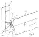
- FIG. 1 schematically shows a flap arrangement, generally designated 1, in particular for ventilation or air conditioning systems in the automotive sector, which has two flap elements 2 and 3 and a coupling device 4 connecting these two flap elements 2 and 3.
- the first flap element 2 is pivotable about a pivot axis 2 ′ indicated by the dashed line and is mounted in a known manner in a housing of the flap arrangement 1, not shown in the figures.
- the second flap element 3, which is also mounted in this housing, can be pivoted in a corresponding manner about the second pivot axis 3 ′ represented by the further dashed line.
- Such a flap arrangement with the essentially orthogonal pivot axes 2 ', 3' of the flap elements 2, 3 is known per se and therefore need not be described in detail.
- the coupling device 4 serves for a pivoting movement of the first, which is movable about the first pivot axis 2 ′ To convert flap element 2 by a defined first swivel angle into a corresponding swivel movement of second flap element 3 of flap arrangement 1, which is movable about second swivel axis 3 '.
- the coupling device 4 has a first actuating element 5, which is fixedly connected to the first flap element 2 and acts as a lever, that at its free end 5 opposite the first flap element 2 has a preferably in the direction of First pivot axis 2 'extending, preferably integrally formed with the first actuating element 5 control pin 6.
- the first actuating element 5 of the coupling device 1 interacts with a lever-like second actuating element 7, which is firmly connected to the second flap element 3 and has a control cam 8 with two guide tracks 8a and 8b at its free end 7 '(see FIGS. 2a-2c, 3a -3c) for the control pin 6, which is also preferably formed as an integral part of the second actuating element 7.
- control pin 6 in the exemplary embodiment described has an elliptical cross section, which is preferably constant over the entire longitudinal region of the control pin 6.
- control pin 6 of the first actuating element 5 only over its transmission area, that is over that longitudinal area that with a pivoting movement of the flap elements 2, 3 from their initial position into their end position with the guideways 8a and 8b of the control cam 8, is constant.
- the constant cross-section in the axial direction of the control bolt 6 advantageously has the effect that, when axially fixing it, it is no longer necessary to adhere to extremely tight tolerances in order to ensure that the coupling device 4 functions properly.
- the immersion depth of the elliptical control pin 6 of the first actuating element 5 in the control curve 8 of the second actuating element 7 no longer plays such a critical role as in the case of one previously used tapered bolts. It is also advantageous that even a force-related deformation of the control pin 6 cannot lead to a jamming of the coupling device 4 and thus to an inoperability of the flap arrangement 1.
- FIGS. 2a-2c and 3a-3c a schematically illustrated pivoting movement to the flap arrangement 1.
- Figures 2a and 3a show in a side view and in a plan view of the arrangement of Figure 1, the flap arrangement in its initial position.
- the upper part of the elliptical control pin 6 is attached to the two guide tracks 8a, 8b of the control cam 8, whereby - as can best be seen in FIG. 3a - it does not have the main apices HS1 and HS2 of the elliptical cross section on the guide surfaces 8a, 8b the control curve 8 occurs, but is laterally offset on this.
- the elliptical control pin 6 slides along the guide tracks 8a, 8b.
- the elliptical control pin 6 sets in the middle position of the pivoting movement with the main apices HS1 and HS2 of the elliptical cross-section on the guideways 8a, 8b of the control cam 8, so that the main axes of the cross-sectional ellipse are substantially orthogonal to the guideways 8a, 8b.
- the dimensioning of the elliptical cross-section of the control pin 6 and its arrangement on the first actuating element 5 of the coupling device 4 are readily obtained depending on the configuration of the design of the guide tracks 8a, 8b of the control cam 8, which defines the second swivel angle the ellipse are dimensioned such that they are - as best seen in FIG. 2b - in a central position of the pivoting movement of the flap elements 2, 3 equal to the smallest distance between the two guide surfaces 8a, 8b of the control cam 8.
Landscapes
- Engineering & Computer Science (AREA)
- Mechanical Engineering (AREA)
- Physics & Mathematics (AREA)
- Thermal Sciences (AREA)
- Chemical & Material Sciences (AREA)
- Combustion & Propulsion (AREA)
- General Engineering & Computer Science (AREA)
- Transmission Devices (AREA)
- Devices For Indicating Variable Information By Combining Individual Elements (AREA)
- Mechanical Operated Clutches (AREA)
Claims (11)
- Dispositif d'accouplement pour un ensemble de volets, qui comporte deux volets (2, 3) dont les axes de pivotement (2', 3') sont disposés sensiblement orthogonalement l'un par rapport à l'autre, ce dispositif d'accouplement (4) permettant de convertir un mouvement de pivotement du premier volet (2) en un mouvement de pivotement du second volet (3) de l'ensemble de volets (1) par le fait qu'une broche de commande (6) d'un premier élément d'actionnement (5) du dispositif d'accouplement, relié au premier volet, s'engage dans une came de commande d'un second élément d'actionnement (7) du dispositif d'accouplement qui est relié au second volet, caractérisé en ce que la broche de commande (6) du premier élément d'actionnement (5) du dispositif d'accouplement (4) comporte, au moins dans sa partie de longueur qui est en prise avec la came de commande (8) du second élément d'actionnement (7) pendant le mouvement de pivotement, une section sensiblement elliptique et constante sur cette partie de longueur.
- Dispositif d'accouplement pour ensemble de volets selon la revendication 1, caractérisé en ce que l'axe principal de la section elliptique de la broche de commande (6) a une dimension égale au demi-espacement minimal entre deux surfaces de guidage (8a, 8b) mutuellement opposées de la came de commande (8) du second élément d'actionnement (7) du dispositif d'accouplement (4).
- Dispositif d'accouplement pour ensemble de volets selon la revendication 1 ou 2, caractérisé en ce que, dans une position médiane du mouvement de pivotement du second volet (3), l'axe principal de la section elliptique de la broche de commande (6) du premier élément d'actionnement (5) du dispositif d'accouplement (4) est orienté perpendiculairement aux voies de guidage (8a, 8b) de la came de commande (8) du second élément d'actionnement (7).
- Dispositif d'accouplement pour ensemble de volets selon la revendication 3, caractérisé en ce que, dans la position médiane du mouvement de pivotement du second volet (3), la section elliptique de la broche de commande (6) est en prise dans l'essentiel, seulement par ses sommets principaux (HS1, HS2) avec les voies de guidage (8a, 8b) de la came de commande (8) du second élément d'actionnement (7) du dispositif d'accouplement (4).
- Dispositif d'accouplement pour ensemble de volets selon la revendication 1 ou 2, caractérisé en ce que les axes secondaires de la section elliptique de la broche de commande (6) sont définis de telle sorte, que, dans la position initiale et dans la position finale des volets (2, 3) de l'ensemble de volets (1), la broche de commande (6) du premier élément d'actionnement (5) soit en prise avec les voies de guidage (8a, 8b) de la came de commande (8) du second élément d'actionnement (7) du dispositif d'accouplement (4).
- Dispositif d'accouplement pour ensemble de volets selon la revendication 1, caractérisé en ce que la broche de commande (6) fait partie intégrante du premier élément d'actionnement (5).
- Dispositif d'accouplement pour ensemble de volets selon la revendication 1, caractérisé en ce que la came de commande (8) fait partie intégrante du second élément d'actionnement (7) du dispositif d'accouplement (4).
- Dispositif d'accouplement pour ensemble de volets selon la revendication 1, caractérisé en ce que le premier élément d' actionnement (5), agencé en forme de levier, du dispositif d'accouplement (4), est relié solidement au premier volet (2) de l'ensemble de volets (1).
- Dispositif d'accouplement pour ensemble de volets selon la revendication 1, caractérisé en ce que le second élément d'actionnement (7), agencé en forme de levier, du dispositif d'accouplement (4) est relié solidement au second volet (3) de l'ensemble de volets (1).
- Ensemble de volets comportant deux volets (2, 3) disposés sensiblement perpendiculairement entre eux, caractérisé par l'utilisation d'un dispositif d'accouplement (4) selon au moins une des revendications 1 à 9.
- Ensemble de volets, selon la revendication 10, caractérisé par son utilisation dans une installation de ventilation ou de climatisation, notamment d'une automobile.
Applications Claiming Priority (2)
| Application Number | Priority Date | Filing Date | Title |
|---|---|---|---|
| DE4334862 | 1993-10-13 | ||
| DE4334862A DE4334862A1 (de) | 1993-10-13 | 1993-10-13 | Kopplungseinrichtung für eine Klappenanordnung |
Publications (2)
| Publication Number | Publication Date |
|---|---|
| EP0648626A1 EP0648626A1 (fr) | 1995-04-19 |
| EP0648626B1 true EP0648626B1 (fr) | 1997-03-12 |
Family
ID=6500031
Family Applications (1)
| Application Number | Title | Priority Date | Filing Date |
|---|---|---|---|
| EP94114193A Expired - Lifetime EP0648626B1 (fr) | 1993-10-13 | 1994-09-09 | Dispositif de couplage pour un agencement des ailettes |
Country Status (3)
| Country | Link |
|---|---|
| EP (1) | EP0648626B1 (fr) |
| DE (2) | DE4334862A1 (fr) |
| ES (1) | ES2098839T3 (fr) |
Families Citing this family (1)
| Publication number | Priority date | Publication date | Assignee | Title |
|---|---|---|---|---|
| DE60306749T2 (de) * | 2003-04-18 | 2007-07-12 | Denso Thermal Systems S.P.A., Poirino | Verteiler für Belüftungsluft für Fahrzeuge |
Family Cites Families (7)
| Publication number | Priority date | Publication date | Assignee | Title |
|---|---|---|---|---|
| JPS60203522A (ja) * | 1984-03-29 | 1985-10-15 | Nissan Motor Co Ltd | ベンチレ−タ−のル−バ−取付構造 |
| JPS62173209U (fr) * | 1986-04-25 | 1987-11-04 | ||
| US4796518A (en) * | 1987-12-07 | 1989-01-10 | General Motors Corporation | Articulated air vane arrangement |
| JP2512982B2 (ja) * | 1988-02-09 | 1996-07-03 | 日本電装株式会社 | 連動機構 |
| DE3910489A1 (de) * | 1989-03-31 | 1990-10-04 | Siemens Ag | Verfahren zur frischluftsteuerung in der mittelebene eines kraftfahrzeuges und einrichtung zur durchfuehrung des verfahrens |
| DE4012215C1 (fr) * | 1990-04-14 | 1991-11-14 | Mercedes-Benz Aktiengesellschaft, 7000 Stuttgart, De | |
| IT227450Y1 (it) * | 1992-01-17 | 1997-12-15 | Foggini Progetti | Bocchetta di aerazione per autoveicoli, con mezzi a cursore perfeziona ti per il comando delle palette di orientamento del flusso. |
-
1993
- 1993-10-13 DE DE4334862A patent/DE4334862A1/de not_active Withdrawn
-
1994
- 1994-09-09 DE DE59402036T patent/DE59402036D1/de not_active Expired - Fee Related
- 1994-09-09 EP EP94114193A patent/EP0648626B1/fr not_active Expired - Lifetime
- 1994-09-09 ES ES94114193T patent/ES2098839T3/es not_active Expired - Lifetime
Also Published As
| Publication number | Publication date |
|---|---|
| ES2098839T3 (es) | 1997-05-01 |
| DE59402036D1 (de) | 1997-04-17 |
| EP0648626A1 (fr) | 1995-04-19 |
| DE4334862A1 (de) | 1995-04-20 |
Similar Documents
| Publication | Publication Date | Title |
|---|---|---|
| EP0785877B1 (fr) | Dispositif de verrouillage pour sieges de vehicules | |
| DE102004035599B3 (de) | Beschlag für einen Fahrzeugsitz | |
| EP1590226B1 (fr) | Dispositif de serrage pour colonne de direction | |
| WO2018060173A1 (fr) | Unité à broche | |
| DE102008017019A1 (de) | Gelenkbeschlag für Kraftfahrzeugsitze und mit einer Ronde | |
| DE3829109C2 (de) | Elektrischer Schalter, insbesondere Lenkstockschalter für Kraftfahrzeuge | |
| WO1998034763A1 (fr) | Dispositif de prehension | |
| DE102020128569B4 (de) | Neigungshebelbaugruppe | |
| DE102018113895A1 (de) | System zur Befestigung einer ersten Komponente an einer zweiten Komponente | |
| DE102017212073A1 (de) | Zahnstangengetriebe für ein Kraftfahrzeug | |
| DE3008418C2 (de) | Vorrichtung zur Schraubbefestigung eines Gegenstandes an der Vorderseite eines Bleches oder dergleichen mit unzugänglicher Rückseite | |
| DE3715496A1 (de) | Zweiteiliges verbindungselement zum justierbaren verbinden zweier bauteile | |
| WO2020249165A1 (fr) | Ensemble de leviers pour des applications en technique automobile | |
| EP0786787A2 (fr) | Commutateur à poussoir autoréglable | |
| WO2014048817A1 (fr) | Dispositif de verrouillage conçu pour un composant de véhicule et siège de véhicule | |
| EP0648626B1 (fr) | Dispositif de couplage pour un agencement des ailettes | |
| DE4419411C2 (de) | Gelenkbeschlag für Fahrzeugsitze, insbesondere Kraftfahrzeugsitze | |
| DE102016123052B4 (de) | Türdrückeranordnung sowie Verfahren zur Montage einer Türdrückeranordnung | |
| DE3843030C1 (fr) | ||
| EP0128111B1 (fr) | Mécanisme de déplacement longitudinal pour sièges de véhicules ayant un dispositif de déplacement actionné par moteur et un guidage longitudinal | |
| DE19816248C1 (de) | Lehneneinstellbeschlag für einen Fahrzeugsitz | |
| EP0318720A2 (fr) | Dispositif automatique de réglage de la longueur d'un câble Bowden | |
| DE202004015779U1 (de) | Stellantrieb in einem Kraftfahrzeug | |
| EP0855486A2 (fr) | Actionneur pour un dispositif de verrouillage pour portes ou capots d'un véhicule automobile | |
| DE102016006873A1 (de) | Verriegelungseinrichtung für eine Kopfstütze einer Fahrzeugsitzanlage |
Legal Events
| Date | Code | Title | Description |
|---|---|---|---|
| PUAI | Public reference made under article 153(3) epc to a published international application that has entered the european phase |
Free format text: ORIGINAL CODE: 0009012 |
|
| 17P | Request for examination filed |
Effective date: 19950131 |
|
| AK | Designated contracting states |
Kind code of ref document: A1 Designated state(s): DE ES FR GB IT |
|
| GRAG | Despatch of communication of intention to grant |
Free format text: ORIGINAL CODE: EPIDOS AGRA |
|
| GRAH | Despatch of communication of intention to grant a patent |
Free format text: ORIGINAL CODE: EPIDOS IGRA |
|
| 17Q | First examination report despatched |
Effective date: 19960731 |
|
| ITF | It: translation for a ep patent filed |
Owner name: DE DOMINICIS & MAYER S.R.L. |
|
| GRAH | Despatch of communication of intention to grant a patent |
Free format text: ORIGINAL CODE: EPIDOS IGRA |
|
| GRAA | (expected) grant |
Free format text: ORIGINAL CODE: 0009210 |
|
| AK | Designated contracting states |
Kind code of ref document: B1 Designated state(s): DE ES FR GB IT |
|
| GBT | Gb: translation of ep patent filed (gb section 77(6)(a)/1977) |
Effective date: 19970321 |
|
| REF | Corresponds to: |
Ref document number: 59402036 Country of ref document: DE Date of ref document: 19970417 |
|
| REG | Reference to a national code |
Ref country code: ES Ref legal event code: FG2A Ref document number: 2098839 Country of ref document: ES Kind code of ref document: T3 |
|
| ET | Fr: translation filed | ||
| PLBE | No opposition filed within time limit |
Free format text: ORIGINAL CODE: 0009261 |
|
| STAA | Information on the status of an ep patent application or granted ep patent |
Free format text: STATUS: NO OPPOSITION FILED WITHIN TIME LIMIT |
|
| 26N | No opposition filed | ||
| PGFP | Annual fee paid to national office [announced via postgrant information from national office to epo] |
Ref country code: GB Payment date: 19980828 Year of fee payment: 5 |
|
| PGFP | Annual fee paid to national office [announced via postgrant information from national office to epo] |
Ref country code: ES Payment date: 19980918 Year of fee payment: 5 |
|
| PG25 | Lapsed in a contracting state [announced via postgrant information from national office to epo] |
Ref country code: GB Free format text: LAPSE BECAUSE OF NON-PAYMENT OF DUE FEES Effective date: 19990909 |
|
| PG25 | Lapsed in a contracting state [announced via postgrant information from national office to epo] |
Ref country code: ES Free format text: LAPSE BECAUSE OF NON-PAYMENT OF DUE FEES Effective date: 19990910 |
|
| GBPC | Gb: european patent ceased through non-payment of renewal fee |
Effective date: 19990909 |
|
| REG | Reference to a national code |
Ref country code: ES Ref legal event code: FD2A Effective date: 20001013 |
|
| PG25 | Lapsed in a contracting state [announced via postgrant information from national office to epo] |
Ref country code: IT Free format text: LAPSE BECAUSE OF NON-PAYMENT OF DUE FEES;WARNING: LAPSES OF ITALIAN PATENTS WITH EFFECTIVE DATE BEFORE 2007 MAY HAVE OCCURRED AT ANY TIME BEFORE 2007. THE CORRECT EFFECTIVE DATE MAY BE DIFFERENT FROM THE ONE RECORDED. Effective date: 20050909 |
|
| PGFP | Annual fee paid to national office [announced via postgrant information from national office to epo] |
Ref country code: FR Payment date: 20050921 Year of fee payment: 12 |
|
| PGFP | Annual fee paid to national office [announced via postgrant information from national office to epo] |
Ref country code: DE Payment date: 20051005 Year of fee payment: 12 |
|
| PG25 | Lapsed in a contracting state [announced via postgrant information from national office to epo] |
Ref country code: DE Free format text: LAPSE BECAUSE OF NON-PAYMENT OF DUE FEES Effective date: 20070403 |
|
| REG | Reference to a national code |
Ref country code: FR Ref legal event code: ST Effective date: 20070531 |
|
| PG25 | Lapsed in a contracting state [announced via postgrant information from national office to epo] |
Ref country code: FR Free format text: LAPSE BECAUSE OF NON-PAYMENT OF DUE FEES Effective date: 20061002 |