EP0648626B1 - Coupling device for vane arrangement - Google Patents
Coupling device for vane arrangement Download PDFInfo
- Publication number
- EP0648626B1 EP0648626B1 EP94114193A EP94114193A EP0648626B1 EP 0648626 B1 EP0648626 B1 EP 0648626B1 EP 94114193 A EP94114193 A EP 94114193A EP 94114193 A EP94114193 A EP 94114193A EP 0648626 B1 EP0648626 B1 EP 0648626B1
- Authority
- EP
- European Patent Office
- Prior art keywords
- coupling device
- flap
- actuating element
- accordance
- control
- Prior art date
- Legal status (The legal status is an assumption and is not a legal conclusion. Google has not performed a legal analysis and makes no representation as to the accuracy of the status listed.)
- Expired - Lifetime
Links
Images


Classifications
-
- F—MECHANICAL ENGINEERING; LIGHTING; HEATING; WEAPONS; BLASTING
- F24—HEATING; RANGES; VENTILATING
- F24F—AIR-CONDITIONING; AIR-HUMIDIFICATION; VENTILATION; USE OF AIR CURRENTS FOR SCREENING
- F24F13/00—Details common to, or for air-conditioning, air-humidification, ventilation or use of air currents for screening
- F24F13/08—Air-flow control members, e.g. louvres, grilles, flaps or guide plates
- F24F13/10—Air-flow control members, e.g. louvres, grilles, flaps or guide plates movable, e.g. dampers
- F24F13/14—Air-flow control members, e.g. louvres, grilles, flaps or guide plates movable, e.g. dampers built up of tilting members, e.g. louvre
- F24F13/1426—Air-flow control members, e.g. louvres, grilles, flaps or guide plates movable, e.g. dampers built up of tilting members, e.g. louvre characterised by actuating means
-
- B—PERFORMING OPERATIONS; TRANSPORTING
- B60—VEHICLES IN GENERAL
- B60H—ARRANGEMENTS OF HEATING, COOLING, VENTILATING OR OTHER AIR-TREATING DEVICES SPECIALLY ADAPTED FOR PASSENGER OR GOODS SPACES OF VEHICLES
- B60H1/00—Heating, cooling or ventilating [HVAC] devices
- B60H1/00642—Control systems or circuits; Control members or indication devices for heating, cooling or ventilating devices
- B60H1/00664—Construction or arrangement of damper doors
- B60H1/00671—Damper doors moved by rotation; Grilles
-
- F—MECHANICAL ENGINEERING; LIGHTING; HEATING; WEAPONS; BLASTING
- F24—HEATING; RANGES; VENTILATING
- F24F—AIR-CONDITIONING; AIR-HUMIDIFICATION; VENTILATION; USE OF AIR CURRENTS FOR SCREENING
- F24F13/00—Details common to, or for air-conditioning, air-humidification, ventilation or use of air currents for screening
- F24F13/08—Air-flow control members, e.g. louvres, grilles, flaps or guide plates
- F24F13/10—Air-flow control members, e.g. louvres, grilles, flaps or guide plates movable, e.g. dampers
- F24F13/14—Air-flow control members, e.g. louvres, grilles, flaps or guide plates movable, e.g. dampers built up of tilting members, e.g. louvre
- F24F13/1426—Air-flow control members, e.g. louvres, grilles, flaps or guide plates movable, e.g. dampers built up of tilting members, e.g. louvre characterised by actuating means
- F24F2013/1473—Air-flow control members, e.g. louvres, grilles, flaps or guide plates movable, e.g. dampers built up of tilting members, e.g. louvre characterised by actuating means with cams or levers
Definitions
- the invention relates to a coupling device for a flap arrangement, which has two flap elements, the pivot axes of which are arranged essentially orthogonally to one another, wherein the pivoting movement of the first flap element can be converted into a swiveling movement of the second flap element of the flap arrangement by the control device, in that a control pin engages one with the first Flap element connected first actuating element of the coupling device engages in a control curve of a second actuating element of the coupling device connected to the second flap element.
- Such a coupling device is known. It is provided here that the control pin of the first actuating element engaging in the control cam of the second actuating element arranged on the second flap element is conical in order to obtain a coupling of the two flap elements that is as free of play as possible.
- this design principle has the disadvantage that an axially very tightly tolerated and axially very torsionally rigid design of the control pin of the coupling device is required in order to prevent the conical pin from becoming jammed by immersing it too deep in the control curve of the second actuating element of the coupling device.
- Such a necessary design of the control pin of the first actuating element of the coupling device and the corresponding control curve of the second actuating element disadvantageously entails a high manufacturing outlay due to the tolerance to be observed, which disadvantageously results in increased production costs.
- control pin of the first actuating element has an essentially elliptical and at least constant cross-section over its longitudinal region which engages with the control curve of the second actuating element during the pivoting movement.
- control pin of the first actuating element with an elliptical cross section constant in the axial direction is advantageous Way achieved that an exact axial fixation of the same, which is difficult to implement, is no longer necessary.
- This has the advantage that a rough tolerance of the axial mounting of the flap elements or the actuating elements of the coupling device and a force-related deformation of the control bolt according to the invention of the coupling device according to the invention cannot lead to a jamming of the flap arrangement in a particularly advantageous manner.
- the constant cross-section in the transmission area of the bolt has the effect that in a flap arrangement equipped with the coupling device according to the invention it is now completely irrelevant in an advantageous manner how far the elliptical bolt of the first actuating element plunges into the guide curve of the second actuating element, so that the complex spatial Movement of the guide curve and control pin becomes easier to control.
- the elliptical design of the control pin of the first actuating element also advantageously counteracts an increase in the play between the control pin and the control cam, as often occurs in the known constructions in the central position of the pivoting movement of the flap elements.
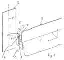
- FIG. 1 schematically shows a flap arrangement, generally designated 1, in particular for ventilation or air conditioning systems in the automotive sector, which has two flap elements 2 and 3 and a coupling device 4 connecting these two flap elements 2 and 3.
- the first flap element 2 is pivotable about a pivot axis 2 ′ indicated by the dashed line and is mounted in a known manner in a housing of the flap arrangement 1, not shown in the figures.
- the second flap element 3, which is also mounted in this housing, can be pivoted in a corresponding manner about the second pivot axis 3 ′ represented by the further dashed line.
- Such a flap arrangement with the essentially orthogonal pivot axes 2 ', 3' of the flap elements 2, 3 is known per se and therefore need not be described in detail.
- the coupling device 4 serves for a pivoting movement of the first, which is movable about the first pivot axis 2 ′ To convert flap element 2 by a defined first swivel angle into a corresponding swivel movement of second flap element 3 of flap arrangement 1, which is movable about second swivel axis 3 '.
- the coupling device 4 has a first actuating element 5, which is fixedly connected to the first flap element 2 and acts as a lever, that at its free end 5 opposite the first flap element 2 has a preferably in the direction of First pivot axis 2 'extending, preferably integrally formed with the first actuating element 5 control pin 6.
- the first actuating element 5 of the coupling device 1 interacts with a lever-like second actuating element 7, which is firmly connected to the second flap element 3 and has a control cam 8 with two guide tracks 8a and 8b at its free end 7 '(see FIGS. 2a-2c, 3a -3c) for the control pin 6, which is also preferably formed as an integral part of the second actuating element 7.
- control pin 6 in the exemplary embodiment described has an elliptical cross section, which is preferably constant over the entire longitudinal region of the control pin 6.
- control pin 6 of the first actuating element 5 only over its transmission area, that is over that longitudinal area that with a pivoting movement of the flap elements 2, 3 from their initial position into their end position with the guideways 8a and 8b of the control cam 8, is constant.
- the constant cross-section in the axial direction of the control bolt 6 advantageously has the effect that, when axially fixing it, it is no longer necessary to adhere to extremely tight tolerances in order to ensure that the coupling device 4 functions properly.
- the immersion depth of the elliptical control pin 6 of the first actuating element 5 in the control curve 8 of the second actuating element 7 no longer plays such a critical role as in the case of one previously used tapered bolts. It is also advantageous that even a force-related deformation of the control pin 6 cannot lead to a jamming of the coupling device 4 and thus to an inoperability of the flap arrangement 1.
- FIGS. 2a-2c and 3a-3c a schematically illustrated pivoting movement to the flap arrangement 1.
- Figures 2a and 3a show in a side view and in a plan view of the arrangement of Figure 1, the flap arrangement in its initial position.
- the upper part of the elliptical control pin 6 is attached to the two guide tracks 8a, 8b of the control cam 8, whereby - as can best be seen in FIG. 3a - it does not have the main apices HS1 and HS2 of the elliptical cross section on the guide surfaces 8a, 8b the control curve 8 occurs, but is laterally offset on this.
- the elliptical control pin 6 slides along the guide tracks 8a, 8b.
- the elliptical control pin 6 sets in the middle position of the pivoting movement with the main apices HS1 and HS2 of the elliptical cross-section on the guideways 8a, 8b of the control cam 8, so that the main axes of the cross-sectional ellipse are substantially orthogonal to the guideways 8a, 8b.
- the dimensioning of the elliptical cross-section of the control pin 6 and its arrangement on the first actuating element 5 of the coupling device 4 are readily obtained depending on the configuration of the design of the guide tracks 8a, 8b of the control cam 8, which defines the second swivel angle the ellipse are dimensioned such that they are - as best seen in FIG. 2b - in a central position of the pivoting movement of the flap elements 2, 3 equal to the smallest distance between the two guide surfaces 8a, 8b of the control cam 8.
Description
Die Erfindung betrifft eine Kopplungseinrichtung für eine Klappenordnung, die zwei Klappenelemente aufweist, deren Schwenkachsen im wesentlichen orthogonal zueinander angeordnet sind, wobei durch die Kopplungseinrichtung eine Schwenkbewegung des ersten Klappenelements in eine Schwenkbewegung des zweiten Klappenelements der Klappenanordnung umsetzbar ist, indem ein Steuerbolzen eines mit dem ersten Klappenelement verbundenen ersten Betätigungselements der Kopplungseinrichtung in eine Steuerkurve eines mit dem zweiten Klappenelement verbundenen zweiten Betätigungselements der Kopplungseinrichtung eingreift.The invention relates to a coupling device for a flap arrangement, which has two flap elements, the pivot axes of which are arranged essentially orthogonally to one another, wherein the pivoting movement of the first flap element can be converted into a swiveling movement of the second flap element of the flap arrangement by the control device, in that a control pin engages one with the first Flap element connected first actuating element of the coupling device engages in a control curve of a second actuating element of the coupling device connected to the second flap element.
Eine derartige Kopplungseinrichtung ist bekannt. Hierbei ist vorgesehen, daß der in der am zweiten Klappenelement angeordneten Steuerkurve des zweiten Betätigungselements eingreifende Steuerbolzen des ersten Betätigungselements konisch ausgeführt ist, um eine möglichst spielfreie Koppelung der beiden Klappenelemente zu erhalten. Dieses Ausführungsprinzip besitzt jedoch den Nachteil, daß hierbei eine axial sehr eng tolerierte und in Achsrichtung sehr verwindungssteife Auslegung des Steuerbolzens der Kopplungseinrichtung erforderlich ist, um ein Verklemmen des konischen Bolzens durch ein zu tiefes Eintauchen in die Steuerkurve des zweiten Betätigungselements der Kopplungseinrichtung zu verhindern. Eine derartige erforderliche Ausbildung des Steuerbolzens des ersten Betätigungselements der Kopplungseinrichtung sowie der korrespondierenden Steuerkurve des zweiten Betätigungselements bringt in nachteiliger Art und Weise aufgrund der dabei einzuhaltenden Toleranz einen hohen fertigungstechnischen Aufwand mit sich, welcher sich nachteiligerweise in erhöhten Produktionskosten niederschlägt.Such a coupling device is known. It is provided here that the control pin of the first actuating element engaging in the control cam of the second actuating element arranged on the second flap element is conical in order to obtain a coupling of the two flap elements that is as free of play as possible. However, this design principle has the disadvantage that an axially very tightly tolerated and axially very torsionally rigid design of the control pin of the coupling device is required in order to prevent the conical pin from becoming jammed by immersing it too deep in the control curve of the second actuating element of the coupling device. Such a necessary design of the control pin of the first actuating element of the coupling device and the corresponding control curve of the second actuating element disadvantageously entails a high manufacturing outlay due to the tolerance to be observed, which disadvantageously results in increased production costs.
Außerdem ist in nachteiliger Art und Weise selbst bei einer obigen Anforderung genugenden Ausbildung der Kopplungseinrichtung nicht gewährleistet, daß eine diese Kopplungseinrichtung aufweisende Klappenanordnung zufriedenstellend funktioniert. Durch die herstellungsbedingten Toleranzen der Gehäuseteile, in denen die Klappenelemente der Klappenanordnung gelagert sind, sowie durch Toleranzen der Klappenelemente selbst kann eine nachteilige Verschiebung des konischen Steuerbolzens des ersten Betätigungselements in axialer Richtung auftreten, die entweder in einem zu großen Spiel oder sogar in einem Verklemmen des konischen Steuerbolzens in seiner zugeordneten Steuerkurve resultieren kann. In nachteiliger Art und Weise kann dies zu einer Verminderung der Funktionsfähigkeit der Klappenanordnung oder - insbesondere im letztgenannten Fall - zu einem Blockieren der Klappenelemente der Klappenanordnung führen.In addition, it is disadvantageously not guaranteed, even with a design of the coupling device that satisfies the above requirement, that a flap arrangement having this coupling device functions satisfactorily. Due to the manufacturing tolerances of the housing parts in which the flap elements of the flap arrangement are mounted, as well as tolerances of the flap elements themselves, an adverse displacement of the conical control pin of the first actuating element in the axial direction can occur, which can either result in too much play or even in a jamming of the conical control pin in its associated control curve. In a disadvantageous manner, this can lead to a reduction in the functionality of the flap arrangement or - in particular in the latter case - to a blocking of the flap elements of the flap arrangement.
Es ist daher Aufgabe der Erfindung, eine Kopplungseinrichtung der eingangs genannten Art derart weiterzubilden, daß in besonders einfacher Art und Weise ein möglichst spielfreier Eingriff des Bolzens in seiner zugeordneten Führungsbahn gewährleistet ist.It is therefore an object of the invention to develop a coupling device of the type mentioned at the outset in such a way that, in a particularly simple manner, an engagement of the bolt in its associated guideway that is as free of play as possible is ensured.
Die Aufgabe wird erfindungsgemäß dadurch gelöst, daß der Steuerbolzen des ersten Betätigungselement wenigstens über seinen während der Schwenkbewegung mit der Steuerkurve des zweiten Betätigungselements in Eingriff stehenden Längsbereich einen im wesentlichen elliptischen und über diesen Längsbereich konstanten Querschnitt aufweist.The object is achieved in that the control pin of the first actuating element has an essentially elliptical and at least constant cross-section over its longitudinal region which engages with the control curve of the second actuating element during the pivoting movement.
Durch die erfindungsgemäße Ausbildung des Steuerbolzen des ersten Betätigungselements mit einem in Achsrichtung konstanten, elliptischen Querschnitt wird in vorteilhafter Art und Weise erreicht, daß eine nur aufwendig zu realisierende exakte Axialfixierung desselben nicht mehr notwendig ist. Dies besitzt den Vorteil, daß eine grobe Tolerierung der Axiallagerung der Klappenelemente bzw. der Betätigungselemente der Kopplungseinrichtung sowie eine kraftbedingte Verformung des erfindungsgemäßen Steuerbolzens der erfindungsgemäßen Kopplungseinrichtung in besonders vorteilhafter Art und Weise nicht zu einem Verklemmen der Klappenanordnung führen kann. Der im Übertragungsbereich des Bolzens konstante Querschnitt bewirkt, daß es bei einer mit der erfindungsgemäßen Kopplungseinrichtung ausgestatteten Klappenanordnung nunmehr in vorteilhafter Art und Weise vollkommen unerheblich ist, wie weit der elliptische Bolzen des ersten Betätigungselements in die Führungskurve des zweiten Betätigungselements eintaucht, so daß die komplexe räumliche Bewegung von Führungskurve und Steuerbolzen leichter beherrschbar wird. Durch die elliptische Ausführung des Steuerbolzen des ersten Betätigungselements wird außerdem in vorteilhafter Art und Weise einer Vergrößerung des Spiels zwischen dem Steuerbolzen und der Steuerkurve - wie sie bei den bekannten Konstruktionen in der Mittelstellung der Schwenkbewegung der Klappenelemente oft auftritt - entgegengewirkt.The inventive design of the control pin of the first actuating element with an elliptical cross section constant in the axial direction is advantageous Way achieved that an exact axial fixation of the same, which is difficult to implement, is no longer necessary. This has the advantage that a rough tolerance of the axial mounting of the flap elements or the actuating elements of the coupling device and a force-related deformation of the control bolt according to the invention of the coupling device according to the invention cannot lead to a jamming of the flap arrangement in a particularly advantageous manner. The constant cross-section in the transmission area of the bolt has the effect that in a flap arrangement equipped with the coupling device according to the invention it is now completely irrelevant in an advantageous manner how far the elliptical bolt of the first actuating element plunges into the guide curve of the second actuating element, so that the complex spatial Movement of the guide curve and control pin becomes easier to control. The elliptical design of the control pin of the first actuating element also advantageously counteracts an increase in the play between the control pin and the control cam, as often occurs in the known constructions in the central position of the pivoting movement of the flap elements.
Vorteilhafte Weiterbildungen der Erfindung ergeben sich aus den Unteransprüchen.Advantageous developments of the invention result from the subclaims.
Weitere Einzelheiten der Erfindung sind dem Ausführungsbeispiel zu entnehmen, das im folgenden anhand der Figuren beschrieben wird. Es zeigen:
- Figur 1
- ein Ausführungsbeispiel einer Klappenanordnung;
- Figuren 2a-2c und Figuren 3a-3c
- eine schematische Darstellung des Schwenkvorgangs der Klappenanordnung.
- Figure 1
- an embodiment of a flap arrangement;
- Figures 2a-2c and Figures 3a-3c
- a schematic representation of the pivoting process of the flap arrangement.
In Figur 1 ist schematisch eine allgemein mit 1 bezeichnete Klappenanordnung, insbesondere für Belüftungs- oder Klimaanlagen im Automobilbereich, dargestellt, welche zwei Klappenelemente 2 und 3 und eine diese beiden Klappenelemente 2 und 3 verbindende Kopplungseinrichtung 4 aufweist. Das erste Klappenelement 2 ist um eine durch die strichlierte Linie angedeutete Schwenkachse 2' schwenkbar und in bekannter Art und Weise in einem in den Figuren nicht dargestellten Gehäuse der Klappenanordnung 1 gelagert. Das ebenfalls in diesem Gehäuse gelagerte zweite Klappenelement 3 ist in entsprechender Art und Weise um die durch die weitere strichlierte Linie repräsentierte zweite Schwenkachse 3' schwenkbar. Eine derartige Klappenanordnung mit den im wesentlichen orthogonal zueinander verlaufenden Schwenkachsen 2', 3' der Klappenelemente 2, 3 ist an und für sich bekannt und muß daher nicht näher beschrieben werden.1 schematically shows a flap arrangement, generally designated 1, in particular for ventilation or air conditioning systems in the automotive sector, which has two
Die Kopplungseinrichtung 4 dient dazu, eine Schwenkbewegung des um die erste Schwenkachse 2' beweglichen ersten Klappenelements 2 um einen definierten ersten Schwenkwinkel in eine entsprechende Schwenkbewegung des um die zweite Schwenkachse 3' beweglichen zweiten Klappenelements 3 der Klappenanordnung 1 umzusetzen. Hierzu ist in an und für sich bekannte Art und Weise vorgesehen, daß die Kopplungseinrichtung 4 ein fest mit dem ersten Klappenelement 2 verbundenes, als Hebel fungierendes erstes Betätigungselement 5 aufweist, daß an seinem dem ersten Klappenelement 2 gegenüberliegenden freien Ende 5 einen vorzugsweise in Richtung der ersten Schwenkachse 2' verlaufenden, vorzugsweise integral mit dem ersten Betätigungselement 5 ausgebildeten Steuerbolzen 6 aufweist. Das erste Betätigungselement 5 der Kopplungseinrichtung 1 wirkt mit einem fest mit dem zweiten Klappenelement 3 verbundenen, hebelartigen zweiten Betätigungselement 7 zusammen, das an seinem freien Ende 7' eine Steuerkurve 8 mit zwei Führungsbahnen 8a und 8b (s. Fig. 2a-2c, 3a-3c) für den Steuerbolzen 6 aufweist, welche ebenfalls vorzugsweise als integraler Bestandteil des zweiten Betätigungselements 7 ausgebildet ist.The
Wichtig ist nun, daß bei dem beschriebenen Ausführungsbeispiel der Steuerbolzen 6 einen elliptischen Querschnitt aufweist, welcher vorzugsweise über den gesamten Längsbereich des Steuerbolzens 6 konstant ist. Es ist aber durchaus ausreichend, daß der Steuerbolzen 6 des ersten Betätigungselements 5 lediglich über seinen Übertragungsbereich, also über denjenigen Längsbereich, der bei einer Schwenkbewegung der Klappenelemente 2, 3 von ihrer Anfangslage in ihre Endlage mit den Führungsbahnen 8a und 8b der Steuerkurve 8 in Eingriff tritt, konstant ist. Der in Achsrichtung des Steuerbolzens 6 konstante Querschnitt bewirkt vorteilhafterweise, daß bei der Axialfixierung desselben es nicht mehr notwendig ist, äußerst enge Toleranzen einzuhalten, um eine einwandfreie Funktion der Kopplungseinrichtung 4 gewährleisten. Bei dem beschriebenen Steuerbolzen 6 mit seinem zumindest über den Übertragungsbereich konstanten, elliptischen Querschnitt spielt in vorteilhafter Art und Weise die Eintauchtiefe des elliptischen Steuerbolzens 6 des ersten Betätigungselements 5 in die Steuerkurve 8 des zweiten Betätigungselements 7 nun nicht mehr eine derart kritische Rolle wie bei einem bisher verwendeten konisch geformten Bolzen. Außerdem ist von Vorteil, daß auch eine kraftbedingte Verformung des Steuerbolzens 6 nicht zu einer Verklemmung der Kopplungseinrichtung 4 und somit zu einer Funktionsunfähigkeit der Klappenanordnung 1 führen kann.It is important that the
Es ist zwar grundsätzlich auch denkbar, den elliptischen Steuerbolzen 6 in zylindrischer Form auszuführen. Diese Ausgestaltung besitzt jedoch den Nachteil, daß in der Mittelstellung der Schwenkbewegung der Klappenelemente 2 und 3 von ihrer Ausgangs- in ihre Endstellung ein unerwünschtes Spiel zwischen dem Steuerbolzen 6 und den Führungsbahnen 8a, 8b der Steuerkurve 8 des zweiten Betätigungselements 7 der Kopplungseinrichtung 4 auftritt. Dies wird durch die elliptische Ausgestaltung des Bolzens 6 vermieden, durch die gewährleistet ist, daß der Steuerbolzen 6 des ersten Betätigungselements 5 stets in entsprechendem Wirkeingriff mit den Führungsbahnen 8a, 8b der Steuerkurve 8 steht.In principle, it is also conceivable to design the
Die Funktionsweise der beschriebenen Kopplungseinrichtung 4 wird nun anhand der Figuren 2a-2c und 3a-3c schematisch dargestellten Schwenkbewegung zur Klappenanordnung 1 erläutert. Die Figuren 2a und 3a zeigen in einer Seitenansicht bzw. in einer Draufsicht auf die Anordnung der Figur 1 die Klappenanordnung in ihrer Anfangsstellung. Der elliptische Steuerbolzen 6 setzt hierbei in seinem oberen Bereich an den beiden Führungsbahnen 8a, 8b der Steuerkurve 8 an, wobei er - wie am besten aus Figur 3a ersichtlich ist - nicht mit den Hauptscheiteln HS1 und HS2 des elliptischen Querschnitts an den Führungsflächen 8a, 8b der Steuerkurve 8 auftritt, sondern setzt seitlich versetzt auf diese auf.The operation of the
Wird nun das erste Klappenelement 2 aus seiner Anfangsstellung in die in den Figuren 1, 2b und 3b dargestellte Mittelstellung und dadurch das zweite Klappenelement aus seiner Anfangsstellung in die Mittelstellung seiner Schwenkbewegung bewegt, so gleitet der elliptische Steuerbolzen 6 entlang der Führungsbahnen 8a, 8b. Wie am besten aus Figur 3b ersichtlich ist, setzt der elliptische Steuerbolzen 6 in der Mittelstellung der Schwenkbewegung mit den Hauptscheiteln HS1 und HS2 des elliptischen Querschnitts an den Führungsbahnen 8a, 8b der Steuerkurve 8 an, so daß die Hauptachsen der Querschnitts-Ellipse im wesentlichen orthogonal zu den Führungsbahnen 8a, 8b verlaufen.If the
Durch eine weitere Verschwenkung des ersten Klappenelements 2 gelangen die beiden Klappenelemente 2, 3 der Klappenanordnung 1 in die in den Figuren 2c und 3c dargestellte Endstellung. In dieser setzt der Steuerbolzen 6 wiederum in seitlich neben den Hauptscheiteln HS1 und HS2 liegenden Bereichen an den Führungsbahnen 8a, 8b der Steuerkurve 8 des zweiten Betätigungselements 7 der Kopplungseinrichtung 4 an.By further pivoting the
Aus dem beschriebenden Funktionsablauf ergibt sich nun ohne weiteres die Dimensionierung des elliptischen Querschnitts des Steuerbolzens 6 sowie seine Anordnung auf dem ersten Betätigungselement 5 der Kopplungseinrichtung 4 in Abhängigkeit von der Ausgestaltung der den zweiten Schwenkwinkel festlegenden Ausbildung der Führungsbahnen 8a, 8b der Steuerkurve 8. Die Hauptachsen der Ellipse sind dabei derart bemessen, daß sie in Summe - wie am besten aus Figur 2b ersichtlich ist - in einer Mittelstellung der Schwenkbewegung der Klappenelemente 2, 3 gleich dem kleinsten Abstand zwischen den beiden Führungsflächen 8a, 8b der Steuerkurve 8 sind. Die Dimensionierung der Nebenachsen des Ellipsenquerschnitts des Steuerbolzens 6 sowie seine Anordnung auf dem ersten Betätigungselement 5 der Kopplungseinrichtung 4 ergibt sich dann aus den Erfordernissen, daß in der Anfangs- und in der Endstellung die Klappenelemente 2, 3 die Querschnitts-Ellipse des Steuerbolzens 6 an den Führungsflächen 8a, 8b der Steuerkurve 8 anliegt.From the functional sequence described, the dimensioning of the elliptical cross-section of the
Claims (11)
- A coupling device for a flap arrangement which has two flap elements (2, 3) whose axes of rotation (2', 3') are positioned essentially orthogonally to one other, whereby a rotating movement of the first flap element (2) can be converted into a rotating movement of the second flap element (3) of the flap arrangement (1) by the coupling device (4) by means of the engagement of a controlling pin (6) on a first actuating element (5) of the coupling device (4) connected to the first flap element (2) in a control curve (8) on a second actuating element (7) of the coupling device (4) connected to the second flap element (3), characterised in that at least the longitudinal section of the control pin (6) on the first actuating element (5) of the coupling device (4) which engages with the control curve (8) on the second actuating element (7) during the rotating movement has an essentially elliptical cross section which is constant over this longitudinal section.
- A coupling device for the flap arrangement in accordance with Claim 1, characterised in that the principal axis of the elliptical cross section of the control pin (6) is equal to half of the minimum distance between two opposite guide surfaces (8a, 8b) on the control curve (8) on the second actuating element (7) of the coupling device (4).
- A coupling device in accordance with Claim 1 or 2, characterised in that in the middle of the rotating movement of the second flap element (3), the principal axis of the elliptical cross section of the control pin (6) on the first actuating element (5) of the coupling device (4) is positioned orthogonally to the guide tracks (8a, 8b) of the control curve (8) on the second actuating element (7).
- A coupling device in accordance with Claim 3, characterised in that in the middle of the rotating movement of the second flap element (3), essentially only the principal apexes (HS1, HS2) of the elliptical cross section of the control pin (6) engage with the guide tracks (8a, 8b) on the control curve (8) on the second actuating element (7) of the coupling device (4).
- A coupling device in accordance with Claim 1 or 2, characterised in that the secondary axes of the elliptical cross section of the control pin (6) are determined in such a way that in the initial and final positions of the flap elements (2, 3) of the flap arrangement (1), the control pin (6) on the first actuating element (5) engages with the guide tracks (8a, 8b) on the control curve (8) on the second actuating element (7) of the coupling device (4).
- A coupling device in accordance with Claim 1, characterised in that the control pin (6) forms an integral part of the first actuating element (5).
- A coupling device in accordance with Claim 1, characterised in that the control curve (8) forms an integral part of the second actuating element (7) of the coupling device (4).
- A coupling device in accordance with Claim 1, characterised in that the lever-like first actuating element (5) of the coupling device (4) is connected rigidly to the first flap element (2) of the flap arrangement (1).
- A coupling device in accordance with Claim 1, characterised in that the lever-like second actuating element (7) of the coupling device (4) is connected rigidly to the second flap element (3) of the flap arrangement (1).
- A flap arrangement with two flap element (2, 3) positioned essentially orthogonally to one another, characterised by the use of a coupling device (4) in accordance with at least one of Claims 1 to 9.
- A flap arrangement according to Claim 10, characterised by its use in a ventilation or air conditioning system, in particular in a car.
Applications Claiming Priority (2)
| Application Number | Priority Date | Filing Date | Title |
|---|---|---|---|
| DE4334862 | 1993-10-13 | ||
| DE4334862A DE4334862A1 (en) | 1993-10-13 | 1993-10-13 | Coupling device for a flap arrangement |
Publications (2)
| Publication Number | Publication Date |
|---|---|
| EP0648626A1 EP0648626A1 (en) | 1995-04-19 |
| EP0648626B1 true EP0648626B1 (en) | 1997-03-12 |
Family
ID=6500031
Family Applications (1)
| Application Number | Title | Priority Date | Filing Date |
|---|---|---|---|
| EP94114193A Expired - Lifetime EP0648626B1 (en) | 1993-10-13 | 1994-09-09 | Coupling device for vane arrangement |
Country Status (3)
| Country | Link |
|---|---|
| EP (1) | EP0648626B1 (en) |
| DE (2) | DE4334862A1 (en) |
| ES (1) | ES2098839T3 (en) |
Families Citing this family (1)
| Publication number | Priority date | Publication date | Assignee | Title |
|---|---|---|---|---|
| ES2268318T3 (en) * | 2003-04-18 | 2007-03-16 | Denso Thermal Systems S.P.A. | AIR DISTRIBUTION ASSEMBLY FOR VEHICLES. |
Family Cites Families (7)
| Publication number | Priority date | Publication date | Assignee | Title |
|---|---|---|---|---|
| JPS60203522A (en) * | 1984-03-29 | 1985-10-15 | Nissan Motor Co Ltd | Louver setting structure for ventilator |
| JPS62173209U (en) * | 1986-04-25 | 1987-11-04 | ||
| US4796518A (en) * | 1987-12-07 | 1989-01-10 | General Motors Corporation | Articulated air vane arrangement |
| JP2512982B2 (en) * | 1988-02-09 | 1996-07-03 | 日本電装株式会社 | Interlocking mechanism |
| DE3910489A1 (en) * | 1989-03-31 | 1990-10-04 | Siemens Ag | METHOD FOR FRESH AIR CONTROL IN THE MID-LEVEL OF A MOTOR VEHICLE AND DEVICE FOR IMPLEMENTING THE METHOD |
| DE4012215C1 (en) * | 1990-04-14 | 1991-11-14 | Mercedes-Benz Aktiengesellschaft, 7000 Stuttgart, De | |
| IT227450Y1 (en) * | 1992-01-17 | 1997-12-15 | Foggini Progetti | AERATION VENT FOR VEHICLES, WITH CURSOR VEHICLES, PERFECT FOR THE CONTROL OF THE FLOW ORIENTATION PALETTE. |
-
1993
- 1993-10-13 DE DE4334862A patent/DE4334862A1/en not_active Withdrawn
-
1994
- 1994-09-09 DE DE59402036T patent/DE59402036D1/en not_active Expired - Fee Related
- 1994-09-09 EP EP94114193A patent/EP0648626B1/en not_active Expired - Lifetime
- 1994-09-09 ES ES94114193T patent/ES2098839T3/en not_active Expired - Lifetime
Also Published As
| Publication number | Publication date |
|---|---|
| ES2098839T3 (en) | 1997-05-01 |
| EP0648626A1 (en) | 1995-04-19 |
| DE4334862A1 (en) | 1995-04-20 |
| DE59402036D1 (en) | 1997-04-17 |
Similar Documents
| Publication | Publication Date | Title |
|---|---|---|
| EP0785877B1 (en) | Locking device for vehicle seats | |
| DE102004035599B3 (en) | Fitting for a vehicle seat | |
| EP1590226B1 (en) | Clamping device for a steering column | |
| WO2018060173A1 (en) | Spindle unit | |
| DE102008017019A1 (en) | Articulated fitting for motor vehicle seats and with a round plate | |
| DE3829109C2 (en) | Electrical switches, in particular steering column switches for motor vehicles | |
| WO1998034763A1 (en) | Gripping device | |
| DE102020128569B4 (en) | TILT CONTROL ASSEMBLY | |
| DE102018113895A1 (en) | System for fixing a first component to a second component | |
| DE102017212073A1 (en) | Rack and pinion for a motor vehicle | |
| DE3008418C2 (en) | Device for screwing an object to the front of a sheet metal or the like with an inaccessible rear | |
| DE3715496A1 (en) | Two-part connecting element for the adjustable connection of two components | |
| WO2020249165A1 (en) | Lever assembly for automotive applications | |
| EP0786787A2 (en) | Self-adjusting tappet-switch | |
| WO2014048817A1 (en) | Locking device for a vehicle component and vehicle seat | |
| EP0648626B1 (en) | Coupling device for vane arrangement | |
| DE4419411C2 (en) | Articulated fitting for vehicle seats, in particular motor vehicle seats | |
| DE102016123052B4 (en) | Door handle arrangement and method for assembling a door handle arrangement | |
| DE3843030C1 (en) | ||
| EP0128111B1 (en) | Longitudinal adjusting arrangement for vehicle seats with a power-operated adjusting device and a longitudinal guide | |
| DE19816248C1 (en) | Lean adjuster for motor vehicle backrest | |
| EP0318720A2 (en) | Automatic length adjusting device of a Bowden cable | |
| DE202004015779U1 (en) | Actuator in a motor vehicle | |
| EP0855486A2 (en) | Central locking actuator for doors or covers on motor vehicles | |
| DE102016006873A1 (en) | Locking device for a headrest of a vehicle seat system |
Legal Events
| Date | Code | Title | Description |
|---|---|---|---|
| PUAI | Public reference made under article 153(3) epc to a published international application that has entered the european phase |
Free format text: ORIGINAL CODE: 0009012 |
|
| 17P | Request for examination filed |
Effective date: 19950131 |
|
| AK | Designated contracting states |
Kind code of ref document: A1 Designated state(s): DE ES FR GB IT |
|
| GRAG | Despatch of communication of intention to grant |
Free format text: ORIGINAL CODE: EPIDOS AGRA |
|
| GRAH | Despatch of communication of intention to grant a patent |
Free format text: ORIGINAL CODE: EPIDOS IGRA |
|
| 17Q | First examination report despatched |
Effective date: 19960731 |
|
| ITF | It: translation for a ep patent filed |
Owner name: DE DOMINICIS & MAYER S.R.L. |
|
| GRAH | Despatch of communication of intention to grant a patent |
Free format text: ORIGINAL CODE: EPIDOS IGRA |
|
| GRAA | (expected) grant |
Free format text: ORIGINAL CODE: 0009210 |
|
| AK | Designated contracting states |
Kind code of ref document: B1 Designated state(s): DE ES FR GB IT |
|
| GBT | Gb: translation of ep patent filed (gb section 77(6)(a)/1977) |
Effective date: 19970321 |
|
| REF | Corresponds to: |
Ref document number: 59402036 Country of ref document: DE Date of ref document: 19970417 |
|
| REG | Reference to a national code |
Ref country code: ES Ref legal event code: FG2A Ref document number: 2098839 Country of ref document: ES Kind code of ref document: T3 |
|
| ET | Fr: translation filed | ||
| PLBE | No opposition filed within time limit |
Free format text: ORIGINAL CODE: 0009261 |
|
| STAA | Information on the status of an ep patent application or granted ep patent |
Free format text: STATUS: NO OPPOSITION FILED WITHIN TIME LIMIT |
|
| 26N | No opposition filed | ||
| PGFP | Annual fee paid to national office [announced via postgrant information from national office to epo] |
Ref country code: GB Payment date: 19980828 Year of fee payment: 5 |
|
| PGFP | Annual fee paid to national office [announced via postgrant information from national office to epo] |
Ref country code: ES Payment date: 19980918 Year of fee payment: 5 |
|
| PG25 | Lapsed in a contracting state [announced via postgrant information from national office to epo] |
Ref country code: GB Free format text: LAPSE BECAUSE OF NON-PAYMENT OF DUE FEES Effective date: 19990909 |
|
| PG25 | Lapsed in a contracting state [announced via postgrant information from national office to epo] |
Ref country code: ES Free format text: LAPSE BECAUSE OF NON-PAYMENT OF DUE FEES Effective date: 19990910 |
|
| GBPC | Gb: european patent ceased through non-payment of renewal fee |
Effective date: 19990909 |
|
| REG | Reference to a national code |
Ref country code: ES Ref legal event code: FD2A Effective date: 20001013 |
|
| PG25 | Lapsed in a contracting state [announced via postgrant information from national office to epo] |
Ref country code: IT Free format text: LAPSE BECAUSE OF NON-PAYMENT OF DUE FEES;WARNING: LAPSES OF ITALIAN PATENTS WITH EFFECTIVE DATE BEFORE 2007 MAY HAVE OCCURRED AT ANY TIME BEFORE 2007. THE CORRECT EFFECTIVE DATE MAY BE DIFFERENT FROM THE ONE RECORDED. Effective date: 20050909 |
|
| PGFP | Annual fee paid to national office [announced via postgrant information from national office to epo] |
Ref country code: FR Payment date: 20050921 Year of fee payment: 12 |
|
| PGFP | Annual fee paid to national office [announced via postgrant information from national office to epo] |
Ref country code: DE Payment date: 20051005 Year of fee payment: 12 |
|
| PG25 | Lapsed in a contracting state [announced via postgrant information from national office to epo] |
Ref country code: DE Free format text: LAPSE BECAUSE OF NON-PAYMENT OF DUE FEES Effective date: 20070403 |
|
| REG | Reference to a national code |
Ref country code: FR Ref legal event code: ST Effective date: 20070531 |
|
| PG25 | Lapsed in a contracting state [announced via postgrant information from national office to epo] |
Ref country code: FR Free format text: LAPSE BECAUSE OF NON-PAYMENT OF DUE FEES Effective date: 20061002 |