EP0648552B1 - Convoyeur isolé mobile pour la coulée continue de brames - Google Patents
Convoyeur isolé mobile pour la coulée continue de brames Download PDFInfo
- Publication number
- EP0648552B1 EP0648552B1 EP94115946A EP94115946A EP0648552B1 EP 0648552 B1 EP0648552 B1 EP 0648552B1 EP 94115946 A EP94115946 A EP 94115946A EP 94115946 A EP94115946 A EP 94115946A EP 0648552 B1 EP0648552 B1 EP 0648552B1
- Authority
- EP
- European Patent Office
- Prior art keywords
- movable
- conveyor
- tunnel furnace
- insulated
- movable insulated
- Prior art date
- Legal status (The legal status is an assumption and is not a legal conclusion. Google has not performed a legal analysis and makes no representation as to the accuracy of the status listed.)
- Expired - Lifetime
Links
- 238000009749 continuous casting Methods 0.000 title claims abstract description 15
- 238000005096 rolling process Methods 0.000 claims abstract description 35
- 238000005266 casting Methods 0.000 claims abstract description 23
- 238000011144 upstream manufacturing Methods 0.000 claims abstract description 5
- 238000010438 heat treatment Methods 0.000 claims description 10
- 239000003517 fume Substances 0.000 claims description 7
- 230000006698 induction Effects 0.000 claims description 5
- 238000007689 inspection Methods 0.000 claims description 4
- 238000010008 shearing Methods 0.000 claims description 3
- 230000002596 correlated effect Effects 0.000 claims 1
- 238000009413 insulation Methods 0.000 description 6
- 239000000047 product Substances 0.000 description 4
- 238000012546 transfer Methods 0.000 description 4
- 230000003750 conditioning effect Effects 0.000 description 3
- 239000012809 cooling fluid Substances 0.000 description 3
- 238000012423 maintenance Methods 0.000 description 3
- 238000012545 processing Methods 0.000 description 3
- 230000002441 reversible effect Effects 0.000 description 3
- 238000001816 cooling Methods 0.000 description 2
- 239000006185 dispersion Substances 0.000 description 2
- 239000000463 material Substances 0.000 description 2
- 238000004891 communication Methods 0.000 description 1
- 230000007547 defect Effects 0.000 description 1
- 230000001419 dependent effect Effects 0.000 description 1
- 238000006073 displacement reaction Methods 0.000 description 1
- 238000011143 downstream manufacturing Methods 0.000 description 1
- 239000000446 fuel Substances 0.000 description 1
- 239000012212 insulator Substances 0.000 description 1
- 230000013011 mating Effects 0.000 description 1
- 238000000034 method Methods 0.000 description 1
- 238000012544 monitoring process Methods 0.000 description 1
- 230000001681 protective effect Effects 0.000 description 1
- 239000011265 semifinished product Substances 0.000 description 1
- 230000003019 stabilising effect Effects 0.000 description 1
Images

Classifications
-
- C—CHEMISTRY; METALLURGY
- C21—METALLURGY OF IRON
- C21D—MODIFYING THE PHYSICAL STRUCTURE OF FERROUS METALS; GENERAL DEVICES FOR HEAT TREATMENT OF FERROUS OR NON-FERROUS METALS OR ALLOYS; MAKING METAL MALLEABLE, e.g. BY DECARBURISATION OR TEMPERING
- C21D9/00—Heat treatment, e.g. annealing, hardening, quenching or tempering, adapted for particular articles; Furnaces therefor
- C21D9/0081—Heat treatment, e.g. annealing, hardening, quenching or tempering, adapted for particular articles; Furnaces therefor for slabs; for billets
-
- B—PERFORMING OPERATIONS; TRANSPORTING
- B21—MECHANICAL METAL-WORKING WITHOUT ESSENTIALLY REMOVING MATERIAL; PUNCHING METAL
- B21B—ROLLING OF METAL
- B21B1/00—Metal-rolling methods or mills for making semi-finished products of solid or profiled cross-section; Sequence of operations in milling trains; Layout of rolling-mill plant, e.g. grouping of stands; Succession of passes or of sectional pass alternations
- B21B1/46—Metal-rolling methods or mills for making semi-finished products of solid or profiled cross-section; Sequence of operations in milling trains; Layout of rolling-mill plant, e.g. grouping of stands; Succession of passes or of sectional pass alternations for rolling metal immediately subsequent to continuous casting
- B21B1/466—Metal-rolling methods or mills for making semi-finished products of solid or profiled cross-section; Sequence of operations in milling trains; Layout of rolling-mill plant, e.g. grouping of stands; Succession of passes or of sectional pass alternations for rolling metal immediately subsequent to continuous casting in a non-continuous process, i.e. the cast being cut before rolling
-
- F—MECHANICAL ENGINEERING; LIGHTING; HEATING; WEAPONS; BLASTING
- F27—FURNACES; KILNS; OVENS; RETORTS
- F27B—FURNACES, KILNS, OVENS OR RETORTS IN GENERAL; OPEN SINTERING OR LIKE APPARATUS
- F27B9/00—Furnaces through which the charge is moved mechanically, e.g. of tunnel type; Similar furnaces in which the charge moves by gravity
- F27B9/14—Furnaces through which the charge is moved mechanically, e.g. of tunnel type; Similar furnaces in which the charge moves by gravity characterised by the path of the charge during treatment; characterised by the means by which the charge is moved during treatment
- F27B9/20—Furnaces through which the charge is moved mechanically, e.g. of tunnel type; Similar furnaces in which the charge moves by gravity characterised by the path of the charge during treatment; characterised by the means by which the charge is moved during treatment the charge moving in a substantially straight path
- F27B9/24—Furnaces through which the charge is moved mechanically, e.g. of tunnel type; Similar furnaces in which the charge moves by gravity characterised by the path of the charge during treatment; characterised by the means by which the charge is moved during treatment the charge moving in a substantially straight path being carried by a conveyor
-
- B—PERFORMING OPERATIONS; TRANSPORTING
- B21—MECHANICAL METAL-WORKING WITHOUT ESSENTIALLY REMOVING MATERIAL; PUNCHING METAL
- B21B—ROLLING OF METAL
- B21B15/00—Arrangements for performing additional metal-working operations specially combined with or arranged in, or specially adapted for use in connection with, metal-rolling mills
- B21B15/0007—Cutting or shearing the product
- B21B2015/0014—Cutting or shearing the product transversely to the rolling direction
-
- B—PERFORMING OPERATIONS; TRANSPORTING
- B21—MECHANICAL METAL-WORKING WITHOUT ESSENTIALLY REMOVING MATERIAL; PUNCHING METAL
- B21B—ROLLING OF METAL
- B21B39/00—Arrangements for moving, supporting, or positioning work, or controlling its movement, combined with or arranged in, or specially adapted for use in connection with, metal-rolling mills
- B21B39/02—Feeding or supporting work; Braking or tensioning arrangements, e.g. threading arrangements
- B21B39/12—Arrangement or installation of roller tables in relation to a roll stand
-
- B—PERFORMING OPERATIONS; TRANSPORTING
- B21—MECHANICAL METAL-WORKING WITHOUT ESSENTIALLY REMOVING MATERIAL; PUNCHING METAL
- B21B—ROLLING OF METAL
- B21B45/00—Devices for surface or other treatment of work, specially combined with or arranged in, or specially adapted for use in connection with, metal-rolling mills
- B21B45/004—Heating the product
-
- Y—GENERAL TAGGING OF NEW TECHNOLOGICAL DEVELOPMENTS; GENERAL TAGGING OF CROSS-SECTIONAL TECHNOLOGIES SPANNING OVER SEVERAL SECTIONS OF THE IPC; TECHNICAL SUBJECTS COVERED BY FORMER USPC CROSS-REFERENCE ART COLLECTIONS [XRACs] AND DIGESTS
- Y10—TECHNICAL SUBJECTS COVERED BY FORMER USPC
- Y10T—TECHNICAL SUBJECTS COVERED BY FORMER US CLASSIFICATION
- Y10T29/00—Metal working
- Y10T29/49—Method of mechanical manufacture
- Y10T29/4998—Combined manufacture including applying or shaping of fluent material
- Y10T29/49988—Metal casting
- Y10T29/49991—Combined with rolling
-
- Y—GENERAL TAGGING OF NEW TECHNOLOGICAL DEVELOPMENTS; GENERAL TAGGING OF CROSS-SECTIONAL TECHNOLOGIES SPANNING OVER SEVERAL SECTIONS OF THE IPC; TECHNICAL SUBJECTS COVERED BY FORMER USPC CROSS-REFERENCE ART COLLECTIONS [XRACs] AND DIGESTS
- Y10—TECHNICAL SUBJECTS COVERED BY FORMER USPC
- Y10T—TECHNICAL SUBJECTS COVERED BY FORMER US CLASSIFICATION
- Y10T29/00—Metal working
- Y10T29/51—Plural diverse manufacturing apparatus including means for metal shaping or assembling
- Y10T29/5184—Casting and working
Definitions
- This invention concerns a movable insulated conveyor for the continuous casting of slabs, as set forth in the main claim.
- the slabs with which the invention is concerned are advantageously from 700 to 2500 millimetres wide and from 30 to 200 millimetres thick.
- the invention is also applied to billets, blooms or slabs of other dimensions.
- the invention is applied advantageously to plants which connect at least two continuous casting lines to a rolling train.
- the state of the art covers plants for the continuous casting of thin slabs, the plants including a plurality of casting lines tending one or more rolling lines at the same time.
- EP-A-0492226 discloses, for instance, two or three continuous casting lines, each of which is served by tunnel furnaces.
- JP-A-55-45530 A disclosure which is analogous from many standpoints is contained in JP-A-55-45530.
- DE-A-3.901.582 discloses a lay-out in which a roller conveyor fitted to a rotary platform is included between the casting lines and the rolling train.
- the axis of rotation of the platform is located at a position at the centre of the length of the roller conveyor or at one of the ends of the conveyor, but this lay-out too does not overcome the above problems of travel, installed power, difficulty of movement and loss of heat.
- lay-outs do not permit work to be carried out, from above with an open top and without sidewalls, for maintenance or replacement of the rollers positioned on the floor of the tunnel furnaces, although such work is quite frequent in view of the thermal and mechanical stresses discharged onto the rollers.
- lay-outs do not provide for the possible inclusion of large storage spaces required for periodical work needed in the rolling line and/or for any stoppages due to accidents.
- the state of the art does not provide for the arrangement of momentary positions for storing the slabs outside the casting line, such storage positions being quickly accessible for performing operations of inspection, hot conditioning, cropping, shearing-to-size, etc.
- a casting line for slabs, billets and blooms comprises in a known manner not only the continuous casting machine but also at least descaling means, shears and at least one first stationary tunnel furnace to accommodate, accelerate and space apart the segments of slab, the whole being followed by at least one rolling train.
- the stationary tunnel furnace includes an inner roller conveyor and also has the task of heating, and/or equalizing the temperature of, the segments of slab.
- At least one movable conveyor of an insulated type is included according to the invention downstream of the first stationary tunnel furnace.
- This movable insulated conveyor is suitable to rotate about a substantially vertical axis of rotation in cooperation with movable tunnel furnaces or other movable conveyors so as to connect one or the other casting line alternatively to the rolling train.
- the movable insulated conveyor includes a lower supporting base which can be moved laterally, whereas its upper insulation hood, which is advantageously heated by burners, is immovable.
- the insulation hood can be raised and lowered in relation to the lower supporting base so as to facilitate, and prevent contact by, the angular rotation of the lower supporting base.
- the insulation includes, towards the inside of the tunnel furnace, a lining of an athermanous material with a high reflectance power.
- the upper insulation hood is associated with means to monitor and control the temperature, the position of the movable conveyors and possibly the position of the slab.
- These monitoring means like the other control and actuation means, are associated with a data processing and control unit.
- the movable insulated conveyor can be associated either with the first stationary tunnel furnace by means of a movable tunnel furnace or by means of another analogous movable insulated conveyor, or with one or more storage tunnel furnaces positioned beside the processing line.
- the storage tunnel furnaces can be used either for storing the slabs or for inspecting them or for checking operations.
- the storage tunnel furnaces according to a variant may include heating conditioning means to ready the slabs before the rolling.
- the storage tunnel furnaces are associated with shears for cropping and shearing to size the slabs, thus enabling a semi-finished product sheared to size to be discharged.
- the line may include two or more movable insulated conveyors for each casting line, each conveyor being capable of being associated with one or more storage tunnel furnaces.
- an induction furnace cooperating with a second stationary tunnel furnace performing temperature equalisation and making uniform the temperature of the slabs is included downstream of the movable insulated conveyors.
- the movable insulated conveyors can be oriented laterally at one of their ends or about a vertical axis positioned advantageously at the centre of the length of the conveyor; in this latter case the discharge stack will be positioned on the same axis as the axis of rotation of the conveyor.
- the centralisation of the fumes discharge stack is important because it makes unnecessary any special work to be carried out on the ceiling of the hood.
- the movable insulated conveyors and the tunnel furnaces include at their ends doors which open and close, advantageously automatically, depending on whether the conveyors are or are not cooperating with the tunnel furnaces, the purpose being to reduce to a minimum the dispersion of heat.
- the floor of the movable conveyors consists of cooled rollers when the slabs have a thickness from 30 to about 70 millimetres, and in some cases when the slabs are up to even 100 millimetres thick.
- the floor of the tunnel furnaces and conveyors is conformed with walking beams.
- the floor of the tunnel furnaces may also be conformed with walking beams for thicknesses of slab of 70-75 millimetres or more.
- a rolling line 10 shown in Figs.1 to 3 includes in this example two continuous casting lines 11a and 11b respectively connected at their downstream end to a rolling train 12.
- the rolling train 12 is located at an intermediate position between the casting lines 11 and serves both those casting lines 11.
- the rolling train 12 lies on the same axis as one of the two casting lines 11 and can serve the other casting line too alternatively.
- three or more casting lines 11 are included and are associated with two or more rolling trains 12.
- the rolling train 12 is of a known type and may be of a reversible, non-reversible or combined type.
- Each continuous casting line 11a-11b comprises at least one continuous casting plant 13, a shears 14 for shearing to size, one or more descaling units and a first stationary tunnel furnace 15, namely 15a and 15b respectively, to accommodate and accelerate segments of slab 31 leaving the step of being sheared to size.
- the continuous casting plant 13 is of a known type and employs the common and normal service machines.
- a movable tunnel furnace 16 is included in each casting line 11 downstream of the first stationary tunnel furnace 15 and is followed by a movable insulated conveyor 19.
- the movable tunnel furnace 16 can rotate by an angle about a vertical axis 17 located substantially at one end of the movable tunnel furnace 16. This enables the one or the other movable tunnel furnace 16 working at that moment to align itself with the movable insulated conveyor 19, which too has taken up a transfer position at an angle coordinated with the position of the movable tunnel furnace 16 so as to feed the downstream rolling train 12.
- the tunnel furnace 16a in this case can be moved sideways, for instance on rails 30, from a first position in which it is on the same axis as the respective casting line 11 to a second position 16b, shown with lines of dashes in the figure, for transfer of slabs for instance to or from a storage tunnel furnace 18, and then can be moved to a third position (not shown) for transfer of slabs to the movable insulated conveyor 19, this third position being located in this case on the axis of the rolling train 12.
- each casting line 11a-11b includes a movable insulated conveyor 19 associated directly with the relative stationary tunnel furnace 15a-15b; these movable insulated conveyors 19 are associated in turn with a further downstream movable insulated conveyor 19a, which is positioned on the same axis as, and feeds, the rolling train 12.
- At least one of the movable insulated conveyors 19 cooperates with rails 30 so as to be able to traverse laterally in order to be brought into alignment with a storage tunnel furnace 18 or with the downstream movable insulated conveyor 19a.
- the movable insulated conveyors 19 have the task of connecting either of the two casting lines 11a-11b alternatively to the rolling train 12 (Figs.1, 2 and 3). They have the task also of transferring the segments of slab 31 to momentary parked positions.
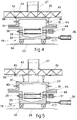
- the movable insulated conveyors 19 according to the invention (Fig.4) comprise a lower supporting base 32, on which the conveyor rollers 33 are supported at their ends.
- the segment of slab 31 is conveyed on the rollers 33.
- the lower supporting base 32 is associated with wheels 34, which run on suitably conformed rails 35, conformed as an arc of a circle for instance, for the lateral rotary movement to be imparted to the movable insulated conveyor 19.
- the actuation of the movement of the lower supporting base 32 is provided by a jack 36 in this case.
- Actuation of the jack 36 is governed by a signal announcing that the whole segment of the thin slab 31 is positioned within the movable insulated conveyor 19 and that any inlet doors present have been closed.
- rollers 33 are cooled by a continuous flow of cooling fluid under pressure and include cooling fluid delivery means 37 and cooling fluid outlet means 38 to create a cooling circuit.
- the lower supporting base 32 cooperates at its upper end with an insulated hood 20 in creating an inner heating and temperature-maintaining chamber 41.
- the sidewalls of the insulated hood 20 are equipped in this case with a plurality of heating means consisting of burners 40.
- the insulated hood 20 is immovably fitted to a carrying structure 42 and always stays in that position even during movement of the lower supporting base 32.
- the carrying structure 42 is of a known type and can be of any type. At least conduits 43 to feed the burners 40 are secured to the carrying structure 42.
- this layout enables a much lighter structure to be moved, with the resulting advantages of speed of performance, accuracy of alignment, less power employed, etc.
- conduits 43 to feed the burners 40 and a fumes aspiration stack 27 do not have to follow the movement of the lower supporting base 32, thus making the whole structure much more versatile and easy to handle.
- the lower supporting base 32 and the insulated hood 20 comprise mating jutting edges 44 and 45 protruding outwards from the heating and temperature-maintaining chamber 41 for the purpose of keeping the segment of the slab 31 covered at least partly by the insulated hood 20 within a certain range of lateral displacement of the lower supporting base 32.
- the jutting edges 44-45 have the purpose also of forming a protected seating for the roller cooling means 37-38 or for the burner feeder conduits 40 and also serve to maintain the temperature in the heating and temperature-maintaining chamber 41.
- the insulated hood 20 can also possess the substantially trapezoidal conformation shown in Fig.1 so as to achieve a still better protective condition.
- the insulated hood 20 is associated with the carrying structure 42 through jacks 39, which enable the hood 20 to be raised and lowered in relation to the lower supporting base 32.
- the insulated hood 20 may be lifted when the lower supporting base 32 has to be moved into alignment with one or the other of the stationary 15 or movable 16 tunnel furnaces positioned upstream or with other downstream processing units of the rolling line 10. This lessens the possibility of impacts between the insulated hood 20 and the lower supporting base 32 during movements of the latter, while retaining at the same time an excellent closure.
- the insulated hood 20 is then lowered onto the lower supporting base 32 when the latter 32 takes up again a stationary position for the passage of the segment of slab 31.
- the movable insulated conveyors 19 and also the movable tunnel furnaces 16 can be associated momentarily with tunnel furnaces 18 having a storage function; these storage tunnel furnaces 18 are positioned at the sides of the casting lines 11.
- the storage tunnel furnaces 18, if they are associated with rotary movable insulated conveyors 19, are arranged in the manner of spokes circumferentially about the axis of rotation 17 of the movable insulated conveyors 19.
- the storage tunnel furnaces 18 have several purposes.
- a first purpose may be to act as a temporary parking means for segments of slab 31 in the event of problems downstream, for instance when the rolls of the rolling train 12 have to be replaced without stopping the working of the casting machines 13.
- the storage tunnel furnaces 18 are employed for the performance of special processes or inspections on the segments of slab 31 before the segments 31 are sent to the rolling train 12.
- at least one storage tunnel furnace 18 can be associated with a checking and inspection station.
- At least one storage tunnel furnace 18 is associated with a conditioning unit 25 able to remove material in the hot state from the surface of the segment of slab 31 within the storage tunnel furnace 18 so as to eliminate any surface defects and to ready the segment 31 for rolling.
- At least one storage tunnel furnace 18 is associated with a unit 21 that shears to size and/or crops the leading and trailing ends of the slab.
- At least one storage tunnel furnace 18 is associated with a temperature-maintaining furnace, which can store at least two slabs positioned side by side or in line and having a thickness between 75 and 200 millimetres.
- the storage tunnel furnace 18 can be used also as a pre-heating furnace 29.
- each movable insulated conveyor 19 can cooperate with two or more storage tunnel furnaces 18.
- the movable insulated conveyors 19, movable tunnel furnaces 16 and storage tunnel furnaces 18 are equipped with doors which can be opened for the passage of segments of slab 31 and which close when the whole segment 31 is inside so as to prevent dispersion of heat.
- the movable tunnel furnaces 16 and storage tunnel furnaces 18 can also include insulator means and/or be equipped with heating and temperature-maintaining means.
- the floor of the movable tunnel furnaces 16 and of the storage tunnel furnaces 18 is conformed with rollers, which are advantageously but not necessarily cooled, to hold small dimensions of segments of slab, for instance with thicknesses between 30 and about 70 millimetres but in some cases even up to 100 millimetres.
- the floor of the movable insulated conveyors 19, movable tunnel furnaces 16 and storage tunnel furnaces 18 may be conformed with walking beams.
- the rolling line 10 downstream of the last movable insulated conveyor 19 may include an induction furnace 22, which ensures a speedy increase of the temperature of the slab 31; this induction furnace 22 is installed upstream of a temperature-equalisation furnace 23, which has the task of stabilising and making uniform in depth the temperature of the segments 31 passing through.
- At least one descaling unit 26 may possibly be included between the induction furnace 22 and the temperature-equalisation furnace 23.
- the rolling train 12 is located at the outlet of the temperature-equalisation furnace 23 and may cooperate downstream, and possibly also upstream, if it is of a reversible type, with coiling units 24.
Landscapes
- Engineering & Computer Science (AREA)
- Chemical & Material Sciences (AREA)
- Mechanical Engineering (AREA)
- Metallurgy (AREA)
- Thermal Sciences (AREA)
- Physics & Mathematics (AREA)
- Crystallography & Structural Chemistry (AREA)
- Materials Engineering (AREA)
- General Engineering & Computer Science (AREA)
- Organic Chemistry (AREA)
- Heat Treatments In General, Especially Conveying And Cooling (AREA)
- Tunnel Furnaces (AREA)
- Processing And Handling Of Plastics And Other Materials For Molding In General (AREA)
- Metal Rolling (AREA)
- Devices For Post-Treatments, Processing, Supply, Discharge, And Other Processes (AREA)
- Types And Forms Of Lifts (AREA)
- Aiming, Guidance, Guns With A Light Source, Armor, Camouflage, And Targets (AREA)
- Refuse Collection And Transfer (AREA)
Claims (18)
- Convoyeur isolé mobile pour la coulée continue de brames, de billettes, de blooms ou d'autres produits, qui est installé en ligne avec une installation de coulée continue (13) comprenant au moins deux lignes de coulée (11a-11b), au moins une cisaille (14) et un premier four-tunnel immobile (15) pour recevoir et accélérer des segments de brames (31) disposés entre l'installation de coulée continue (13) et un train de laminage (12), un four-tunnel mobile (16) étant éventuellement inclus à la suite du four-tunnel immobile (15), le convoyeur isolé mobile (19) étant caractérisé en ce qu'au moins l'un des convoyeurs isolés mobiles (19) est disposé à la suite du four-tunnel immobile (15) et/ou en amont et en coopération directe avec le train de laminage (12), le convoyeur isolé mobile (19) comprenant une embase inférieure (32) pour supporter des rouleaux (33) transportant les segments de brames (31) et une hotte supérieure isolée et chauffée (20), qui, au moins dans la position de travail, est immobile latéralement et longitudinalement, l'embase de support inférieure (32) étant à même d'être orientée au moins latéralement autour d'un axe de rotation sensiblement vertical (17).
- Convoyeur isolé mobile selon la revendication 1, dans lequel la hotte supérieure isolée et chauffée (20) est immobile verticalement.
- Convoyeur isolé mobile selon la revendication 1, dans lequel la hotte supérieure isolée et chauffée (20) peut être déplacée verticalement d'une position abaissée pour la fermeture de l'embase de support inférieure (32) vers une position relevée où il n'y a pas de contact avec l'embase de support inférieure (32).
- Convoyeur isolé mobile selon l'une quelconque des revendications précédentes, dans lequel la hotte supérieure isolée et chauffée (20) est associée à des moyens de chauffage à brûleurs (40).
- Convoyeur isolé mobile selon l'une quelconque des revendications précédentes, dans lequel la hotte supérieure isolée et chauffée (20) est associée à une cheminée d'aspiration des fumées (27).
- Convoyeur isolé mobile selon l'une quelconque des revendications précédentes, dans lequel l'axe de rotation vertical (17) de l'embase de support inférieure (32) est situé sensiblement au centre de la longueur de cette embase (32), la cheminée (27) étant coaxiale avec cet axe (17).
- Convoyeur isolé mobile selon l'une quelconque des revendications 1 à 5 incluse, dans lequel l'axe de rotation vertical (17) de l'embase de support inférieure (32) est disposé au voisinage de son extrémité la plus proche du four-tunnel immobile (15) ou du train de laminage (12).
- Convoyeur isolé mobile selon l'une quelconque des revendications précédentes, qui a au moins une première position sur le même axe que le four-tunnel immobile (15) ou que le train de laminage (12), et au moins une deuxième position faisant un angle avec la première position et situé sur le même axe que le four-tunnel mobile (16) se trouvant dans une position faisant un angle avec ce dernier axe, ou qu'un autre convoyeur isolé mobile (19) dans sa deuxième position angulaire, ou que le four-tunnel de stockage (18).
- Convoyeur isolé mobile selon l'une quelconque des revendications précédentes, qui coopère avec au moins un four-tunnel de stockage (18) associé à une unité (21) pour cisailler à dimensions et/ou ébouter les brames (31).
- Convoyeur isolé mobile selon l'une quelconque des revendications précédentes, qui coopère avec au moins un four-tunnel de stockage (18) associé à une unité de conditionnement à chaud (25).
- Convoyeur isolé mobile selon l'une quelconque des revendications précédentes, qui coopère avec au moins un four-tunnel de stockage (18) associé à un poste d'inspection.
- Convoyeur isolé mobile selon l'une quelconque des revendications précédentes, qui coopère avec au moins un four-tunnel de stockage (18) associé à un magasin (28) de produits froids.
- Convoyeur isolé mobile selon l'une quelconque des revendications précédentes, qui coopère avec au moins un four-tunnel de stockage (18) jouant le rôle d'un four de pré-chauffage (29).
- Convoyeur isolé mobile selon l'une quelconque des revendications précédentes, qui coopère en aval avec un four à induction (22) suivi d'un four d'égalisation de la température (23).
- Convoyeur isolé mobile selon l'une quelconque des revendications précédentes, qui coopère en aval avec au moins une unité de décalaminage (26).
- Convoyeur isolé mobile selon l'une quelconque des revendications précédentes, qui comprend, à ses extrémités, des portes ayant une position d'ouverture et une position de fermeture, les positions d'ouverture et de fermeture étant en corrélation avec les positions d'ouverture et de fermeture respectives des fours-tunnels immobiles (15), des fours-tunnels mobiles (16) et des fours-tunnels de stockage (18) associés au convoyeur isolé mobile (19) de temps à autre.
- Convoyeur isolé mobile selon l'une quelconque des revendications précédentes, dont au moins une partie du plancher est conformée avec des rouleaux refroidis (33).
- Convoyeur isolé mobile selon l'une quelconque des revendications 1 à 16 incluse, dont au moins une partie du plancher est conformée avec des longerons mobiles.
Applications Claiming Priority (2)
| Application Number | Priority Date | Filing Date | Title |
|---|---|---|---|
| ITUD930210A IT1262220B (it) | 1993-10-19 | 1993-10-19 | Via di trasporto mobile coibentata per colata continua di bramme |
| ITUD930210 | 1993-10-19 |
Publications (2)
| Publication Number | Publication Date |
|---|---|
| EP0648552A1 EP0648552A1 (fr) | 1995-04-19 |
| EP0648552B1 true EP0648552B1 (fr) | 1997-12-10 |
Family
ID=11421406
Family Applications (1)
| Application Number | Title | Priority Date | Filing Date |
|---|---|---|---|
| EP94115946A Expired - Lifetime EP0648552B1 (fr) | 1993-10-19 | 1994-10-10 | Convoyeur isolé mobile pour la coulée continue de brames |
Country Status (6)
| Country | Link |
|---|---|
| US (1) | US6018855A (fr) |
| EP (1) | EP0648552B1 (fr) |
| AT (1) | ATE160955T1 (fr) |
| DE (1) | DE69407253T2 (fr) |
| ES (1) | ES2109575T3 (fr) |
| IT (1) | IT1262220B (fr) |
Cited By (1)
| Publication number | Priority date | Publication date | Assignee | Title |
|---|---|---|---|---|
| WO2008025325A1 (fr) * | 2006-09-01 | 2008-03-06 | Sms Demag Ag | Dispositif de maintien à température de brames sortant d'une installation de coulée continue |
Families Citing this family (17)
| Publication number | Priority date | Publication date | Assignee | Title |
|---|---|---|---|---|
| JP3413819B2 (ja) * | 1995-01-19 | 2003-06-09 | 石川島播磨重工業株式会社 | 連続鋼板製造設備 |
| DE19621259A1 (de) * | 1996-05-25 | 1997-11-27 | Schloemann Siemag Ag | Verfahren und Anlage zur Herstellung von Edelstahl- oder Kohlenstoffstahlblech aus durch Strangguß erzeugten Dünnbrammen |
| DE19649295A1 (de) * | 1996-11-28 | 1998-06-04 | Schloemann Siemag Ag | Warmwalzanlage |
| DE19712212A1 (de) * | 1997-03-24 | 1998-10-01 | Schloemann Siemag Ag | Verfahren und Anlage zum Auswalzen von Warmbreitband aus stranggegossenen Brammen |
| IT1294632B1 (it) | 1997-09-15 | 1999-04-12 | Danieli Off Mecc | Procedimento di trasformazione impianto di laminazione |
| AT407348B (de) | 1997-10-10 | 2001-02-26 | Voest Alpine Ind Anlagen | Verfahren zum herstellen eines warmgewalzten produktes und anlage zur durchführung des verfahrens |
| IT1296715B1 (it) * | 1997-11-11 | 1999-07-15 | Danieli Off Mecc | Procedimento di controllo assialita' per bramme uscenti da colata continua e relativo dispositivo |
| DE10004117A1 (de) * | 2000-01-31 | 2001-08-02 | Loi Thermprocess Gmbh | Ofenanlage |
| KR100354512B1 (ko) * | 2000-10-30 | 2002-09-28 | 포철산기주식회사 | 슬라브 파일 컨베이어의 변형방지장치 |
| JP2009227809A (ja) * | 2008-03-21 | 2009-10-08 | Fujifilm Corp | 親水性組成物及び親水性処理部材 |
| DE102010050647A1 (de) * | 2009-11-21 | 2011-05-26 | Sms Siemag Aktiengesellschaft | Anlage und Verfahren zum Gießen und Walzen von Metall |
| DE102009060824A1 (de) * | 2009-12-29 | 2011-06-30 | SMS Siemag AG, 40237 | Transportvorrichtung für Brammen |
| IT1400002B1 (it) * | 2010-05-10 | 2013-05-09 | Danieli Off Mecc | Procedimento ed impianto per la produzione di prodotti laminati piani |
| IT1402240B1 (it) * | 2010-07-21 | 2013-08-28 | Danieli Off Mecc | Apparecchiatura di mantenimento in temperatura e/o eventuale riscaldo di prodotti metallici lunghi e relativo procedimento |
| GB2506395A (en) * | 2012-09-28 | 2014-04-02 | Siemens Plc | Roller table and method of rolling a Material |
| DE102016217720A1 (de) * | 2016-09-16 | 2018-03-22 | Sms Group Gmbh | Verfahrbarer Wärmedämmwagen bei der Metallbearbeitung |
| EP4724215A1 (fr) * | 2023-06-09 | 2026-04-15 | SMS Group GmbH | Dispositif et procédé pour chauffer une brame |
Family Cites Families (8)
| Publication number | Priority date | Publication date | Assignee | Title |
|---|---|---|---|---|
| DE534578C (de) * | 1929-12-22 | 1931-09-29 | Naamlooze Vennootschap Mij Tot | Kuehlofen fuer absatzweise hergestellte Glasplatten |
| DE1130459B (de) * | 1956-08-21 | 1962-05-30 | Kraft Industrieofenbau Ges Mit | Drehherdofen |
| US3385579A (en) * | 1965-12-08 | 1968-05-28 | Westinghouse Electric Corp | Slab heating apparatus |
| JPS5545530A (en) * | 1978-09-25 | 1980-03-31 | Chiyoda Koutetsu Kogyo Kk | Direct rolling equipment for continuous casting having moving type continuous heating furnaces |
| US4420029A (en) * | 1979-04-27 | 1983-12-13 | Nippon Steel Corporation | Apparatus for blocking escape of heat in hot slabs manufactured on continuous casting machines |
| JPS58168416A (ja) * | 1982-03-31 | 1983-10-04 | Nippon Kokan Kk <Nkk> | 連続鋳造設備における鋳片加熱装置 |
| DE3901582A1 (de) * | 1989-01-20 | 1990-08-02 | Schloemann Siemag Ag | Stranggiessanlage |
| DE4041205A1 (de) * | 1990-12-21 | 1992-06-25 | Schloemann Siemag Ag | Verfahren und anlage zum auswalzen von warmbreitband aus stranggegossenen duennbrammen |
-
1993
- 1993-10-19 IT ITUD930210A patent/IT1262220B/it active IP Right Grant
-
1994
- 1994-10-10 EP EP94115946A patent/EP0648552B1/fr not_active Expired - Lifetime
- 1994-10-10 ES ES94115946T patent/ES2109575T3/es not_active Expired - Lifetime
- 1994-10-10 DE DE69407253T patent/DE69407253T2/de not_active Expired - Fee Related
- 1994-10-10 AT AT94115946T patent/ATE160955T1/de not_active IP Right Cessation
- 1994-10-17 US US08/323,923 patent/US6018855A/en not_active Expired - Fee Related
Cited By (2)
| Publication number | Priority date | Publication date | Assignee | Title |
|---|---|---|---|---|
| WO2008025325A1 (fr) * | 2006-09-01 | 2008-03-06 | Sms Demag Ag | Dispositif de maintien à température de brames sortant d'une installation de coulée continue |
| CN101512279B (zh) * | 2006-09-01 | 2011-11-09 | Sms西马克股份公司 | 用于由连续铸坯机排出的板坯的保温的装置以及辊道装置 |
Also Published As
| Publication number | Publication date |
|---|---|
| IT1262220B (it) | 1996-06-19 |
| DE69407253T2 (de) | 1998-06-25 |
| DE69407253D1 (de) | 1998-01-22 |
| ES2109575T3 (es) | 1998-01-16 |
| US6018855A (en) | 2000-02-01 |
| ITUD930210A1 (it) | 1995-04-19 |
| ATE160955T1 (de) | 1997-12-15 |
| EP0648552A1 (fr) | 1995-04-19 |
| ITUD930210A0 (it) | 1993-10-19 |
Similar Documents
| Publication | Publication Date | Title |
|---|---|---|
| EP0648552B1 (fr) | Convoyeur isolé mobile pour la coulée continue de brames | |
| EP0625383B1 (fr) | Ligne de fabrication de bandes et/ou feuilles métalliques | |
| EP2252417B1 (fr) | Appareil de coulée en bande destiné à installer et à changer rapidement des rouleaux lamineurs | |
| AU2006337956B2 (en) | Roller hearth furnace for heating and/or temperature equalization of steel or steel alloy continuously cast products and its arrangement upstream of a hot strip finishing train | |
| EP0302257B1 (fr) | Four d'egalisation pour billettes coulées en continu | |
| JP2002538295A (ja) | 装入物を予熱し溶融し精錬し鋳造する連続電気炉製鋼 | |
| AU737631B2 (en) | Method to control the axial position of slabs emerging from continuous casting and relative device | |
| EP0499851B2 (fr) | Système à tunnel pour lier un laminoir de bandes à chaud au dispositifs de coulée en continu de lames minces | |
| US5117545A (en) | Plant to roll flat products | |
| CA2313538C (fr) | Dispositif et procede servant a fabriquer une bande d'acier | |
| KR101504671B1 (ko) | 안내 및 수용 세그먼트와 그를 포함하는 연속 주조 장치 및 연속 주조 방법 | |
| JPH059185B2 (fr) | ||
| CN100509193C (zh) | 用于移动金属物料的装置 | |
| CN1307014C (zh) | 连续金属带铸造装置 | |
| US4909303A (en) | Steel manufacturing system, particularly a mini-steel plant | |
| CN101512279A (zh) | 用于由连续铸坯机排出的板坯的保温的装置 | |
| US3974874A (en) | Continuous casting plant | |
| EP0822015B1 (fr) | Procédé d'exploitation d'un refroidisseur isolé et refroidisseur associé | |
| CN114472555A (zh) | 一种双线加工生产系统 | |
| US5333366A (en) | Installation for manufacture of hot rolled steel strips | |
| JPS61279349A (ja) | 高温の鋳造片を移送する装置 | |
| AU651694B2 (en) | Technological line for production of metal strip and a transporting device therefor | |
| US4279408A (en) | Apparatus for changing tuyeres on a blast furnace | |
| SU1576227A1 (ru) | Литейно-прокатный агрегат | |
| CA2245950C (fr) | Convoyeur de sortie descendant pour four a poussoir |
Legal Events
| Date | Code | Title | Description |
|---|---|---|---|
| PUAI | Public reference made under article 153(3) epc to a published international application that has entered the european phase |
Free format text: ORIGINAL CODE: 0009012 |
|
| AK | Designated contracting states |
Kind code of ref document: A1 Designated state(s): AT BE DE ES FR GB IT SE |
|
| 17P | Request for examination filed |
Effective date: 19951010 |
|
| GRAG | Despatch of communication of intention to grant |
Free format text: ORIGINAL CODE: EPIDOS AGRA |
|
| 17Q | First examination report despatched |
Effective date: 19970324 |
|
| GRAH | Despatch of communication of intention to grant a patent |
Free format text: ORIGINAL CODE: EPIDOS IGRA |
|
| GRAH | Despatch of communication of intention to grant a patent |
Free format text: ORIGINAL CODE: EPIDOS IGRA |
|
| GRAA | (expected) grant |
Free format text: ORIGINAL CODE: 0009210 |
|
| ITF | It: translation for a ep patent filed | ||
| AK | Designated contracting states |
Kind code of ref document: B1 Designated state(s): AT BE DE ES FR GB IT SE |
|
| REF | Corresponds to: |
Ref document number: 160955 Country of ref document: AT Date of ref document: 19971215 Kind code of ref document: T |
|
| ET | Fr: translation filed | ||
| REG | Reference to a national code |
Ref country code: ES Ref legal event code: FG2A Ref document number: 2109575 Country of ref document: ES Kind code of ref document: T3 |
|
| REF | Corresponds to: |
Ref document number: 69407253 Country of ref document: DE Date of ref document: 19980122 |
|
| PLBQ | Unpublished change to opponent data |
Free format text: ORIGINAL CODE: EPIDOS OPPO |
|
| PLBI | Opposition filed |
Free format text: ORIGINAL CODE: 0009260 |
|
| PLBF | Reply of patent proprietor to notice(s) of opposition |
Free format text: ORIGINAL CODE: EPIDOS OBSO |
|
| 26 | Opposition filed |
Opponent name: SMS SCHLOEMANN-SIEMAG AG Effective date: 19980909 |
|
| PLBF | Reply of patent proprietor to notice(s) of opposition |
Free format text: ORIGINAL CODE: EPIDOS OBSO |
|
| PLBO | Opposition rejected |
Free format text: ORIGINAL CODE: EPIDOS REJO |
|
| PLBN | Opposition rejected |
Free format text: ORIGINAL CODE: 0009273 |
|
| STAA | Information on the status of an ep patent application or granted ep patent |
Free format text: STATUS: OPPOSITION REJECTED |
|
| 27O | Opposition rejected |
Effective date: 20000312 |
|
| REG | Reference to a national code |
Ref country code: GB Ref legal event code: IF02 |
|
| PGFP | Annual fee paid to national office [announced via postgrant information from national office to epo] |
Ref country code: SE Payment date: 20030925 Year of fee payment: 10 Ref country code: BE Payment date: 20030925 Year of fee payment: 10 |
|
| PGFP | Annual fee paid to national office [announced via postgrant information from national office to epo] |
Ref country code: GB Payment date: 20030929 Year of fee payment: 10 |
|
| PGFP | Annual fee paid to national office [announced via postgrant information from national office to epo] |
Ref country code: ES Payment date: 20031010 Year of fee payment: 10 |
|
| PG25 | Lapsed in a contracting state [announced via postgrant information from national office to epo] |
Ref country code: GB Free format text: LAPSE BECAUSE OF NON-PAYMENT OF DUE FEES Effective date: 20041010 |
|
| PG25 | Lapsed in a contracting state [announced via postgrant information from national office to epo] |
Ref country code: SE Free format text: LAPSE BECAUSE OF NON-PAYMENT OF DUE FEES Effective date: 20041011 Ref country code: ES Free format text: LAPSE BECAUSE OF NON-PAYMENT OF DUE FEES Effective date: 20041011 |
|
| PG25 | Lapsed in a contracting state [announced via postgrant information from national office to epo] |
Ref country code: BE Free format text: LAPSE BECAUSE OF NON-PAYMENT OF DUE FEES Effective date: 20041031 |
|
| BERE | Be: lapsed |
Owner name: *DANIELI & C. OFFICINE MECCANICHE S.P.A. Effective date: 20041031 |
|
| EUG | Se: european patent has lapsed | ||
| GBPC | Gb: european patent ceased through non-payment of renewal fee |
Effective date: 20041010 |
|
| REG | Reference to a national code |
Ref country code: ES Ref legal event code: FD2A Effective date: 20041011 |
|
| BERE | Be: lapsed |
Owner name: *DANIELI & C. OFFICINE MECCANICHE S.P.A. Effective date: 20041031 |
|
| PGFP | Annual fee paid to national office [announced via postgrant information from national office to epo] |
Ref country code: DE Payment date: 20081030 Year of fee payment: 15 |
|
| PGFP | Annual fee paid to national office [announced via postgrant information from national office to epo] |
Ref country code: AT Payment date: 20080924 Year of fee payment: 15 |
|
| PGFP | Annual fee paid to national office [announced via postgrant information from national office to epo] |
Ref country code: IT Payment date: 20081016 Year of fee payment: 15 |
|
| PGFP | Annual fee paid to national office [announced via postgrant information from national office to epo] |
Ref country code: FR Payment date: 20081028 Year of fee payment: 15 |
|
| REG | Reference to a national code |
Ref country code: FR Ref legal event code: ST Effective date: 20100630 |
|
| PG25 | Lapsed in a contracting state [announced via postgrant information from national office to epo] |
Ref country code: FR Free format text: LAPSE BECAUSE OF NON-PAYMENT OF DUE FEES Effective date: 20091102 Ref country code: DE Free format text: LAPSE BECAUSE OF NON-PAYMENT OF DUE FEES Effective date: 20100501 |
|
| PG25 | Lapsed in a contracting state [announced via postgrant information from national office to epo] |
Ref country code: AT Free format text: LAPSE BECAUSE OF NON-PAYMENT OF DUE FEES Effective date: 20091010 |
|
| PG25 | Lapsed in a contracting state [announced via postgrant information from national office to epo] |
Ref country code: IT Free format text: LAPSE BECAUSE OF NON-PAYMENT OF DUE FEES Effective date: 20091010 |