EP0647986A1 - Broche de contact pour connexions à fiches - Google Patents
Broche de contact pour connexions à fiches Download PDFInfo
- Publication number
- EP0647986A1 EP0647986A1 EP94114228A EP94114228A EP0647986A1 EP 0647986 A1 EP0647986 A1 EP 0647986A1 EP 94114228 A EP94114228 A EP 94114228A EP 94114228 A EP94114228 A EP 94114228A EP 0647986 A1 EP0647986 A1 EP 0647986A1
- Authority
- EP
- European Patent Office
- Prior art keywords
- contact pin
- pairs
- circumference
- noses
- receiving opening
- Prior art date
- Legal status (The legal status is an assumption and is not a legal conclusion. Google has not performed a legal analysis and makes no representation as to the accuracy of the status listed.)
- Granted
Links
Images
Classifications
-
- H—ELECTRICITY
- H01—ELECTRIC ELEMENTS
- H01R—ELECTRICALLY-CONDUCTIVE CONNECTIONS; STRUCTURAL ASSOCIATIONS OF A PLURALITY OF MUTUALLY-INSULATED ELECTRICAL CONNECTING ELEMENTS; COUPLING DEVICES; CURRENT COLLECTORS
- H01R13/00—Details of coupling devices of the kinds covered by groups H01R12/70 or H01R24/00 - H01R33/00
- H01R13/40—Securing contact members in or to a base or case; Insulating of contact members
- H01R13/405—Securing in non-demountable manner, e.g. moulding, riveting
- H01R13/41—Securing in non-demountable manner, e.g. moulding, riveting by frictional grip in grommet, panel or base
Definitions
- the invention relates to a contact pin for plug connections, which is provided with impressions on its periphery and can be inserted into a receiving opening of a plastic body and fastened therein by clamping, the impressions being pressed into the inner wall of the receiving opening.
- Such a contact pin is known from DE-OS 25 23 448.
- This contact pin is formed with a holding shaft with a square cross section, into which circumferential transverse ribs, which are inclined at an angle to the longitudinal axis of the pin and flattened at the highest points, are embossed.
- the invention has for its object to achieve a sufficient tightness with a contact pin of the type mentioned in a reproducible manufacturing process and to ensure the highest possible holding forces.
- a contact pin of the type mentioned in accordance with the invention in that the impressions are provided at two points located one behind the other in the longitudinal direction of the contact pin and are each attached in pairs at two opposite points on the circumference of the contact pin and as beyond the circumference of the contact pin protruding pairs of lugs are executed, and that these pairs of lugs each have a rising opposite to the direction of insertion of the contact pin contour.
- a contact pin of this type is stamped at two adjacent points in the longitudinal direction with two sides stamped on its circumference Nose pairs, that is to say with a total of four pairs of noses, which are attached in a simple manner in a reproducible manufacturing process by means of stamping dies, which print the material of the contact pin beyond its original circumference to the outside.
- the pairs of lugs have a contour which rises in the opposite direction to the direction in which the contact pin is inserted, with nose flanks which are inclined at an angle to the longitudinal axis of the contact pin and a steep rear flank.
- the rear nose pairs in the insertion direction have a greater height than the front nose pairs. This measure ensures the secure fit of one Contact pin in the receiving opening of a plastic part additionally improved.
- This advantage can also be achieved in a second exemplary embodiment of a contact pin according to the invention in that the pairs of noses at one point of the contact pin are offset by 90 ° relative to the nose pairs at the other point of the contact pin on the circumference of the contact pin.
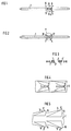
- the contact pin has, for example, a square cross-sectional shape with an edge length of, for example, 0.6 mm and is provided with embossments on its circumference at two points lying one behind the other in the longitudinal direction of the contact pin.
- embossments on its circumference at two points lying one behind the other in the longitudinal direction of the contact pin.
- these are each attached in pairs at two mutually opposite locations on the circumference of the contact pin and are designed as pairs of noses projecting beyond the circumference of the contact pin, these pairs of noses each having a contour that increases in the opposite direction to the direction in which the contact pin is inserted.
- 1 to 7 accordingly has two pairs of lugs 3 and 3 'at a first location at two mutually opposite locations and also at two at a closely adjacent second location opposite points - based on the circumference of the contact pin - lying in the same angular position - each two further pairs of noses 4 or 4 ', the two noses of a pair of noses 3, 3', 4 or 4 '- as is particularly clear from the enlarged view 4 can be seen - are impressed into the contact pin from above and below.
- the pairs of lugs have a contour which rises in the opposite direction to the direction in which the contact pin 1 is inserted, so that they protrude beyond the original circumference of the contact pin with nose flanks 5 inclined obliquely to the longitudinal axis of the contact pin and a steep retaining flank 6 transverse to the longitudinal axis of the contact pin.
- the rear lug pairs 4,4 'of the contact pin 1 have a greater height than the front lug pairs 3,3', so that the contact pin 1 in section BB has a somewhat larger cross section than section AA .
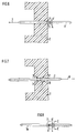
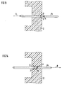
- a contact pin 1 is inserted into a receiving opening of a plastic part 2, for example into a pin strip, in a direction of insertion indicated by an arrow 7. In its end position shown in FIG. 7, the contact pin 1 is then securely anchored in the plastic part 2 in the event of forces occurring in the direction of an arrow 8 (direction of holding force) due to the barb-like pairs of lugs.
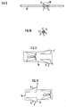
- the second embodiment of a contact pin 1 a shown in FIGS. 8 to 14 differs from the embodiment shown in FIGS. 1 to 7 only in the angular position of the pairs of noses 3, 3 'and 4, 4' in relation to the circumference of the contact pin. .
- the 7 rear pairs of noses 4,4 'in the direction of insertion are offset by 90 ° with respect to the front pairs of noses 3,3', the front and rear pairs of noses 3,3 'and 4,4' being able to have the same height. Otherwise it is Contour and the arrangement of the pairs of noses 3,3 'and 4,4' identical to the embodiment according to FIGS. 1 to 7.
Landscapes
- Connector Housings Or Holding Contact Members (AREA)
Applications Claiming Priority (2)
| Application Number | Priority Date | Filing Date | Title |
|---|---|---|---|
| DE9314676U DE9314676U1 (de) | 1993-09-28 | 1993-09-28 | Kontaktstift für Steckverbindungen |
| DE9314676U | 1993-09-28 |
Publications (2)
| Publication Number | Publication Date |
|---|---|
| EP0647986A1 true EP0647986A1 (fr) | 1995-04-12 |
| EP0647986B1 EP0647986B1 (fr) | 1996-11-27 |
Family
ID=6898670
Family Applications (1)
| Application Number | Title | Priority Date | Filing Date |
|---|---|---|---|
| EP94114228A Expired - Lifetime EP0647986B1 (fr) | 1993-09-28 | 1994-09-09 | Broche de contact pour connexions à fiches |
Country Status (3)
| Country | Link |
|---|---|
| EP (1) | EP0647986B1 (fr) |
| DE (2) | DE9314676U1 (fr) |
| ES (1) | ES2094607T3 (fr) |
Cited By (4)
| Publication number | Priority date | Publication date | Assignee | Title |
|---|---|---|---|---|
| US5692928A (en) * | 1996-05-10 | 1997-12-02 | Molex Incorporated | Electrical connector having terminals with improved retention means |
| EP0854542A2 (fr) * | 1997-01-13 | 1998-07-22 | Framatome Connectors International | Broche de contact ayant des ailes d'ancrage orientées dans des directions opposées et élement |
| US5807142A (en) * | 1996-05-10 | 1998-09-15 | Molex Incorporated | Electrical connector having terminals with improved retention means |
| WO2018215385A1 (fr) * | 2017-05-23 | 2018-11-29 | Te Connectivity Germany Gmbh | Broche de contact |
Citations (3)
| Publication number | Priority date | Publication date | Assignee | Title |
|---|---|---|---|---|
| GB1087422A (en) * | 1964-02-27 | 1967-10-18 | Malco Mfg Company Inc | Electrical terminal |
| US5035656A (en) * | 1990-05-15 | 1991-07-30 | E. I. Du Pont De Nemours And Company | Connector, circuit board contact element and retention portion |
| US5147227A (en) * | 1991-10-17 | 1992-09-15 | Amp Incorporated | Terminal retention device |
-
1993
- 1993-09-28 DE DE9314676U patent/DE9314676U1/de not_active Expired - Lifetime
-
1994
- 1994-09-09 DE DE59401150T patent/DE59401150D1/de not_active Expired - Lifetime
- 1994-09-09 ES ES94114228T patent/ES2094607T3/es not_active Expired - Lifetime
- 1994-09-09 EP EP94114228A patent/EP0647986B1/fr not_active Expired - Lifetime
Patent Citations (3)
| Publication number | Priority date | Publication date | Assignee | Title |
|---|---|---|---|---|
| GB1087422A (en) * | 1964-02-27 | 1967-10-18 | Malco Mfg Company Inc | Electrical terminal |
| US5035656A (en) * | 1990-05-15 | 1991-07-30 | E. I. Du Pont De Nemours And Company | Connector, circuit board contact element and retention portion |
| US5147227A (en) * | 1991-10-17 | 1992-09-15 | Amp Incorporated | Terminal retention device |
Cited By (8)
| Publication number | Priority date | Publication date | Assignee | Title |
|---|---|---|---|---|
| US5692928A (en) * | 1996-05-10 | 1997-12-02 | Molex Incorporated | Electrical connector having terminals with improved retention means |
| US5807142A (en) * | 1996-05-10 | 1998-09-15 | Molex Incorporated | Electrical connector having terminals with improved retention means |
| EP0854542A2 (fr) * | 1997-01-13 | 1998-07-22 | Framatome Connectors International | Broche de contact ayant des ailes d'ancrage orientées dans des directions opposées et élement |
| EP0854542A3 (fr) * | 1997-01-13 | 1999-10-13 | Framatome Connectors International | Broche de contact ayant des ailes d'ancrage orientées dans des directions opposées et élement |
| WO2018215385A1 (fr) * | 2017-05-23 | 2018-11-29 | Te Connectivity Germany Gmbh | Broche de contact |
| CN110651397A (zh) * | 2017-05-23 | 2020-01-03 | 泰连德国有限公司 | 接触销 |
| US11069996B2 (en) | 2017-05-23 | 2021-07-20 | Te Connectivity Germany Gmbh | Contact pin for plug connector having retaining elements |
| CN110651397B (zh) * | 2017-05-23 | 2021-08-10 | 泰连德国有限公司 | 接触销 |
Also Published As
| Publication number | Publication date |
|---|---|
| DE9314676U1 (de) | 1994-02-24 |
| EP0647986B1 (fr) | 1996-11-27 |
| DE59401150D1 (de) | 1997-01-09 |
| ES2094607T3 (es) | 1997-01-16 |
Similar Documents
| Publication | Publication Date | Title |
|---|---|---|
| DE4040748C2 (fr) | ||
| DE102007025111B4 (de) | Konnektor | |
| DE2409075A1 (de) | Elektrischer verbinder | |
| DE102009025722A1 (de) | Rastverbindungsanordnung | |
| DE19848563A1 (de) | Dichtungs-Haltestruktur | |
| DE19755497C1 (de) | Steuergerätegehäuse aus Kunststoff für ein Kraftfahrzeug | |
| DE19848289C2 (de) | Verriegelungsvorrichtung eines Kappenteils | |
| EP3488128B1 (fr) | Élément d'étanchéité pour la liaison étanche au fluide et électro-conductrice d'une première pièce et d'une deuxième pièce, ainsi qu'ensemble correspondant de pièces | |
| WO2021151426A1 (fr) | Boîtier rapporté | |
| EP0647986B1 (fr) | Broche de contact pour connexions à fiches | |
| DE4205974C1 (en) | Electrical plug connector with built-in latching for pins - provides section formed on housing that locates against pin flange and is held by latch stage | |
| AT1268U1 (de) | Sichtfenster | |
| DE102016220022B4 (de) | Kombination eines Steckers mit einem Deckel | |
| DE4323524C2 (de) | Dichtungsanordnung | |
| DE4301602C1 (de) | Elektrisches Steckverbindungsteil | |
| EP0703641A2 (fr) | Elément de connecteur électrique | |
| EP0691711B1 (fr) | Connecteur | |
| DE10248119B3 (de) | Steckkarte für elektronische Datenverarbeitungsgeräte | |
| DE60102546T2 (de) | Elektrischer Verbinder | |
| DE19639665A1 (de) | Beweglicher Verbindungsstecker mit Stützplattenverlängerung | |
| DE19720196C2 (de) | Messwerk | |
| EP0415136A1 (fr) | Insert pour connecteur à boîtier métallique | |
| DE60004607T2 (de) | Gehäuse für tafelmontierten elektrischen Verbinder vom Durchführungstyp | |
| DE10140243C1 (de) | Kuppelvorrichtung zum Verbinden zweier Steckelemente | |
| DE10029222A1 (de) | Elektrisches Installationsgerät |
Legal Events
| Date | Code | Title | Description |
|---|---|---|---|
| PUAI | Public reference made under article 153(3) epc to a published international application that has entered the european phase |
Free format text: ORIGINAL CODE: 0009012 |
|
| AK | Designated contracting states |
Kind code of ref document: A1 Designated state(s): BE DE ES FR GB IT SE |
|
| 17P | Request for examination filed |
Effective date: 19950504 |
|
| 17Q | First examination report despatched |
Effective date: 19951025 |
|
| GRAG | Despatch of communication of intention to grant |
Free format text: ORIGINAL CODE: EPIDOS AGRA |
|
| GRAH | Despatch of communication of intention to grant a patent |
Free format text: ORIGINAL CODE: EPIDOS IGRA |
|
| GRAH | Despatch of communication of intention to grant a patent |
Free format text: ORIGINAL CODE: EPIDOS IGRA |
|
| GRAA | (expected) grant |
Free format text: ORIGINAL CODE: 0009210 |
|
| AK | Designated contracting states |
Kind code of ref document: B1 Designated state(s): BE DE ES FR GB IT SE |
|
| REF | Corresponds to: |
Ref document number: 59401150 Country of ref document: DE Date of ref document: 19970109 |
|
| REG | Reference to a national code |
Ref country code: ES Ref legal event code: FG2A Ref document number: 2094607 Country of ref document: ES Kind code of ref document: T3 |
|
| ET | Fr: translation filed | ||
| ITF | It: translation for a ep patent filed |
Owner name: STUDIO JAUMANN |
|
| GBT | Gb: translation of ep patent filed (gb section 77(6)(a)/1977) |
Effective date: 19970130 |
|
| PLBE | No opposition filed within time limit |
Free format text: ORIGINAL CODE: 0009261 |
|
| STAA | Information on the status of an ep patent application or granted ep patent |
Free format text: STATUS: NO OPPOSITION FILED WITHIN TIME LIMIT |
|
| 26N | No opposition filed | ||
| PGFP | Annual fee paid to national office [announced via postgrant information from national office to epo] |
Ref country code: SE Payment date: 20000901 Year of fee payment: 7 |
|
| PGFP | Annual fee paid to national office [announced via postgrant information from national office to epo] |
Ref country code: ES Payment date: 20000926 Year of fee payment: 7 |
|
| PGFP | Annual fee paid to national office [announced via postgrant information from national office to epo] |
Ref country code: BE Payment date: 20001010 Year of fee payment: 7 |
|
| REG | Reference to a national code |
Ref country code: GB Ref legal event code: 732E |
|
| PG25 | Lapsed in a contracting state [announced via postgrant information from national office to epo] |
Ref country code: SE Free format text: LAPSE BECAUSE OF NON-PAYMENT OF DUE FEES Effective date: 20010910 Ref country code: ES Free format text: LAPSE BECAUSE OF NON-PAYMENT OF DUE FEES Effective date: 20010910 |
|
| PG25 | Lapsed in a contracting state [announced via postgrant information from national office to epo] |
Ref country code: BE Free format text: LAPSE BECAUSE OF NON-PAYMENT OF DUE FEES Effective date: 20010930 |
|
| REG | Reference to a national code |
Ref country code: GB Ref legal event code: IF02 |
|
| BERE | Be: lapsed |
Owner name: SIEMENS A.G. Effective date: 20010930 |
|
| EUG | Se: european patent has lapsed |
Ref document number: 94114228.3 |
|
| PGFP | Annual fee paid to national office [announced via postgrant information from national office to epo] |
Ref country code: GB Payment date: 20020808 Year of fee payment: 9 |
|
| PGFP | Annual fee paid to national office [announced via postgrant information from national office to epo] |
Ref country code: FR Payment date: 20020903 Year of fee payment: 9 |
|
| PG25 | Lapsed in a contracting state [announced via postgrant information from national office to epo] |
Ref country code: GB Free format text: LAPSE BECAUSE OF NON-PAYMENT OF DUE FEES Effective date: 20030909 |
|
| GBPC | Gb: european patent ceased through non-payment of renewal fee |
Effective date: 20030909 |
|
| REG | Reference to a national code |
Ref country code: ES Ref legal event code: FD2A Effective date: 20021011 |
|
| PG25 | Lapsed in a contracting state [announced via postgrant information from national office to epo] |
Ref country code: FR Free format text: LAPSE BECAUSE OF NON-PAYMENT OF DUE FEES Effective date: 20040528 |
|
| REG | Reference to a national code |
Ref country code: FR Ref legal event code: ST |
|
| PG25 | Lapsed in a contracting state [announced via postgrant information from national office to epo] |
Ref country code: IT Free format text: LAPSE BECAUSE OF NON-PAYMENT OF DUE FEES;WARNING: LAPSES OF ITALIAN PATENTS WITH EFFECTIVE DATE BEFORE 2007 MAY HAVE OCCURRED AT ANY TIME BEFORE 2007. THE CORRECT EFFECTIVE DATE MAY BE DIFFERENT FROM THE ONE RECORDED. Effective date: 20050909 |
|
| PGFP | Annual fee paid to national office [announced via postgrant information from national office to epo] |
Ref country code: DE Payment date: 20130927 Year of fee payment: 20 |
|
| REG | Reference to a national code |
Ref country code: DE Ref legal event code: R071 Ref document number: 59401150 Country of ref document: DE |
|
| PG25 | Lapsed in a contracting state [announced via postgrant information from national office to epo] |
Ref country code: DE Free format text: LAPSE BECAUSE OF EXPIRATION OF PROTECTION Effective date: 20140910 |