EP0647986A1 - Contact pin for plug connections - Google Patents
Contact pin for plug connections Download PDFInfo
- Publication number
- EP0647986A1 EP0647986A1 EP94114228A EP94114228A EP0647986A1 EP 0647986 A1 EP0647986 A1 EP 0647986A1 EP 94114228 A EP94114228 A EP 94114228A EP 94114228 A EP94114228 A EP 94114228A EP 0647986 A1 EP0647986 A1 EP 0647986A1
- Authority
- EP
- European Patent Office
- Prior art keywords
- contact pin
- pairs
- circumference
- noses
- receiving opening
- Prior art date
- Legal status (The legal status is an assumption and is not a legal conclusion. Google has not performed a legal analysis and makes no representation as to the accuracy of the status listed.)
- Granted
Links
- 238000003780 insertion Methods 0.000 claims abstract description 7
- 230000037431 insertion Effects 0.000 claims abstract description 7
- 210000001331 nose Anatomy 0.000 claims description 22
- 238000004519 manufacturing process Methods 0.000 description 2
- 239000000463 material Substances 0.000 description 2
- 238000004873 anchoring Methods 0.000 description 1
- 239000003795 chemical substances by application Substances 0.000 description 1
- 238000006073 displacement reaction Methods 0.000 description 1
- 230000004907 flux Effects 0.000 description 1
- 239000007788 liquid Substances 0.000 description 1
- 230000013011 mating Effects 0.000 description 1
- 238000000034 method Methods 0.000 description 1
- 239000003973 paint Substances 0.000 description 1
- 230000000630 rising effect Effects 0.000 description 1
- 238000007789 sealing Methods 0.000 description 1
- 238000005476 soldering Methods 0.000 description 1
Images
Classifications
-
- H—ELECTRICITY
- H01—ELECTRIC ELEMENTS
- H01R—ELECTRICALLY-CONDUCTIVE CONNECTIONS; STRUCTURAL ASSOCIATIONS OF A PLURALITY OF MUTUALLY-INSULATED ELECTRICAL CONNECTING ELEMENTS; COUPLING DEVICES; CURRENT COLLECTORS
- H01R13/00—Details of coupling devices of the kinds covered by groups H01R12/70 or H01R24/00 - H01R33/00
- H01R13/40—Securing contact members in or to a base or case; Insulating of contact members
- H01R13/405—Securing in non-demountable manner, e.g. moulding, riveting
- H01R13/41—Securing in non-demountable manner, e.g. moulding, riveting by frictional grip in grommet, panel or base
Definitions
- the invention relates to a contact pin for plug connections, which is provided with impressions on its periphery and can be inserted into a receiving opening of a plastic body and fastened therein by clamping, the impressions being pressed into the inner wall of the receiving opening.
- Such a contact pin is known from DE-OS 25 23 448.
- This contact pin is formed with a holding shaft with a square cross section, into which circumferential transverse ribs, which are inclined at an angle to the longitudinal axis of the pin and flattened at the highest points, are embossed.
- the invention has for its object to achieve a sufficient tightness with a contact pin of the type mentioned in a reproducible manufacturing process and to ensure the highest possible holding forces.
- a contact pin of the type mentioned in accordance with the invention in that the impressions are provided at two points located one behind the other in the longitudinal direction of the contact pin and are each attached in pairs at two opposite points on the circumference of the contact pin and as beyond the circumference of the contact pin protruding pairs of lugs are executed, and that these pairs of lugs each have a rising opposite to the direction of insertion of the contact pin contour.
- a contact pin of this type is stamped at two adjacent points in the longitudinal direction with two sides stamped on its circumference Nose pairs, that is to say with a total of four pairs of noses, which are attached in a simple manner in a reproducible manufacturing process by means of stamping dies, which print the material of the contact pin beyond its original circumference to the outside.
- the pairs of lugs have a contour which rises in the opposite direction to the direction in which the contact pin is inserted, with nose flanks which are inclined at an angle to the longitudinal axis of the contact pin and a steep rear flank.
- the rear nose pairs in the insertion direction have a greater height than the front nose pairs. This measure ensures the secure fit of one Contact pin in the receiving opening of a plastic part additionally improved.
- This advantage can also be achieved in a second exemplary embodiment of a contact pin according to the invention in that the pairs of noses at one point of the contact pin are offset by 90 ° relative to the nose pairs at the other point of the contact pin on the circumference of the contact pin.
- the contact pin has, for example, a square cross-sectional shape with an edge length of, for example, 0.6 mm and is provided with embossments on its circumference at two points lying one behind the other in the longitudinal direction of the contact pin.
- embossments on its circumference at two points lying one behind the other in the longitudinal direction of the contact pin.
- these are each attached in pairs at two mutually opposite locations on the circumference of the contact pin and are designed as pairs of noses projecting beyond the circumference of the contact pin, these pairs of noses each having a contour that increases in the opposite direction to the direction in which the contact pin is inserted.
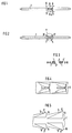
- 1 to 7 accordingly has two pairs of lugs 3 and 3 'at a first location at two mutually opposite locations and also at two at a closely adjacent second location opposite points - based on the circumference of the contact pin - lying in the same angular position - each two further pairs of noses 4 or 4 ', the two noses of a pair of noses 3, 3', 4 or 4 '- as is particularly clear from the enlarged view 4 can be seen - are impressed into the contact pin from above and below.
- the pairs of lugs have a contour which rises in the opposite direction to the direction in which the contact pin 1 is inserted, so that they protrude beyond the original circumference of the contact pin with nose flanks 5 inclined obliquely to the longitudinal axis of the contact pin and a steep retaining flank 6 transverse to the longitudinal axis of the contact pin.
- the rear lug pairs 4,4 'of the contact pin 1 have a greater height than the front lug pairs 3,3', so that the contact pin 1 in section BB has a somewhat larger cross section than section AA .
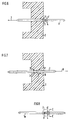
- a contact pin 1 is inserted into a receiving opening of a plastic part 2, for example into a pin strip, in a direction of insertion indicated by an arrow 7. In its end position shown in FIG. 7, the contact pin 1 is then securely anchored in the plastic part 2 in the event of forces occurring in the direction of an arrow 8 (direction of holding force) due to the barb-like pairs of lugs.
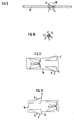
- the second embodiment of a contact pin 1 a shown in FIGS. 8 to 14 differs from the embodiment shown in FIGS. 1 to 7 only in the angular position of the pairs of noses 3, 3 'and 4, 4' in relation to the circumference of the contact pin. .
- the 7 rear pairs of noses 4,4 'in the direction of insertion are offset by 90 ° with respect to the front pairs of noses 3,3', the front and rear pairs of noses 3,3 'and 4,4' being able to have the same height. Otherwise it is Contour and the arrangement of the pairs of noses 3,3 'and 4,4' identical to the embodiment according to FIGS. 1 to 7.
Landscapes
- Connector Housings Or Holding Contact Members (AREA)
- Coupling Device And Connection With Printed Circuit (AREA)
Abstract
Description
Die Erfindung betrifft einen Kontaktstift für Steckverbindungen, der an seinem Umfang mit Einprägungen versehen und in eine Aufnahmeöffnung eines Kunststoffkörpers einschiebbar und darin klemmend befestigbar ist, wobei sich die Einprägungen in die Innenwand der Aufnahmeöffnung eindrücken.The invention relates to a contact pin for plug connections, which is provided with impressions on its periphery and can be inserted into a receiving opening of a plastic body and fastened therein by clamping, the impressions being pressed into the inner wall of the receiving opening.
Ein derartiger Kontaktstift ist durch die DE-OS 25 23 448 bekannt. Dieser Kontaktstift ist mit einem im Querschnitt quadratischen Halteschaft ausgebildet, in den umlaufende, schräg zur Längsachse des Stiftes geneigte und an den höchsten Stellen abgeflachte Querrippen eingeprägt sind.Such a contact pin is known from DE-OS 25 23 448. This contact pin is formed with a holding shaft with a square cross section, into which circumferential transverse ribs, which are inclined at an angle to the longitudinal axis of the pin and flattened at the highest points, are embossed.
Der Erfindung liegt die Aufgabe zugrunde, bei einem Kontaktstift der eingangs genannten Art in einem reproduzierbaren Fertigungsprozeß eine ausreichende Festsitzkraft zu erreichen und dabei möglichst hohe Haltekräfte zu gewährleisten.The invention has for its object to achieve a sufficient tightness with a contact pin of the type mentioned in a reproducible manufacturing process and to ensure the highest possible holding forces.
Diese Aufgabe wird bei einem Kontaktstift der eingangs genannten Art gemäß der Erfindung dadurch gelöst, daß die Einprägungen an zwei in Längsrichtung des Kontaktstiftes nahe hintereinanderliegenden Stellen vorgesehen und jeweils paarweise an zwei einander gegenüberliegenden Stellen am Umfang des Kontaktstiftes angebracht und als über den Umfang des Kontaktstiftes hinaus vorstehende Nasenpaare ausgeführt sind, und daß diese Nasenpaare jeweils eine zu der Einschieberichtung des Kontaktstiftes entgegengesetzt ansteigende Kontur aufweisen.
Ein derartiger Kontaktstift ist an zwei in Längsrichtung nahe benachbarten Stellen mit zweiseitig an seinem Umfang angeprägten Nasenpaaren, also mit insgesamt vier Nasenpaaren, ausgebildet, die in einfacher Weise in einem reproduzierbaren Fertigungsprozeß durch Prägestempel angebracht werden, welche Material des Kontaktstiftes über dessen ursprünglichen Umfang hinaus nach außen drucken. Dabei weisen die Nasenpaare eine zur Einschieberichtung des Kontaktstiftes entgegengesetzt ansteigende Kontur mit zur Längsachse des Kontaktstiftes schräg geneigten Nasenflanken und einer steilen Hinterflanke auf. Dadurch wird beim Einschieben des Kontaktstiftes in die Aufnahmeöffnung eines Kunststoffkörpers der Kunststoff elastisch verdrängt und nicht abgeschabt. Infolge des elastischen Verdrängens des Kunststoffes befindet sich in der Endposition des Kontaktstiftes ausreichend Kunststoffmaterial an der zur Längsachse des Kontaktstiftes quer verlaufenden steilen hinteren Halteflanke der Nasenpaare. Auf diese Weise ist die entgegengesetzt zur Einschieberichtung des Kontaktstiftes gerichtete Haltekraft ausreichend groß. Damit werden sichere Verankerungen von Kontaktstiften in Kunststoffteilen, z.B. in Stiftleisten von Steckverbindungen erreicht, die verhindern, daß die Kontaktstifte beim Aufstecken von Gegensteckern, wie z.B. Kontaktbuchsen, aus dem Kunststoffteil herausbewegt werden. Außerdem wird durch einen derartigen Festsitz eines Kontaktstiftes in der Aufnahmeöffnung eines Kunststoffteiles auch eine wirksame Dichtung der Aufnahmeöffnung gegen bei späteren Bearbeitungsvorgängen gegebenenfalls aufsteigende Mittel, wie z.B. Flußmittel bei Lötvorgängen oder Lackflüssigkeiten, erreicht.This object is achieved in a contact pin of the type mentioned in accordance with the invention in that the impressions are provided at two points located one behind the other in the longitudinal direction of the contact pin and are each attached in pairs at two opposite points on the circumference of the contact pin and as beyond the circumference of the contact pin protruding pairs of lugs are executed, and that these pairs of lugs each have a rising opposite to the direction of insertion of the contact pin contour.
A contact pin of this type is stamped at two adjacent points in the longitudinal direction with two sides stamped on its circumference Nose pairs, that is to say with a total of four pairs of noses, which are attached in a simple manner in a reproducible manufacturing process by means of stamping dies, which print the material of the contact pin beyond its original circumference to the outside. The pairs of lugs have a contour which rises in the opposite direction to the direction in which the contact pin is inserted, with nose flanks which are inclined at an angle to the longitudinal axis of the contact pin and a steep rear flank. As a result, when the contact pin is inserted into the receiving opening of a plastic body, the plastic is elastically displaced and is not scraped off. As a result of the elastic displacement of the plastic, there is sufficient plastic material in the end position of the contact pin on the steep rear retaining flank of the pairs of noses which runs transversely to the longitudinal axis of the contact pin. In this way, the holding force directed opposite to the direction of insertion of the contact pin is sufficiently large. In this way, secure anchoring of contact pins in plastic parts, for example in pin strips of plug connections, is achieved which prevent the contact pins from being moved out of the plastic part when mating connectors, such as contact sockets, are plugged on. In addition, such a tight fit of a contact pin in the receiving opening of a plastic part also provides an effective sealing of the receiving opening against agents which may rise during later processing operations, such as, for example, flux during soldering processes or paint liquids.
Bei einem ersten Ausführungsbeispiel eines erfindungsgemäßen Kontaktstiftes weisen die in Einschieberichtung hinteren Nasenpaare gegenüber den vorderen Nasenpaaren eine größere Höhe auf. Durch diese Maßnahme wird der sichere Sitz eines Kontaktstiftes in der Aufnahmeöffnung eines Kunststoffteiles zusätzlich verbessert.In a first embodiment of a contact pin according to the invention, the rear nose pairs in the insertion direction have a greater height than the front nose pairs. This measure ensures the secure fit of one Contact pin in the receiving opening of a plastic part additionally improved.
Dieser Vorteil kann bei einem zweiten Ausführungsbeispiel eines erfindungsgemäßen Kontaktstiftes auch dadurch erreicht werden, daß die Nasenpaare an der einen Stelle des Kontaktstiftes um 90° gegenüber den Nasenpaaren an der anderen Stelle des Kontaktstiftes versetzt am Umfang des Kontaktstiftes angebracht sind.This advantage can also be achieved in a second exemplary embodiment of a contact pin according to the invention in that the pairs of noses at one point of the contact pin are offset by 90 ° relative to the nose pairs at the other point of the contact pin on the circumference of the contact pin.
Die Erfindung ist im folgenden anhand zweier in der Zeichnung dargestellter Ausführungsbeispiele eines Kontaktstiftes näher erläutert. Es zeigen
- Fig. 1 eine erste Ausführungsform eines Kontaktstiftes in Seitenansicht,
- Fig. 2 den Kontaktstift nach Fig. 1 in Draufsicht,
- Fig. 3 den Kontaktstift im Schnitt A-A und B-B nach Fig.1,
- Fig. 4 eine Einzelheit X des Kontaktstiftes nach Fig. 1 in vergrößerter Darstellung,
- Fig. 5 eine Einzelheit Y des Kontaktstiftes nach Fig.2 in vergrößerter Darstellung,
- Fig. 6 einen Teilbereich eines im Schnitt dargestellten Kunststoffteiles mit einem in eine Aufnahmeöffnung einschiebbaren Kontaktstift,
- Fig. 7 das Kunststoffteil nach Fig.6 mit einem in seine Endposition eingeschobenen Kontaktstift,
- Fig. 8 eine zweite Ausführungsform eines Kontaktstiftes in Seitenansicht,
- Fig. 9 den Kontaktstift nach Fig. 8 in Draufsicht,
- Fig. 10 den Kontaktstift im Schnitt C-C nach Fig. 8,
- Fig. 11 eine Einzelheit Z des Kontaktstiftes nach Fig.8 in vergrößerter Darstellung,
- Fig. 12 eine Einzelheit W des Kontaktstiftes nach Fig.9 in vergrößerter Darstellung,
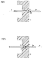
- Fig. 13 einen Teilbereich eines im Schnitt dargestellten Kunststoffteiles mit einem in eine Aufnahmeöffnung einschiebbaren Kontaktstift und
- Fig. 14 das Kunststoffteil nach Fig.13 mit einem in seine Endposition eingeschobenen Kontaktstift.
- 1 shows a first embodiment of a contact pin in side view,
- 2 is a top view of the contact pin according to FIG. 1,
- 3 shows the contact pin in section AA and BB according to FIG. 1,
- 4 shows a detail X of the contact pin according to FIG. 1 in an enlarged view,
- 5 shows a detail Y of the contact pin according to Figure 2 in an enlarged view,
- 6 shows a partial area of a plastic part shown in section with a contact pin that can be inserted into a receiving opening,
- 7 shows the plastic part according to FIG. 6 with a contact pin pushed into its end position,
- 8 shows a second embodiment of a contact pin in side view,
- 9 is a top view of the contact pin according to FIG. 8,
- 10 shows the contact pin in section CC according to FIG. 8,
- 11 shows a detail Z of the contact pin according to FIG. 8 in an enlarged view,
- 12 shows a detail W of the contact pin according to FIG. 9 in an enlarged view,
- 13 shows a partial area of a plastic part shown in section with a contact pin which can be inserted into a receiving opening and
- 14 the plastic part according to FIG. 13 with a contact pin pushed into its end position.
Der Kontaktstift hat beispielsweise eine quadratische Querschnittsform mit einer Kantenlänge von z.B. 0,6 mm und ist an seinem Umfang an zwei in Längsrichtung des Kontaktstiftes nahe hintereinander liegenden Stellen mit Einprägungen versehen. Diese sind bei beiden Ausführungsformen jeweils paarweise an zwei einander gegenüberliegenden Stellen am Umfang des Kontaktstiftes angebracht und als über den Umfang des Kontaktstiftes hinaus vorstehende Nasenpaare ausgeführt, wobei diese Nasenpaare jeweils eine zu der Einschieberichtung des Kontaktstiftes entgegengesetzt ansteigende Kontur aufweisen. Der in den Fig.1 bis 7 dargestellte Kontaktstift 1 weist demnach an einer ersten Stelle an zwei einander gegenüberliegenden Stellen jeweils zwei Nasenpaare 3 bzw. 3' und an einer nahe benachbarten zweiten Stelle ebenfalls an zwei einander gegenüberliegenden Stellen - bezogen auf den Umfang des Kontaktstiftes - in derselben Winkellage liegend - jeweils zwei weitere Nasenpaare 4 bzw. 4' auf, wobei die beiden Nasen eines Nasenpaares 3,3', 4 oder 4' - wie besonders deutlich aus der vergrößerten Darstellung in Fig. 4 erkennbar wird - von oben und unten in den Kontaktstift eingeprägt sind. Die Nasenpaare haben eine zu der Einschieberichtung des Kontaktstiftes 1 entgegengesetzt ansteigende Kontur, so daß sie mit schräg zur Längsachse des Kontaktstiftes geneigten Nasenflanken 5 und einer quer zur Längsachse des Kontaktstiftes hinteren steilen Halteflanke 6 über den ursprünglichen Umfang des Kontaktstiftes hinausragen. Wie vor allem die Fig. 5 zeigt, weisen die hinteren Nasenpaare 4,4' des Kontaktstiftes 1 eine größere Höhe auf als die vorderen Nasenpaare 3,3', so daß der Kontaktstift 1 im Schnitt B-B einen gegenüber dem Schnitt A-A etwas größeren Querschnitt hat. In Fig. 6 wird ein Kontaktstift 1 in eine Aufnahmeöffnung eines Kunststoffteiles 2, z.B. in eine Stiftleiste, eingeschoben, und zwar in einer durch einen Pfeil 7 gekennzeichneten Einschieberichtung. In seiner in Fig.7 dargestellten Endposition ist der Kontaktstift 1 dann bei in Richtung eines Pfeiles 8 auftretenden Kräften (Haltekraftrichtung) aufgrund der widerhakenartig wirkenden Nasenpaare sicher im Kunststoffteil 2 verankert.The contact pin has, for example, a square cross-sectional shape with an edge length of, for example, 0.6 mm and is provided with embossments on its circumference at two points lying one behind the other in the longitudinal direction of the contact pin. In both embodiments, these are each attached in pairs at two mutually opposite locations on the circumference of the contact pin and are designed as pairs of noses projecting beyond the circumference of the contact pin, these pairs of noses each having a contour that increases in the opposite direction to the direction in which the contact pin is inserted. The contact pin 1 shown in FIGS. 1 to 7 accordingly has two pairs of
Die in den Fig. 8 bis 14 dargestellte zweite Ausführungsform eines Kontaktstiftes 1a unterscheidet sich von der in den Fig. 1 bis 7 dargestellten Ausführungsform lediglich durch die auf den Umfang des Kontaktstiftes bezogene Winkellage der hintereinander liegenden Nasenpaare 3,3' und 4,4'. Hierbei sind die in Einschieberichtung 7 hinteren Nasenpaare 4,4' um 90° gegenüber den vorderen Nasenpaaren 3,3' versetzt, wobei die vorderen und hinteren Nasenpaare 3,3'und 4,4' die gleiche Höhe aufweisen können. Ansonsten ist die Kontur und die Anordnung der Nasenpaare 3,3' und 4,4' mit der Ausführung nach den Fig. 1 bis 7 identisch.The second embodiment of a contact pin 1 a shown in FIGS. 8 to 14 differs from the embodiment shown in FIGS. 1 to 7 only in the angular position of the pairs of
Claims (3)
dadurch gekennzeichnet, daß die Einprägungen an zwei in Längsrichtung des Kontaktstiftes (1,1a) nahe hintereinanderliegenden Stellen vorgesehen und jeweils paarweise an zwei einander gegenüberliegenden Stellen am Umfang des Kontaktstiftes angebracht und als über den Umfang des Kontaktstiftes hinaus vorstehende Nasenpaare (3,3'bzw. 4,4') ausgeführt sind, und daß diese Nasenpaare jeweils eine zu der Einschieberichtung des Kontaktstiftes entgegengesetzt ansteigende Kontur aufweisen.Contact pin for plug connections, which is provided with impressions on its circumference and can be inserted into a receiving opening of a plastic body and fastened in a clamping manner, the impressions pressing into the inner wall of the receiving opening,
characterized in that the embossments are provided at two points located one behind the other in the longitudinal direction of the contact pin (1,1a) and are each attached in pairs at two opposite points on the circumference of the contact pin and as pairs of noses (3, 3 'or 3') projecting beyond the circumference of the contact pin . 4,4 ') and that these pairs of lugs each have a contour that rises in the opposite direction to the direction in which the contact pin is inserted.
dadurch gekennzeichnet, daß die in Einchieberichtung hinteren Nasenpaare (4,4') gegenüber den vorderen Nasenpaaren (3,3') eine größere Höhe aufweisen.Contact pin according to claim 1,
characterized in that the rear nose pairs (4,4 ') in the direction of insertion have a greater height than the front nose pairs (3,3').
dadurch gekennzeichnet, daß die Nasenpaare (4,4') an der einen Stelle des Kontaktstiftes (1a) um 90° gegenüber den Nasenpaaren (3,3') an der anderen Stelle des Kontaktstiftes versetzt am Umfang des Kontaktstiftes angebracht sind.Contact pin according to claim 1 or 2,
characterized in that the lug pairs (4,4 ') at one point of the contact pin (1a) are offset by 90 ° with respect to the lug pairs (3,3') at the other point of the contact pin on the circumference of the contact pin.
Applications Claiming Priority (2)
| Application Number | Priority Date | Filing Date | Title |
|---|---|---|---|
| DE9314676U | 1993-09-28 | ||
| DE9314676U DE9314676U1 (en) | 1993-09-28 | 1993-09-28 | Contact pin for plug connections |
Publications (2)
| Publication Number | Publication Date |
|---|---|
| EP0647986A1 true EP0647986A1 (en) | 1995-04-12 |
| EP0647986B1 EP0647986B1 (en) | 1996-11-27 |
Family
ID=6898670
Family Applications (1)
| Application Number | Title | Priority Date | Filing Date |
|---|---|---|---|
| EP94114228A Expired - Lifetime EP0647986B1 (en) | 1993-09-28 | 1994-09-09 | Contact pin for plug connections |
Country Status (3)
| Country | Link |
|---|---|
| EP (1) | EP0647986B1 (en) |
| DE (2) | DE9314676U1 (en) |
| ES (1) | ES2094607T3 (en) |
Cited By (4)
| Publication number | Priority date | Publication date | Assignee | Title |
|---|---|---|---|---|
| US5692928A (en) * | 1996-05-10 | 1997-12-02 | Molex Incorporated | Electrical connector having terminals with improved retention means |
| EP0854542A2 (en) * | 1997-01-13 | 1998-07-22 | Framatome Connectors International | Contact pin having anchoring wings in opposite directions, and connector element |
| US5807142A (en) * | 1996-05-10 | 1998-09-15 | Molex Incorporated | Electrical connector having terminals with improved retention means |
| WO2018215385A1 (en) * | 2017-05-23 | 2018-11-29 | Te Connectivity Germany Gmbh | Contact pin |
Citations (3)
| Publication number | Priority date | Publication date | Assignee | Title |
|---|---|---|---|---|
| GB1087422A (en) * | 1964-02-27 | 1967-10-18 | Malco Mfg Company Inc | Electrical terminal |
| US5035656A (en) * | 1990-05-15 | 1991-07-30 | E. I. Du Pont De Nemours And Company | Connector, circuit board contact element and retention portion |
| US5147227A (en) * | 1991-10-17 | 1992-09-15 | Amp Incorporated | Terminal retention device |
-
1993
- 1993-09-28 DE DE9314676U patent/DE9314676U1/en not_active Expired - Lifetime
-
1994
- 1994-09-09 EP EP94114228A patent/EP0647986B1/en not_active Expired - Lifetime
- 1994-09-09 ES ES94114228T patent/ES2094607T3/en not_active Expired - Lifetime
- 1994-09-09 DE DE59401150T patent/DE59401150D1/en not_active Expired - Lifetime
Patent Citations (3)
| Publication number | Priority date | Publication date | Assignee | Title |
|---|---|---|---|---|
| GB1087422A (en) * | 1964-02-27 | 1967-10-18 | Malco Mfg Company Inc | Electrical terminal |
| US5035656A (en) * | 1990-05-15 | 1991-07-30 | E. I. Du Pont De Nemours And Company | Connector, circuit board contact element and retention portion |
| US5147227A (en) * | 1991-10-17 | 1992-09-15 | Amp Incorporated | Terminal retention device |
Cited By (8)
| Publication number | Priority date | Publication date | Assignee | Title |
|---|---|---|---|---|
| US5692928A (en) * | 1996-05-10 | 1997-12-02 | Molex Incorporated | Electrical connector having terminals with improved retention means |
| US5807142A (en) * | 1996-05-10 | 1998-09-15 | Molex Incorporated | Electrical connector having terminals with improved retention means |
| EP0854542A2 (en) * | 1997-01-13 | 1998-07-22 | Framatome Connectors International | Contact pin having anchoring wings in opposite directions, and connector element |
| EP0854542A3 (en) * | 1997-01-13 | 1999-10-13 | Framatome Connectors International | Contact pin having anchoring wings in opposite directions, and connector element |
| WO2018215385A1 (en) * | 2017-05-23 | 2018-11-29 | Te Connectivity Germany Gmbh | Contact pin |
| CN110651397A (en) * | 2017-05-23 | 2020-01-03 | 泰连德国有限公司 | Contact pin |
| US11069996B2 (en) | 2017-05-23 | 2021-07-20 | Te Connectivity Germany Gmbh | Contact pin for plug connector having retaining elements |
| CN110651397B (en) * | 2017-05-23 | 2021-08-10 | 泰连德国有限公司 | Contact pin |
Also Published As
| Publication number | Publication date |
|---|---|
| DE9314676U1 (en) | 1994-02-24 |
| DE59401150D1 (en) | 1997-01-09 |
| ES2094607T3 (en) | 1997-01-16 |
| EP0647986B1 (en) | 1996-11-27 |
Similar Documents
| Publication | Publication Date | Title |
|---|---|---|
| DE68922376T2 (en) | TOLERANCE ACCEPTING PLATE FASTENING. | |
| DE4040748C2 (en) | ||
| DE69306463T2 (en) | Electrical flat connector | |
| DE2409075A1 (en) | ELECTRIC CONNECTOR | |
| EP3488128B1 (en) | Seal element for connecting a first component and a second component in a fluid-tight and electrically conductive manner, and corresponding component assembly | |
| DE19848289C2 (en) | Locking device of a cap part | |
| WO2021151426A1 (en) | Add-on housing | |
| EP0647986B1 (en) | Contact pin for plug connections | |
| DE4205974C1 (en) | Electrical plug connector with built-in latching for pins - provides section formed on housing that locates against pin flange and is held by latch stage | |
| DE69901151T2 (en) | Electrical and / or optical connector | |
| DE102016220022B4 (en) | Combination of a plug with a cover | |
| DE4301602C1 (en) | Electrical connector part with synthetic housing - has guide rails leading from entry opening of admission chamber to plug-in opening for mating contact element | |
| EP0703641A2 (en) | Electrical connection member | |
| EP0691711B1 (en) | Connector | |
| DE10248119B3 (en) | Plug-in card for electronic data processing devices | |
| EP0415136A1 (en) | Connector insert for a metallic housing | |
| DE60102546T2 (en) | Electrical connector | |
| DE19639665A1 (en) | Movable connector with support plate extension | |
| DE19720196C2 (en) | Measuring mechanism | |
| DE60004607T2 (en) | Enclosure for panel mount bushing type electrical connector | |
| CH660934A5 (en) | Screening casing and an electrical plug assembly equipped therewith, especially an apparatus plug with an interference-protection filter | |
| DE3210936C2 (en) | Connector | |
| DE10140243C1 (en) | Coupling device for electrical connector elements used in automobile uses coupling cap securing connector element on one side of plate with connector element on opposite side of plate | |
| DE10029222A1 (en) | Electric installation unit for mounting opening in installation box, has carrying ring and socket in which ring includes ring plate and feet vertically projecting from plate | |
| DE102019106093B4 (en) | Holding frame and connector with such a holding frame |
Legal Events
| Date | Code | Title | Description |
|---|---|---|---|
| PUAI | Public reference made under article 153(3) epc to a published international application that has entered the european phase |
Free format text: ORIGINAL CODE: 0009012 |
|
| AK | Designated contracting states |
Kind code of ref document: A1 Designated state(s): BE DE ES FR GB IT SE |
|
| 17P | Request for examination filed |
Effective date: 19950504 |
|
| 17Q | First examination report despatched |
Effective date: 19951025 |
|
| GRAG | Despatch of communication of intention to grant |
Free format text: ORIGINAL CODE: EPIDOS AGRA |
|
| GRAH | Despatch of communication of intention to grant a patent |
Free format text: ORIGINAL CODE: EPIDOS IGRA |
|
| GRAH | Despatch of communication of intention to grant a patent |
Free format text: ORIGINAL CODE: EPIDOS IGRA |
|
| GRAA | (expected) grant |
Free format text: ORIGINAL CODE: 0009210 |
|
| AK | Designated contracting states |
Kind code of ref document: B1 Designated state(s): BE DE ES FR GB IT SE |
|
| REF | Corresponds to: |
Ref document number: 59401150 Country of ref document: DE Date of ref document: 19970109 |
|
| REG | Reference to a national code |
Ref country code: ES Ref legal event code: FG2A Ref document number: 2094607 Country of ref document: ES Kind code of ref document: T3 |
|
| ET | Fr: translation filed | ||
| ITF | It: translation for a ep patent filed | ||
| GBT | Gb: translation of ep patent filed (gb section 77(6)(a)/1977) |
Effective date: 19970130 |
|
| PLBE | No opposition filed within time limit |
Free format text: ORIGINAL CODE: 0009261 |
|
| STAA | Information on the status of an ep patent application or granted ep patent |
Free format text: STATUS: NO OPPOSITION FILED WITHIN TIME LIMIT |
|
| 26N | No opposition filed | ||
| PGFP | Annual fee paid to national office [announced via postgrant information from national office to epo] |
Ref country code: SE Payment date: 20000901 Year of fee payment: 7 |
|
| PGFP | Annual fee paid to national office [announced via postgrant information from national office to epo] |
Ref country code: ES Payment date: 20000926 Year of fee payment: 7 |
|
| PGFP | Annual fee paid to national office [announced via postgrant information from national office to epo] |
Ref country code: BE Payment date: 20001010 Year of fee payment: 7 |
|
| REG | Reference to a national code |
Ref country code: GB Ref legal event code: 732E |
|
| PG25 | Lapsed in a contracting state [announced via postgrant information from national office to epo] |
Ref country code: SE Free format text: LAPSE BECAUSE OF NON-PAYMENT OF DUE FEES Effective date: 20010910 Ref country code: ES Free format text: LAPSE BECAUSE OF NON-PAYMENT OF DUE FEES Effective date: 20010910 |
|
| PG25 | Lapsed in a contracting state [announced via postgrant information from national office to epo] |
Ref country code: BE Free format text: LAPSE BECAUSE OF NON-PAYMENT OF DUE FEES Effective date: 20010930 |
|
| REG | Reference to a national code |
Ref country code: GB Ref legal event code: IF02 |
|
| BERE | Be: lapsed |
Owner name: SIEMENS A.G. Effective date: 20010930 |
|
| EUG | Se: european patent has lapsed |
Ref document number: 94114228.3 |
|
| PGFP | Annual fee paid to national office [announced via postgrant information from national office to epo] |
Ref country code: GB Payment date: 20020808 Year of fee payment: 9 |
|
| PGFP | Annual fee paid to national office [announced via postgrant information from national office to epo] |
Ref country code: FR Payment date: 20020903 Year of fee payment: 9 |
|
| PG25 | Lapsed in a contracting state [announced via postgrant information from national office to epo] |
Ref country code: GB Free format text: LAPSE BECAUSE OF NON-PAYMENT OF DUE FEES Effective date: 20030909 |
|
| GBPC | Gb: european patent ceased through non-payment of renewal fee |
Effective date: 20030909 |
|
| REG | Reference to a national code |
Ref country code: ES Ref legal event code: FD2A Effective date: 20021011 |
|
| PG25 | Lapsed in a contracting state [announced via postgrant information from national office to epo] |
Ref country code: FR Free format text: LAPSE BECAUSE OF NON-PAYMENT OF DUE FEES Effective date: 20040528 |
|
| REG | Reference to a national code |
Ref country code: FR Ref legal event code: ST |
|
| PG25 | Lapsed in a contracting state [announced via postgrant information from national office to epo] |
Ref country code: IT Free format text: LAPSE BECAUSE OF NON-PAYMENT OF DUE FEES;WARNING: LAPSES OF ITALIAN PATENTS WITH EFFECTIVE DATE BEFORE 2007 MAY HAVE OCCURRED AT ANY TIME BEFORE 2007. THE CORRECT EFFECTIVE DATE MAY BE DIFFERENT FROM THE ONE RECORDED. Effective date: 20050909 |
|
| PGFP | Annual fee paid to national office [announced via postgrant information from national office to epo] |
Ref country code: DE Payment date: 20130927 Year of fee payment: 20 |
|
| REG | Reference to a national code |
Ref country code: DE Ref legal event code: R071 Ref document number: 59401150 Country of ref document: DE |
|
| PG25 | Lapsed in a contracting state [announced via postgrant information from national office to epo] |
Ref country code: DE Free format text: LAPSE BECAUSE OF EXPIRATION OF PROTECTION Effective date: 20140910 |