EP0415136A1 - Connector insert for a metallic housing - Google Patents
Connector insert for a metallic housing Download PDFInfo
- Publication number
- EP0415136A1 EP0415136A1 EP90115124A EP90115124A EP0415136A1 EP 0415136 A1 EP0415136 A1 EP 0415136A1 EP 90115124 A EP90115124 A EP 90115124A EP 90115124 A EP90115124 A EP 90115124A EP 0415136 A1 EP0415136 A1 EP 0415136A1
- Authority
- EP
- European Patent Office
- Prior art keywords
- contact carrier
- protective sleeve
- collar
- plug insert
- protective
- Prior art date
- Legal status (The legal status is an assumption and is not a legal conclusion. Google has not performed a legal analysis and makes no representation as to the accuracy of the status listed.)
- Granted
Links
Images
Classifications
-
- H—ELECTRICITY
- H01—ELECTRIC ELEMENTS
- H01R—ELECTRICALLY-CONDUCTIVE CONNECTIONS; STRUCTURAL ASSOCIATIONS OF A PLURALITY OF MUTUALLY-INSULATED ELECTRICAL CONNECTING ELEMENTS; COUPLING DEVICES; CURRENT COLLECTORS
- H01R13/00—Details of coupling devices of the kinds covered by groups H01R12/70 or H01R24/00 - H01R33/00
- H01R13/46—Bases; Cases
- H01R13/502—Bases; Cases composed of different pieces
-
- Y—GENERAL TAGGING OF NEW TECHNOLOGICAL DEVELOPMENTS; GENERAL TAGGING OF CROSS-SECTIONAL TECHNOLOGIES SPANNING OVER SEVERAL SECTIONS OF THE IPC; TECHNICAL SUBJECTS COVERED BY FORMER USPC CROSS-REFERENCE ART COLLECTIONS [XRACs] AND DIGESTS
- Y10—TECHNICAL SUBJECTS COVERED BY FORMER USPC
- Y10S—TECHNICAL SUBJECTS COVERED BY FORMER USPC CROSS-REFERENCE ART COLLECTIONS [XRACs] AND DIGESTS
- Y10S439/00—Electrical connectors
- Y10S439/901—Connector hood or shell
- Y10S439/903—Special latch for insert
Definitions
- the invention relates to a plug insert for a metal tube housing, comprising a contact carrier, from which plug pins protrude from a first side and solder connections from a first opposite second side, a protective sleeve which can be inserted into the metal tube and surrounds the contact carrier and which extends from the first side of the contact carrier extends in a first direction parallel to the connector pins with its front side and in a second direction, opposite to the first, forms a protective collar projecting beyond the second side of the contact carrier.
- the contact carrier is formed in one piece with the protective sleeve and the protective collar extends in the second direction by the same distance as the solder connections in order to make it possible to solder cables to these solder connections.
- Such plug inserts are provided in particular for metal tube housings with an inner diameter of less than 12 mm, so that due to the limited space in the plug insert according to the prior art, the protective collar may only extend to the end of the solder connections in order to solder cables to these solder connections still allow.
- the invention is therefore based on the object of improving a plug insert of the generic type, in particular for metal tube housings with small diameters, preferably for metal tube housings with an inner diameter of 12 mm or less, in such a way that this also for high insulation voltages, in particular insulation voltages of 250 V and more, can be used.
- the protective sleeve extends in the first direction at least to one end of the connector pins. It is even better if it extends beyond this.
- the protective collar can in principle protrude as far beyond the solder connections.
- a solution is particularly preferred in which the protective collar projects beyond the solder connections by at least 5 mm.
- the contact carrier can be insertable into the protective sleeve from both sides.
- the contact carrier can be inserted into the protective sleeve from the front side.
- the contact carrier has an annular recess facing the protective sleeve and open towards the second side.
- the contact carrier can be fixed in a particularly defined manner if the collar has a conical seat. It is accordingly also advantageous if the recess has a conical ring wall corresponding to the seat.
- solder connections on the contact carrier it has proven to be particularly advantageous if, starting from the second side of the contact carrier, the solder connections are freely accessible in the second direction and perpendicular to it.
- the contact carrier is preferably designed in such a way that it extends in the second direction to a surface defined by the second side, that is to say does not have any areas that project beyond the second side.
- the protective collar 52 completely lines the metal tube housing over its entire extent in the second direction.
- the protective sleeve and the contact carrier are made of a non-conductive material, preferably of plastic.
- An exemplary embodiment of a plug insert according to the invention for a cylindrical metal tube housing 10 comprises a cylindrical protective sleeve 14 which can be inserted into this from a front end 12 of the metal tube housing 10 and which has a front collar 18 which is in the inserted state and rests on an end face 16 arranged at the front end 12.
- This collar 18 is preferably provided with an outer diameter identical to the metal tube housing 10. This collar 18 defines the position of the protective sleeve 14 in the inserted state shown in FIG. 1.
- the protective sleeve 14 is shaped in the manner of a cylinder jacket and has a cylindrical inner wall surface 20.
- a contact carrier designated as a whole with 22 can be inserted from the side of the collar 18, which comprises a contact carrier plate 24 which, when inserted into the protective sleeve 14, has a first side 26 facing the collar 16 and a second side facing away from the collar 16 Page 28. Furthermore, on the first side 26 of the contact carrier plate 24, a cylindrical projection 30 protrudes in the direction of the collar 18, which is integrally formed on the contact carrier plate 24 and together with it forms a cylindrical outer surface 32 with which the contact carrier 22 on the inner wall surface 20 of the Protective sleeve 14 is guided.
- the protective sleeve 14 has an annular collar 33 projecting inwards from the inner wall surface 20, which on its side facing the collar 18 has an annular surface 34 which slopes conically in the direction of the inner wall surface 20 and additionally an inner surface parallel to the inner wall surface 20 36.
- the contact carrier plate 24 is shaped accordingly. It has an adjoining the cylindrical outer surface 32, a conically extending radially inward ring surface which can be brought into contact with the annular surface 34, and an adjoining the annular surface 38 and on the inner surface 36, the outer surface 40 holding the contact carrier plate 24 centered.
- the contact carrier 22 can thus be inserted into the protective sleeve 14 from the collar 16 until the annular surface 34 and the annular surface 38 come into contact with one another.
- the position of the contact carrier 22 is determined by plug pins 42 which extend from the first side 26 away from the contact carrier plate 24 and which should extend to the collar 18 and preferably end directly in front of a front side 44 of the protective sleeve 14.
- the connector pins 42 extend parallel to a longitudinal axis 46 of the metal tube housing 10 and the protective sleeve 14 in a first direction 45, while the solder connections 48 extend opposite to the first direction 45 in a second direction 47 parallel to the longitudinal axis.
- a protective collar 52 covering the entire inner wall surface 20 also extends in this direction.
- connection 48 assigned to the plug pins 42, to which connection cables 50 leading inside the metal tube housing and only shown in broken lines can be soldered.
- the protective collar 52 is formed by the section 52 of the protective sleeve 14 which extends in the second direction 47 from the second side 28 and is intended to prevent flashovers from the solder connections 48 to the metal tube housing 10, the protective collar 52 an air gap L leading from a rear end 54 of the solder connections 48 to the metal tube housing 10 is to be kept as large as possible.
- the air gap L is more than 5 mm.
- the protective collar 52 thus extends at least 5 mm from the rear end 54 of the solder connections 48 away from the second side 28 in the direction of the longitudinal axis 46.
- the plug insert according to the invention is now assembled by first soldering the cables 50 to the solder connections 48 when the contact carrier 22 is not inserted into the protective sleeve 14, and then inserting the contact carrier 22 from the collar 18 into the protective sleeve 14 and on the collar 32 is preferably fixed by press fitting, as shown in Fig. 1.
- a snap-in connection can be provided, for which purpose the contact carrier plate is preferably provided at the level of the second side 28 with radially outwardly projecting claws 60, which engage in corresponding recesses 62 in the inner surface 36 of the annular collar 32 and thus prevent the contact carrier plate 24 from moving in the direction of the collar 18.
- the contact carrier 22 is welded to the protective sleeve 14 in the contact area of the Inner wall surface 20 facing outer surface 32 of the cylindrical projection 30 with the inner wall surface 20 of the protective sleeve 14, wherein a weld 66 is formed, which preferably runs around the inner wall surface 20.
- the protective sleeve 14 is made of a translucent or transparent material.
Landscapes
- Connector Housings Or Holding Contact Members (AREA)
- Coupling Device And Connection With Printed Circuit (AREA)
Abstract
Um einen Steckereinsatz für ein Metallrohrgehäuse, umfassend einen Kontaktträger, von welchem Steckerstifte von einer ersten Seite und Lötanschlüsse von einer der ersten gegenüberliegenden zweiten Seite abstehen, eine den Kontaktträger umgebende, in das Metallrohr einführbare Schutzhülse, welche sich von der ersten Seite des Kontaktträgers in einer ersten, zu den Steckerstiften parallelen Richtung mit ihrer vorderen Seite erstreckt und in einer zweiten Richtung, entgegengesetzt zur ersten, einen über die zweite Seite des Kontaktträgers überstehenden Schutzkragen bildet, derart zu verbessern, daß dieser auch für hohe Isolationsspannungen, insbesondere Isolationsspannungen von 250 V und mehr, einsetzbar ist, wird vorgeschlagen, daß die Schutzhülse und der Kontaktträger zwei zusammensetzbare Teile sind, daß die Schutzhülse eine Aufnahme aufweist, in welche der Kontaktträger einsetzbar und fixierbar ist, und daß bei in die Schutzhülse eingesetztem Kontaktträger der Schutzkragen in der zweiten Richtung über die Lötanschlüsse übersteht.Around a plug insert for a metal tube housing, comprising a contact carrier, from which plug pins protrude from a first side and solder connections from a first opposite second side, a protective sleeve surrounding the contact carrier and insertable into the metal tube, which extends from the first side of the contact carrier in a First, parallel to the connector pins extends with its front side and in a second direction, opposite to the first, a protruding over the second side of the contact carrier protective collar, to improve such that this also for high insulation voltages, in particular insulation voltages of 250 V and More, can be used, it is proposed that the protective sleeve and the contact carrier are two parts that can be assembled, that the protective sleeve has a receptacle in which the contact carrier can be inserted and fixed, and that when the contact carrier is inserted into the protective sleeve, the Protective collar protrudes in the second direction over the solder connections.
Description
Die Erfindung betrifft einen Steckereinsatz für ein Metallrohrgehäuse, umfassend einen Kontaktträger, von welchem Steckerstifte von einer ersten Seite und Lötanschlüsse von einer der ersten gegenüberliegenden zweiten Seite abstehen, eine den Kontaktträger umgebende in das Metallrohr einführbare Schutzhülse, welche sich von der ersten Seite des Kontaktträgers in einer ersten, zu den Steckerstiften parallelen Richtung mit ihrer vorderen Seite erstreckt und in einer zweiten Richtung, entgegengesetzt zur ersten, einen über die zweite Seite des Kontaktträgers überstehenden Schutzkragen bildet.The invention relates to a plug insert for a metal tube housing, comprising a contact carrier, from which plug pins protrude from a first side and solder connections from a first opposite second side, a protective sleeve which can be inserted into the metal tube and surrounds the contact carrier and which extends from the first side of the contact carrier extends in a first direction parallel to the connector pins with its front side and in a second direction, opposite to the first, forms a protective collar projecting beyond the second side of the contact carrier.
Ein derartiger Steckereinsatz ist aus dem Stand der Technik bekannt. Bei diesem ist der Kontaktträger einstückig mit der Schutzhülse ausgebildet und der Schutzkragen erstreckt sich in der zweiten Richtung um dieselbe Strecke wie die Lötanschlüsse, um ein Anlöten von Kabel an diese Lötanschlüsse noch möglich zu machen.Such a plug insert is known from the prior art. In this case, the contact carrier is formed in one piece with the protective sleeve and the protective collar extends in the second direction by the same distance as the solder connections in order to make it possible to solder cables to these solder connections.
Derartige Steckereinsätze sind insbesondere für Metallrohrgehäuse mit einem Innendurchmesser von weniger als 12 mm vorgesehen, so daß aufgrund der räumlichen Beengtheit bei dem Steckereinsatz gemäß dem Stand der Technik sich der Schutzkragen lediglich bis zum Ende der Lötanschlüsse erstrecken darf, um ein Anlöten von Kabeln an diese Lötanschlüsse noch zu ermöglichen.Such plug inserts are provided in particular for metal tube housings with an inner diameter of less than 12 mm, so that due to the limited space in the plug insert according to the prior art, the protective collar may only extend to the end of the solder connections in order to solder cables to these solder connections still allow.
Diese Steckereinsätze haben somit den Nachteil, daß sie aufgrund der räumlichen Beengtheit lediglich für Kleinspannungen verwendbar sind, da die für höhere Spannungen erforderliche Luftstrecke vom Lötanschluß bis zum Metallrohrgehäuse nicht erreichbar ist.These plug inserts therefore have the disadvantage that they can only be used for low voltages due to the limited space, since the air gap required for higher voltages from the solder connection to the metal tube housing cannot be reached.
Der Erfindung liegt daher die Aufgabe zugrunde, einen Steckereinsatz der gattungsgemäßen Art, insbesondere für Metallrohrgehäuse mit kleinen Durchmessern, vorzugsweise für Metallrohrgehäuse mit einem Innendurchmesser von 12 mm oder weniger, derart zu verbessern, daß dieser auch für hohe Isolationsspannungen, insbesondere Isolationsspannungen von 250 V und mehr, einsetzbar ist.The invention is therefore based on the object of improving a plug insert of the generic type, in particular for metal tube housings with small diameters, preferably for metal tube housings with an inner diameter of 12 mm or less, in such a way that this also for high insulation voltages, in particular insulation voltages of 250 V and more, can be used.
Diese Aufgabe wird bei einem Steckereinsatz der eingangs beschriebenen Art erfindungsgemäß dadurch gelöst, daß die Schutzhülse und der Kontaktträger zwei zusammensetzbare Teile sind, daß die Schutzhülse eine Aufnahme aufweist, in welche der Kontaktträger einsetzbar und fixierbar ist und daß bei in die Schutzhülse eingesetztem Kontaktträger der Schutzkragen in der zweiten Richtung über die Lötanschlüsse übersteht.This object is achieved according to the invention in a plug insert of the type described above in that the protective sleeve and the contact carrier are two parts which can be assembled, that the protective sleeve has a receptacle in which the contact carrier can be inserted and fixed, and that the protective collar is inserted into the protective sleeve when the contact carrier is inserted protrudes in the second direction over the solder connections.
Der Vorteil der erfindungsgemäßen Lösung ist insbesondere darin zu sehen, daß trotz eines über die Lötanschlüsse in der zweiten Richtung weit überstehenden Schutzkragens noch die Möglichkeit besteht, ein Kabel in einfacher Art und Weise mit den Lötanschlüssen zu verlöten, da dies erfolgen kann bevor der Kontaktträger in die Schutzhülse eingesetzt ist.The advantage of the solution according to the invention can be seen in particular in that, despite a protective collar which projects far beyond the solder connections in the second direction, there is still the possibility of soldering a cable to the solder connections in a simple manner, since this can take place before the contact carrier in the protective sleeve is inserted.
Bei der erfindungsgemäßen Lösung ist es günstig, wenn die Schutzhülse in der ersten Richtung sich mindestens bis zu einem Ende der Steckerstifte erstreckt. Noch besser ist es, wenn er sich über diese hinaus erstreckt.In the solution according to the invention, it is advantageous if the protective sleeve extends in the first direction at least to one end of the connector pins. It is even better if it extends beyond this.
Der Schutzkragen kann grundsätzlich beliebig weit über die Lötanschlüsse überstehen. Besonders bevorzugt ist eine Lösung, bei welcher der Schutzkragen um mindestens 5 mm über die Lötanschlüsse übersteht.The protective collar can in principle protrude as far beyond the solder connections. A solution is particularly preferred in which the protective collar projects beyond the solder connections by at least 5 mm.
Grundsätzlich kann der Kontaktträger von beiden Seiten in die Schutzhülse einführbar sein. Besonders vorteilhaft ist es jedoch, wenn der Kontaktträger von der vorderen Seite in die Schutzhülse einführbar ist.In principle, the contact carrier can be insertable into the protective sleeve from both sides. However, it is particularly advantageous if the contact carrier can be inserted into the protective sleeve from the front side.
Auch bei den Aufnahmen für den Kontaktträger sind die unterschiedlichsten Lösungen denkbar. Als besonders zweckmäßig hat es sich erwiesen, wenn die Schutzhülse als Aufnahme einen von einer Innenseite derselben abstehenden Ringbund aufweist.A wide variety of solutions are also conceivable for the receptacles for the contact carrier. It has proven to be particularly expedient if the protective sleeve has a ring collar projecting from the inside thereof as the receptacle.
Um eine definierte Festlegung des Kontaktträgers an dem Ringbund zu erreichen, ist zweckmäßigerweise vorgesehen, daß der Kontaktträger eine ringförmige, der Schutzhülse zugewandte und zur zweiten Seite hin offene Ausnehmung aufweist.In order to achieve a defined fixing of the contact carrier on the ring collar, it is expediently provided that the contact carrier has an annular recess facing the protective sleeve and open towards the second side.
Besonders definiert kann der Kontaktträger dann fixiert werden, wenn der Bund einen konischen Sitz aufweist. Entsprechend vorteilhaft ist es daher auch, wenn die Ausnehmung eine konische dem Sitz entsprechende Ringwand aufweist.The contact carrier can be fixed in a particularly defined manner if the collar has a conical seat. It is accordingly also advantageous if the recess has a conical ring wall corresponding to the seat.
Bezüglich der Anordnung der Lötanschlüsse am Kontaktträger hat es sich als besonders vorteilhaft erwiesen, wenn, ausgehend von der zweiten Seite des Kontaktträgers, die Lötanschlüsse in der zweiten Richtung und senkrecht dazu frei zugänglich sind.With regard to the arrangement of the solder connections on the contact carrier, it has proven to be particularly advantageous if, starting from the second side of the contact carrier, the solder connections are freely accessible in the second direction and perpendicular to it.
Vorzugsweise ist hierbei der Kontaktträger so ausgebildet, daß er sich in der zweiten Richtung bis zu einer durch die zweite Seite definierten Fläche hinaus erstreckt, das heißt also keine über die zweite Seite überstehenden Bereiche aufweist.In this case, the contact carrier is preferably designed in such a way that it extends in the second direction to a surface defined by the second side, that is to say does not have any areas that project beyond the second side.
Bei allen vorstehend beschriebenen Ausführungsbeispielen ist es besonders vorteilhaft und wünschenswert, daß der Schutzkragen 52 über seine ganze Erstreckung in der zweiten Richtung das Metallrohrgehäuse vollständig auskleidet.In all the exemplary embodiments described above, it is particularly advantageous and desirable that the
Erfindungsgemäß sind die Schutzhülse und der Kontaktträger aus einem nicht leitenden Material, vorzugsweise aus Kunststoff, hergestellt.According to the invention, the protective sleeve and the contact carrier are made of a non-conductive material, preferably of plastic.
Weitere Vorteile der Erfindung ergeben sich aus der nachfolgenden Beschreibung sowie der zeichnerischen Darstellung einiger Ausführungsbeispiele. In der Zeichnung zeigen:
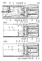
- Fig. 1 einen Längsschnitt durch ein erstes Ausführungsbeispiel eines erfindungsgemäßen Steckereinsatzes im zusammengesetzten Zustand;
- Fig. 2 einen Längsschnitt ähnlich Fig. 1 durch ein zweites Ausführungsbeispiel und
- Fig. 3 einen Längsschnitt ähnlich Fig. 1 durch ein drittes Ausführungsbeispiel.
- Figure 1 shows a longitudinal section through a first embodiment of a plug insert according to the invention in the assembled state.
- Fig. 2 shows a longitudinal section similar to Fig. 1 through a second embodiment and
- Fig. 3 shows a longitudinal section similar to Fig. 1 through a third embodiment.
Ein Ausführungsbeispiel eines erfindungsgemäßen Steckereinsatzes für ein zylindrisches Metallrohrgehäuse 10 umfaßt eine von einem vorderen Ende 12 des Metallrohrgehäuses 10 in dieses einführbare zylindrische Schutzhülse 14, welche einen vorderen, auf einer am vorderen Ende 12 angeordneten Stirnfläche 16 im eingeschobenen Zustand aufliegenden Bund 18 aufweist. Dieser Bund 18 ist vorzugsweise mit einem mit dem Metallrohrgehäuse 10 identischen Außendurchmesser versehen. Durch diesen Bund 18 wird die Lage der Schutzhülse 14 im in Fig. 1 dargestellten eingeschobenen Zustand definiert.An exemplary embodiment of a plug insert according to the invention for a cylindrical
Die Schutzhülse 14 ist in der Art eines Zylindermantels geformt und weist eine zylindrische Innenwandfläche 20 auf.The
In diese Schutzhülse 14 ist ein als Ganzes mit 22 bezeichneter Kontaktträger von seiten des Bundes 18 einführbar, welcher eine Kontaktträgerplatte 24 umfaßt, welche im in die Schutzhülse 14 eingeschobenen Zustand eine erste, dem Bund 16 zugewandte Seite 26 und eine zweite, dem Bund 16 abgewandte Seite 28 aufweist. Ferner steht über die erste Seite 26 von der Kontaktträgerplatte 24 ein zylindrischer Ansatz 30 in Richtung des Bundes 18 vor, welcher einstückig an die Kontaktträgerplatte 24 angeformt ist und gemeinsam mit dieser eine zylindrische Außenfläche 32 bildet, mit welcher der Kontaktträger 22 an der Innenwandfläche 20 der Schutzhülse 14 geführt ist.In this
Zur definierten Fixierung des Kontaktträgers 22 weist die Schutzhülse 14 einen von der Innenwandfläche 20 nach innen überstehenden Ringbund 33 auf, welcher auf seiner dem Bund 18 zugewandten Seite eine konisch in Richtung auf die Innenwandfläche 20 abfallende Ringfläche 34 aufweist und zusätzlich eine zur Innenwandfläche 20 parallele Innenfläche 36.For the defined fixation of the
Entsprechend ist die Kontaktträgerplatte 24 geformt. Sie weist eine sich an die zylindrische Außenfläche 32 anschließende konisch radial nach innen verlaufende und an der Ringfläche 34 zur Anlage bringbare Ringfläche 38 auf sowie eine sich an die Ringfläche 38 anschließende und an der Innenfläche 36 die Kontaktträgerplatte 24 zentriert haltende Außenfläche 40.The
Der Kontaktträger 22 ist somit vom Bund 16 her so weit in die Schutzhülse 14 einschiebbar, bis die Ringfläche 34 und die Ringfläche 38 miteinander zur Anlage kommen.The
Die Position des Kontaktträgers 22 wird bestimmt durch sich von der ersten Seite 26 von der Kontaktträgerplatte 24 weg erstreckenden Steckerstifte 42, welche sich bis zum Bund 18 erstrecken sollen und vorzugsweise unmittelbar vor einer Vorderseite 44 der Schutzhülse 14 enden. Die Steckerstifte 42 erstrecken sich dabei parallel zu einer Längsachse 46 des Metallrohrgehäuses 10 und der Schutzhülse 14 in einer ersten Richtung 45, während sich die Lötanschlüsse 48 entgegengesetzt zur ersten Richtung 45 in einer zweiten Richtung 47 parallel zur Längsachse erstrecken. In dieser Richtung erstreckt sich auch ein die gesamte Innenwandfläche 20 abdeckender Schutzkragen 52.The position of the
Des weiteren erheben sich von der zweiten Seite 28 der Kontaktträgerplatte 24 den Steckerstiften 42 zugeordnete Lötanschlüsse 48, an welche innen das Metallrohrgehäuse führende und lediglich strichpunktiert dargestellte Verbindungskabel 50 anlötbar sind.Furthermore, from the
Der Schutzkragen 52 wird gebildet durch den sich in der zweiten Richtung 47 von der zweiten Seite 28 weg erstreckenden Abschnitt 52 der Schutzhülse 14, welcher Spannungsüberschläge von den Lötanschlüssen 48 zu dem Metallrohrgehäuse 10 verhindern soll, wobei der Schutzkragen 52 eine von einem hinteren Ende 54 der Lötanschlüsse 48 zu dem Metallrohrgehäuse 10 führende Luftstrecke L möglichst groß halten soll.The
Bevorzugterweise ist vorgesehen, daß die Luftstrecke L mehr als 5 mm beträgt. Somit erstreckt sich der Schutzkragen 52 um mindestens 5 mm von dem hinteren Ende 54 der Lötanschlüsse 48 von der zweiten Seite 28 weg in Richtung der Längsachse 46.It is preferably provided that the air gap L is more than 5 mm. The
Die Montage des erfindungsgemäßen Steckereinsatzes erfolgt nun dadurch, daß zunächst bei nicht in die Schutzhülse 14 eingesetztem Kontaktträger 22 ein Verlöten der Kabel 50 mit den Lötanschlüssen 48 erfolgt, daß dann der Kontaktträger 22 vom Bund 18 her in die Schutzhülse 14 eingeführt und an dem Ringbund 32 vorzugsweise durch Preßpassung, wie in Fig. 1 dargestellt, fixiert wird.The plug insert according to the invention is now assembled by first soldering the
Alternativ kann, wie in Fig. 2 dargestellt, eine Einschnappverbindung vorgesehen sein, wozu vorzugsweise in Höhe der zweiten Seite 28 die Kontaktträgerplatte mit radial nach außen stehenden Klauen 60 versehen ist, welche in entsprechende Ausnehmungen 62 in der Innenfläche 36 des Ringbundes 32 eingreifen und damit ein Bewegen der Kontaktträgerplatte 24 in Richtung des Bundes 18 verhindern.Alternatively, as shown in FIG. 2, a snap-in connection can be provided, for which purpose the contact carrier plate is preferably provided at the level of the
Bei einem dritten Ausführungsbeispiel, dargestellt in Fig. 3, erfolgt ein Verschweißen des Kontaktträgers 22 mit der Schutzhülse 14 im Berührungsbereich der der Innenwandfläche 20 zugewandten Außenfläche 32 des zylindrischen Ansatzes 30 mit der Innenwandfläche 20 der Schutzhülse 14, wobei eine Schweißstelle 66 entsteht, die vorzugsweise entlang der Innenwandfläche 20 umläuft.In a third exemplary embodiment, shown in FIG. 3, the
Insbesondere dann, wenn - wie in Fig. 1 dargestellt - in der Schutzhülse 14 Anzeigeelemente 68 vorgesehen sind, ist die Schutzhülse 14 aus einem durchscheinenden oder durchsichtigen Werkstoff hergestellt.In particular, if — as shown in FIG. 1 —
Claims (10)
dadurch gekennzeichnet,
daß die Schutzhülse (14) und der Kontaktträger (22) zwei zusammensetzbare Teile sind, daß die Schutzhülse (14) eine Aufnahme (32) aufweist, in welche der Kontaktträger (22) einsetzbar und fixierbar ist, und daß bei in die Schutzhülse (14) eingesetztem Kontaktträger (22) der Schutzkragen (52) in der zweiten Richtung (47) über die Lötanschlüsse (48) übersteht.1. Plug insert for a metal tube housing, comprising a contact carrier, from which plug pins protrude from a first side and solder connections from a first opposite second side, a protective sleeve surrounding the contact carrier and insertable into the metal tube, which extends from the first side of the contact carrier in a extends in the first direction parallel to the connector pins with its front side and in a second direction, opposite to the first, forms a protective collar projecting beyond the second side of the contact carrier,
characterized,
that the protective sleeve (14) and the contact carrier (22) are two parts that can be assembled, that the protective sleeve (14) has a receptacle (32) into which the contact carrier (22) can be inserted and fixed, and that in the protective sleeve (14 ) inserted contact carrier (22) the protective collar (52) in the second direction (47) over the solder connections (48).
Applications Claiming Priority (2)
| Application Number | Priority Date | Filing Date | Title |
|---|---|---|---|
| DE3928791 | 1989-08-31 | ||
| DE3928791A DE3928791A1 (en) | 1989-08-31 | 1989-08-31 | PLUG INSERT FOR A METAL PIPE HOUSING |
Publications (2)
| Publication Number | Publication Date |
|---|---|
| EP0415136A1 true EP0415136A1 (en) | 1991-03-06 |
| EP0415136B1 EP0415136B1 (en) | 1995-03-08 |
Family
ID=6388247
Family Applications (1)
| Application Number | Title | Priority Date | Filing Date |
|---|---|---|---|
| EP90115124A Expired - Lifetime EP0415136B1 (en) | 1989-08-31 | 1990-08-07 | Connector insert for a metallic housing |
Country Status (4)
| Country | Link |
|---|---|
| US (1) | US5062810A (en) |
| EP (1) | EP0415136B1 (en) |
| JP (1) | JPH0393177A (en) |
| DE (2) | DE3928791A1 (en) |
Cited By (2)
| Publication number | Priority date | Publication date | Assignee | Title |
|---|---|---|---|---|
| FR2732166A1 (en) * | 1995-03-22 | 1996-09-27 | Blue Moon Ww Sa | REGULATED CONNECTOR HOUSING |
| EP1636881A1 (en) * | 2003-06-25 | 2006-03-22 | Friwo Geraetebau GmbH | Plug-in connection for a mobile terminal |
Families Citing this family (5)
| Publication number | Priority date | Publication date | Assignee | Title |
|---|---|---|---|---|
| US5580273A (en) * | 1995-05-11 | 1996-12-03 | Caterpillar Inc. | Hydraulic electrode seal |
| DE29910960U1 (en) | 1999-06-23 | 1999-10-28 | Leuze Electronic Gmbh + Co, 73277 Owen | Connectors |
| DE10013218C2 (en) * | 2000-03-17 | 2003-06-05 | Balluff Gmbh | Method for producing a position sensor and position sensor |
| US6857902B2 (en) * | 2001-02-21 | 2005-02-22 | I F M Electronics Gmbh | Proximity switch and a cable terminal part unit and a process for its manufacture |
| DE102014112658B4 (en) | 2014-09-03 | 2018-05-30 | FILTEC GmbH Filtertechnologie für die Elektronikindustrie | Plug for a connector for data cables |
Citations (2)
| Publication number | Priority date | Publication date | Assignee | Title |
|---|---|---|---|---|
| GB1520387A (en) * | 1975-12-16 | 1978-08-09 | Wolf Kg F | Electric plug connector member |
| DE3730033A1 (en) * | 1987-09-08 | 1989-03-16 | Dietrich Gebhard | Plug for a plug connection for the electrical connection of motor vehicle trailers |
Family Cites Families (7)
| Publication number | Priority date | Publication date | Assignee | Title |
|---|---|---|---|---|
| CA364827A (en) * | 1937-03-16 | Von Fraunhofer Hans | Photographic film | |
| US1086338A (en) * | 1913-06-30 | 1914-02-03 | Charles L Sherman | Insulating-lining. |
| US1281907A (en) * | 1915-11-27 | 1918-10-15 | Bryant Electric Co | Current-tap. |
| US3034092A (en) * | 1959-10-06 | 1962-05-08 | United Carr Fastener Corp | Connector and mounting bracket therefor |
| DE3123594A1 (en) * | 1981-06-13 | 1983-01-05 | Gebhard Balluff, Fabrik Feinmechanischer Erzeugnisse, 7303 Neuhausen | Proximity switch |
| DE8413226U1 (en) * | 1984-04-30 | 1984-08-02 | Preh, Elektrofeinmechanische Werke Jakob Preh Nachf. Gmbh & Co, 8740 Bad Neustadt | Diode connector |
| DE3727375A1 (en) * | 1987-08-17 | 1989-03-02 | Interconnectron Gmbh | ELECTRICAL PLUG |
-
1989
- 1989-08-31 DE DE3928791A patent/DE3928791A1/en active Granted
-
1990
- 1990-08-07 EP EP90115124A patent/EP0415136B1/en not_active Expired - Lifetime
- 1990-08-07 DE DE59008627T patent/DE59008627D1/en not_active Expired - Fee Related
- 1990-08-27 US US07/573,901 patent/US5062810A/en not_active Expired - Fee Related
- 1990-08-30 JP JP2226793A patent/JPH0393177A/en active Pending
Patent Citations (2)
| Publication number | Priority date | Publication date | Assignee | Title |
|---|---|---|---|---|
| GB1520387A (en) * | 1975-12-16 | 1978-08-09 | Wolf Kg F | Electric plug connector member |
| DE3730033A1 (en) * | 1987-09-08 | 1989-03-16 | Dietrich Gebhard | Plug for a plug connection for the electrical connection of motor vehicle trailers |
Cited By (3)
| Publication number | Priority date | Publication date | Assignee | Title |
|---|---|---|---|---|
| FR2732166A1 (en) * | 1995-03-22 | 1996-09-27 | Blue Moon Ww Sa | REGULATED CONNECTOR HOUSING |
| US5796036A (en) * | 1995-03-22 | 1998-08-18 | Blue Moon Ww | Reguided connector box |
| EP1636881A1 (en) * | 2003-06-25 | 2006-03-22 | Friwo Geraetebau GmbH | Plug-in connection for a mobile terminal |
Also Published As
| Publication number | Publication date |
|---|---|
| EP0415136B1 (en) | 1995-03-08 |
| DE59008627D1 (en) | 1995-04-13 |
| DE3928791A1 (en) | 1991-03-14 |
| DE3928791C2 (en) | 1992-01-30 |
| US5062810A (en) | 1991-11-05 |
| JPH0393177A (en) | 1991-04-18 |
Similar Documents
| Publication | Publication Date | Title |
|---|---|---|
| DE69500741T2 (en) | Micro-miniature coaxial connector with snap fastening | |
| DE3823617C2 (en) | ||
| DE2549597A1 (en) | COUPLING ARRANGEMENT FOR CONNECTABLE ENDS OF ELECTRIC CABLES | |
| DE2215757C3 (en) | Male or female part of a connector for coaxial cables | |
| DE4226904C2 (en) | Crimp sleeve | |
| DE102004062378B4 (en) | Cable feedthrough structure and wiring harness | |
| EP0415136B1 (en) | Connector insert for a metallic housing | |
| EP1671399B1 (en) | Shield connection | |
| DE2123053A1 (en) | Plug connections shielded against high-frequency interference for a multi-core cable | |
| DE2406417A1 (en) | ELECTRICAL CONNECTOR FOR CONNECTING A COAXIAL CABLE TO A PRINTED CIRCUIT BOARD | |
| DE4240261C2 (en) | Connectors | |
| DE10045263B4 (en) | connectors | |
| DE10237666B4 (en) | connector element | |
| DE29722987U1 (en) | Cable gland for cables with shielding sheath | |
| DE3341356A1 (en) | Coaxial-cable connecting device | |
| DE19525801C2 (en) | Device for the electrically conductive connection of two electrical lines | |
| DE19936508A1 (en) | Pluggable connector for connecting with contacts of associated counter piece e.g. for motor controls, uses additional protective conductor with one end located on protective conductor contact of contact insert | |
| DE3730432C1 (en) | Locking spring as a screened connection | |
| DE3700583C2 (en) | ||
| DE1918124A1 (en) | Electrical connection device | |
| DE4407583C1 (en) | Electrical connecting part | |
| DE3730431C2 (en) | ||
| DE2707254C2 (en) | Electric clutch | |
| EP0599119B1 (en) | Device for contacting the central conductor of a coaxial high frequency cable | |
| EP0527403B1 (en) | Connecting part, such as a plug or socket, preferably for miniature audio connectors |
Legal Events
| Date | Code | Title | Description |
|---|---|---|---|
| PUAI | Public reference made under article 153(3) epc to a published international application that has entered the european phase |
Free format text: ORIGINAL CODE: 0009012 |
|
| AK | Designated contracting states |
Kind code of ref document: A1 Designated state(s): CH DE FR GB IT LI |
|
| 17P | Request for examination filed |
Effective date: 19910415 |
|
| 17Q | First examination report despatched |
Effective date: 19930921 |
|
| GRAA | (expected) grant |
Free format text: ORIGINAL CODE: 0009210 |
|
| AK | Designated contracting states |
Kind code of ref document: B1 Designated state(s): CH DE FR GB IT LI |
|
| PG25 | Lapsed in a contracting state [announced via postgrant information from national office to epo] |
Ref country code: IT Free format text: LAPSE BECAUSE OF FAILURE TO SUBMIT A TRANSLATION OF THE DESCRIPTION OR TO PAY THE FEE WITHIN THE PRE;WARNING: LAPSES OF ITALIAN PATENTS WITH EFFECTIVE DATE BEFORE 2007 MAY HAVE OCCURRED AT ANY TIME BEFORE 2007. THE CORRECT EFFECTIVE DATE MAY BE DIFFERENT FROM THE ONE RECORDED.SCRIBED TIME-LIMIT Effective date: 19950308 Ref country code: FR Effective date: 19950308 Ref country code: GB Effective date: 19950308 |
|
| REF | Corresponds to: |
Ref document number: 59008627 Country of ref document: DE Date of ref document: 19950413 |
|
| EN | Fr: translation not filed | ||
| PG25 | Lapsed in a contracting state [announced via postgrant information from national office to epo] |
Ref country code: CH Effective date: 19950831 Ref country code: LI Effective date: 19950831 |
|
| GBV | Gb: ep patent (uk) treated as always having been void in accordance with gb section 77(7)/1977 [no translation filed] |
Effective date: 19950308 |
|
| PLBI | Opposition filed |
Free format text: ORIGINAL CODE: 0009260 |
|
| PLBQ | Unpublished change to opponent data |
Free format text: ORIGINAL CODE: EPIDOS OPPO |
|
| PLBF | Reply of patent proprietor to notice(s) of opposition |
Free format text: ORIGINAL CODE: EPIDOS OBSO |
|
| 26 | Opposition filed |
Opponent name: IFM ELECTRONIC GMBH Effective date: 19951208 |
|
| PLBF | Reply of patent proprietor to notice(s) of opposition |
Free format text: ORIGINAL CODE: EPIDOS OBSO |
|
| REG | Reference to a national code |
Ref country code: CH Ref legal event code: PL |
|
| PLBL | Opposition procedure terminated |
Free format text: ORIGINAL CODE: EPIDOS OPPC |
|
| PLBM | Termination of opposition procedure: date of legal effect published |
Free format text: ORIGINAL CODE: 0009276 |
|
| STAA | Information on the status of an ep patent application or granted ep patent |
Free format text: STATUS: OPPOSITION PROCEDURE CLOSED |
|
| 27C | Opposition proceedings terminated |
Effective date: 19960930 |
|
| PGFP | Annual fee paid to national office [announced via postgrant information from national office to epo] |
Ref country code: DE Payment date: 20040927 Year of fee payment: 15 |
|
| PG25 | Lapsed in a contracting state [announced via postgrant information from national office to epo] |
Ref country code: DE Free format text: LAPSE BECAUSE OF NON-PAYMENT OF DUE FEES Effective date: 20060301 |
|
| PLAB | Opposition data, opponent's data or that of the opponent's representative modified |
Free format text: ORIGINAL CODE: 0009299OPPO |