EP0647390A2 - Dispositif de traite automatique d'animaux - Google Patents
Dispositif de traite automatique d'animaux Download PDFInfo
- Publication number
- EP0647390A2 EP0647390A2 EP94202888A EP94202888A EP0647390A2 EP 0647390 A2 EP0647390 A2 EP 0647390A2 EP 94202888 A EP94202888 A EP 94202888A EP 94202888 A EP94202888 A EP 94202888A EP 0647390 A2 EP0647390 A2 EP 0647390A2
- Authority
- EP
- European Patent Office
- Prior art keywords
- construction
- milking
- floor
- collecting member
- teat
- Prior art date
- Legal status (The legal status is an assumption and is not a legal conclusion. Google has not performed a legal analysis and makes no representation as to the accuracy of the status listed.)
- Granted
Links
Images


Classifications
-
- A—HUMAN NECESSITIES
- A01—AGRICULTURE; FORESTRY; ANIMAL HUSBANDRY; HUNTING; TRAPPING; FISHING
- A01J—MANUFACTURE OF DAIRY PRODUCTS
- A01J5/00—Milking machines or devices
- A01J5/017—Automatic attaching or detaching of clusters
- A01J5/0175—Attaching of clusters
-
- A—HUMAN NECESSITIES
- A01—AGRICULTURE; FORESTRY; ANIMAL HUSBANDRY; HUNTING; TRAPPING; FISHING
- A01K—ANIMAL HUSBANDRY; CARE OF BIRDS, FISHES, INSECTS; FISHING; REARING OR BREEDING ANIMALS, NOT OTHERWISE PROVIDED FOR; NEW BREEDS OF ANIMALS
- A01K1/00—Housing animals; Equipment therefor
- A01K1/12—Milking stations
-
- A—HUMAN NECESSITIES
- A01—AGRICULTURE; FORESTRY; ANIMAL HUSBANDRY; HUNTING; TRAPPING; FISHING
- A01K—ANIMAL HUSBANDRY; CARE OF BIRDS, FISHES, INSECTS; FISHING; REARING OR BREEDING ANIMALS, NOT OTHERWISE PROVIDED FOR; NEW BREEDS OF ANIMALS
- A01K23/00—Manure or urine pouches
- A01K23/005—Manure or urine collecting devices used independently from the animal, i.e. not worn by the animal but operated by a person
Definitions
- the invention relates to a construction for milking animals, such as cows, comprising a milking robot for automatically connecting teat cups to the teats of an animal.
- the teat cups are usually disposed on a robot arm. Prior to and after milking, the teat cups are in a position next to the milking box. In this stage, dirt can penetrate into the teat cups.
- the invention has for its object to provide a construction of the above-described type, in which said disadvantage does not occur or is at least obviated to a significant extent.
- this is achieved in that near the upper end of the teat cup a removable cover for at least this teat cup is disposed.
- a removable cover is disposed near the upper end of the teat cups.
- the milking robot head is provided with a covering member which is slidable over the upper end of the teat cups.
- the construction in accordance with the invention includes a movable collecting member for collecting the excrements of an animal present in the construction, which member is disposed at the trailing side of the construction.
- the invention also relates to a construction for milking animals, such as cows, comprising a milking robot for automatically milking animals, characterized in that a movable collecting member for collecting the excrements of an animal present in the construction is arranged at the rear side of the construction.
- the collecting member is placed just above the floor of the construction. In this manner, the rate of fall of the excrements can be kept low.
- the invention also relates to a construction for milking animals, such as cows, comprising a milking robot for automatically milking animals, characterized in that the construction includes a collecting member for collecting the excrements of an animal present in the construction placed just above the floor of the construction.
- the collecting member is further characterized in that it is so connected with the aid of a four-bar linkage that it can be moved in the longitudinal direction of the construction, and the entrance door of the construction is positioned in a longitudinal side thereof.
- the bottom of the collecting member extends rearwardly and obliquely downwards. Splashing of the dung on hitting the bottom is thereby limited to a minimum.
- the collecting member includes, in accordance with a still further feature of the invention, a flexible pipe which is connected to a discharge system.
- the construction in accordance with the invention is provided at its leading end with a movable feed trough connected to an automatic feeding implement.
- the invention therefore, also relates to a construction for milking animals, such as cows, comprising a milking robot for automatically milking animals, characterized in that at the leading side of the construction a movable feed trough is disposed, whilst at the trailing side of the construction a movable collecting member for excrements of an animal is arranged.
- the feed trough is connected via a flexible pipe to an automatic feeding implement.
- the feed trough is connected to the leading side of the construction in such a manner that it is movable with the aid of a four-bar linkage in the longitudinal direction of the construction, and the exit door of the construction is provided in a longitudinal side thereof.
- the entrance door and the exit door of the construction are located at one longitudinal side, whilst the milking robot is movably arranged at or near the other longitudinal side thereof.
- the floor of the milking box includes one or more slats of such a design that they form a continuous floor portion, as well as one or more slats of such a design that they form a grid floor.
- the invention also relates to a construction for milking animals, such as cows, comprising a milking robot for automatically milking animals, characterized in that the floor thereof includes one or more slats forming a continuous floor, as well as one or more slats forming a grid floor.
- two slats are arranged such as to form a continuous floor, whilst between these two slats there is a grid floor, under which a discharge system for the dung is located at least partly, to which also the flexible pipe of the collecting member is connected.
- Figure 1 is a side view of a milking box 1, in which the contours of a cow are shown.
- the milking box 1 includes a railing 2 and is provided at one side with an entrance door 3 and an exit door 4 ( Figure 2).
- the railing 2 of the milking box 1 is fitted with a longitudinal straight guide 5, which has one end connected to a girder 6 of the milking box 1 and its other end to the side wall of the railing 2.
- a milking robot 8 Attached to the sleeve 7 is a milking robot 8 which by shifting of the sleeve 7 moves the milking robot 8 in the longitudinal direction of the milking box 1.
- a second beam 12 is arranged parallel to the beam 10, at some distance therefrom by means of a four-bar linkage 11. Using a cylinder (not shown), the second beam 12 can be moved relative to the first beam 10 in a horizontal plane, so that a robot head 13, which comprises teat cups 14 to 17 and is attached to the end of the beam 12, can be moved transversely in the milking box.
- the milking robot head 13 is provided with a cover plate 18 which is slidable towards the teat cups and which, when the teat cups 14 to 17 are not connected to the teats, covers the apertures of the teat cups.
- a movable detector 19 is disposed, which preferably is constituted by a laser. The position of the teats of an animal to be milked standing in the milking box 1 can be determined with the aid of the detector 19.
- the detector 19 is connected to a second longitudinal straight guide 20, which renders it possible to slide the detector 19 in the longitudinal direction of the box.
- the second longitudinal straight guide 20 comprises two spaced-apart rods 21, which are arranged one below the other next to the milking box 1 and have one end connected to the railing 2 of the milking box 1 via two girders 22.
- a second sleeve 23 is disposed in such a manner around the two longitudinal straight guides 20 that it is slidable in the longitudinal direction of the milking box 1.
- the second sleeve 23 can be moved along the two longitudinal straight guides 20 by means of a threaded spindle, which is inserted between the two longitudinal straight guides 20 and through the sleeve 23 and is driven by a stepping motor 25.
- the second sleeve 23 is provided with an arm 26 which at its end is provided with a second four-bar linkage 27, to which, extending transversely of the longitudinal direction of the milking box 1, a U-shaped holder 28 is attached.
- the detector 19 is clamped pivotally about a vertical shaft 29, between the U-shaped holder 28.
- the detector 19 can be pivoted about the vertical shaft 29 by means of a stepping motor 30 disposed on top of the U-shaped holder 28.
- the detector 29 is comprised of a vertically arranged cylindrical housing, on top of which a truncated cone-shaped jacket 31 is placed at a square angle.
- the cylindrical housing 19 accommodates a laser, which transmits a signal via a window in this housing and through the truncated cone-shaped jacket 31.
- the detector may alternatively be formed by e.g. an ultrasonic sensor.
- the truncated coneshaped jacket 31 shields the window in the detector 19, so that the laser and/or e.g. the ultrasonic sensor will not so easily be put out of order by contamination.
- the detector 19 can be moved in the longitudinal direction of the milking box 1, it is also possible for the detector to be moved in height by means of a stepping motor (not shown), using the second four-bar linkage 27.
- a feeding trough 32 Near the leading side of the milking box 1 there is further arranged a feeding trough 32, which has at its upper side a flexible tube 33 which is connected to an automatic concentrate dosing device (not shown), for automatically discharging concentrate into the feeding trough 32.
- the feeding trough 32 is connected to a vertically arranged third four-bar linkage 34, which has its other end connected to a beam 35 connected horizontally to the railing 2.
- a cylinder (not shown) which is connected to an arm of the third four-bar linkage 34, the feeding trough can be swivelled from the milking box 1 to thereoutside, so that the cow can no longer eat from the feeding trough 32.
- the milking box 1 further incorporates, arranged near its trailing end, a dung collecting member 36.
- the dung collecting member 36 includes a container 37 which has a bottom 38 which extends obliquely downwardly from the cow.
- the bottom 38 encloses an angle of preferably approximately 20° with the horizontal.
- a flexible discharge pipe 39 Connected to the lowest part of the bottom 38 there is a flexible discharge pipe 39 which leads to a dung cellar (not shown) under the milking box 1.
- the container 37 is connected to a vertically arranged fourth four-bar linkage 40, which has its other side connected to the floor 41 of the milking box 1.
- the floor 41 is provided in the region of the cows legs, with slats 42 which together form a continuous floor. Between and next to the slats 42, the floor 41 is further designed as a grid floor 43.
- the dung cellar (not shown) is located under the grid floor 43, so that dirt drops into the dung cellar via the grid 43.
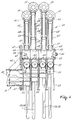
- Figures 3 to 8 are further illustrations of the construction of the robot head 13.
- Figure 4 shows a portion of the second beam 12 of the milking robot 8, and it is shown that the second beam 12 is provided at its end with a plate 44, by means of which the robot head 13 is secured to the second beam 12.
- a stay rod 45 is arranged between the plate 44 and the second beam 12.
- the robot head 13 also includes a mounting plate 46 which corresponds to the plate 44 and is detachably bolted to the plate 44 by means of bolts 47.
- a box-like supporting beam 48 In a position perpendicular to the mounting plate 46 there is a box-like supporting beam 48, around which four units 49 are pushed which are locked by means of an end plate 50 with a bolt 51.
- the structure of each of the units 49 will now be described in greater detail with reference to Figure 3.
- Each unit 49 includes a box-like carrier beam 52, which can be pushed over the supporting beam 48.
- the carrier beam 52 is provided with two spaced-apart plates 53, between which a connecting block 54 for a milk and pulsation tube 55, 56 is secured.
- two spaced-apart lugs 57 are disposed, to which a rod system 58 forming a deformable quadrangle is connected.
- the rod system 58 which forms a deformable quadrangle, has its other end connected to a holder 59 for a teat cup (14; 15; 16; 17).
- Each of the holders 59 is assembled from two spaced-apart plates 60 which at their ends are interconnected so as to form a curved seat 61, against which a teat cup can bear.
- the plates 60 are secured on a tubular holder 62, in which a cylinder 43 is accommodated.
- a roller element 65 is disposed, around which a flexible cord 66 is passed.
- the cord 66 has one end connected to the tubular holder 62 and the other end to the teat cup.
- the cylinder 63 When a teat cup is to be disconnected from a teat, the cylinder 63 is energized, as a result of which the cord 66 is retracted into the tubular holder 62, whereafter the teat cup is pulled up against the seat 61.
- two spaced-apart lugs 67 are attached, between which, pivotal about a horizontal shaft 68, a nut 69 is clamped.
- a threaded end 70 Inserted through the nut 69 is a threaded end 70, which has one end connected to a stepping motor 71.
- the stepping motor 71 is clamped between the plates 53 and is rotatable about a horizontal shaft 72.
- each of the units 49 can be replaced individually when getting out of order.
- the milk tube 55 and the pulsation tube 56 are wrapped together by a wrapping 73.
- the wrapping 73 may be in the form of a length of tape, an iron wire, a bandage, etc. Because of the wrapping 73, the first portion 74 of the milk and pulsation tubes 55, 56, which extend from the teat cup to just behind the plates 53, is relatively rigid and consequently oriented more or less in a horizontal plane.
- the second portion 75 of the milk and pulsation tubes 55, 56 extends in the shape of a loop and is located in a vertical plane.
- the second portion 75 of the milk and pulsation tubes 55, 56 is relatively flexible.
- the first portion 74 will therefore bend to a minimum extent, whilst the second portion 75 bends relatively much. Since the first portion 74 is relatively rigid, the milk and pulsation tubes 55, 56 will be prevented from sagging and landing on the floor 41 of the milking box 1.
- An additional advantage is that, consequently, the head 13 of the milking robot can be moved at a relatively low level along the floor 41, without portions of the milking robot 8 coming into contact with the floor 41 of the milking box 1.
- the teat cups are pivotal about an upwardly directed shaft with the aid of a pivotal structure 76.
- the pivotal structure 76 includes a tube 77 attached to the ends of the plates 60.
- a pivotal shaft 78 is passed through the tube 77, which tube is connected at its bottom side to a stepping motor 79, which itself is rigidly connected to the tubular holder 62 via a support 80.
- the seat 61 of the teat cup is rigidly connected by means of lugs 81 to the pivotal shaft 78.
- By energizing the stepping motor 79 it is possible to rotate the seat 61 with the teat cup around the shaft 78.
- teats which are very remote from each other, which e.g. in a plan view are arranged more or less in a square, can easily be reached by the teat cups 14 to 17 without the teat cups forming an obstruction to each other.
- the stepping motor 30 is energized, so that the detector is pivoted about the vertical shaft 29.
- the detector 19 is preferably pivoted through an angle of approximately 25°.
- the robot head 13 is pivoted to under the cow and, using the four-bar linkage 11, the robot head 13 is positioned in the lateral direction of the milking box 1.
- the teat cups 14 to 17, by energizing the stepping motor 71 are moved to the central position as shown in Figure 3.
- the robot head is moved in the longitudinal direction of the milking box 1 along the longitudinal straight guide 5, and the teat cup 14 is positioned under the left-hand rear teat.
- the stepping motor 71 of the teat cup 14 is then energized again, whereafter the teat cup 14 is lifted upwardly, as shown in Figure 5.
- this cup is connected by this vacuum to the left-hand rear teat and thereafter the cylinder 63 of the teat cup 14 is disabled, so that the teat cup can get loose from the seat 61.
- the teat cups 15, 16 and 17 are connected in the same manner one after the other to the further teats of the cow.
- the teat cups 14 to 17 are arranged during milking.
- the teat cup 14 is inadvertently kicked from the teat or gets disconnected therefrom in any other way, the teat cup is immediately pulled up against the seat 61 of the relevant holder 59. So as to be able to connect the cup 14 again without the need for the cup 17 to be removed, the holder 59 of the teat cup 17 is thereafter pivoted downwards by means of the stepping motor 71 to the position shown in Figure 6. The holder 59 of the teat cup 17 is then in the position shown in Figure 7 by broken lines. Thereafter the holder 59 of the teat cup 14 is again moved towards the left-hand rear teat, all this in such a manner that the teat cup 14 arrives in a position such that its aperture is in a position under the left-hand rear teat.
- the stepping motor 71 is energized again and the teat cup 14 is moved up and is connected to the teat.
- the robot head 13 can then again be moved away from the teat, so that the initial situation, such as it is shown at the right-hand half of Figure 7, is obtained.
- the teat cup 14 is then again in the connected state, without the need for disconnecting the further teat cups. It will be obvious that this procedure results in a considerable gain in time, and that the milking procedure of the other quarters need not be interrupted when the disconnected cup is to be connected to the teat again.
Priority Applications (2)
| Application Number | Priority Date | Filing Date | Title |
|---|---|---|---|
| EP00201926A EP1029447B1 (fr) | 1993-10-11 | 1994-10-05 | Dispositif de traite automatique d'animaux |
| DE9422280U DE9422280U1 (de) | 1993-10-11 | 1994-10-05 | Vorrichtung zum Melken von Tieren |
Applications Claiming Priority (2)
| Application Number | Priority Date | Filing Date | Title |
|---|---|---|---|
| NL9301753A NL9301753A (nl) | 1993-10-11 | 1993-10-11 | Inrichting voor het automatisch melken van dieren. |
| NL9301753 | 1993-10-11 |
Related Child Applications (1)
| Application Number | Title | Priority Date | Filing Date |
|---|---|---|---|
| EP00201926A Division EP1029447B1 (fr) | 1993-10-11 | 1994-10-05 | Dispositif de traite automatique d'animaux |
Publications (3)
| Publication Number | Publication Date |
|---|---|
| EP0647390A2 true EP0647390A2 (fr) | 1995-04-12 |
| EP0647390A3 EP0647390A3 (fr) | 1995-06-14 |
| EP0647390B1 EP0647390B1 (fr) | 2000-12-06 |
Family
ID=19862995
Family Applications (2)
| Application Number | Title | Priority Date | Filing Date |
|---|---|---|---|
| EP94202888A Expired - Lifetime EP0647390B1 (fr) | 1993-10-11 | 1994-10-05 | Dispositif de traite automatique d'animaux |
| EP00201926A Revoked EP1029447B1 (fr) | 1993-10-11 | 1994-10-05 | Dispositif de traite automatique d'animaux |
Family Applications After (1)
| Application Number | Title | Priority Date | Filing Date |
|---|---|---|---|
| EP00201926A Revoked EP1029447B1 (fr) | 1993-10-11 | 1994-10-05 | Dispositif de traite automatique d'animaux |
Country Status (3)
| Country | Link |
|---|---|
| EP (2) | EP0647390B1 (fr) |
| DE (4) | DE69434780T2 (fr) |
| NL (1) | NL9301753A (fr) |
Cited By (15)
| Publication number | Priority date | Publication date | Assignee | Title |
|---|---|---|---|---|
| EP0811319A1 (fr) * | 1996-06-05 | 1997-12-10 | Westfalia Separator AG | Dispositif de mise en place et méthode pour la mise en place de gobelets de traite |
| WO1998005201A2 (fr) * | 1996-08-01 | 1998-02-12 | Maasland N.V. | Appareil pour la traite automatique d'animaux |
| WO1999031970A1 (fr) * | 1997-12-19 | 1999-07-01 | Alfa Laval Agri Ab | Dispositif en rapport avec un animal |
| WO1999031971A1 (fr) * | 1997-12-23 | 1999-07-01 | Alfa Laval Agri Ab | Installation et procede de gestion d'un troupeau d'animaux |
| NL1009075C2 (nl) * | 1998-05-06 | 1999-11-09 | Maasland Nv | Melkbeker en melkrobot voorzien van de melkbeker. |
| NL1015671C2 (nl) * | 2000-07-10 | 2002-01-11 | Lely Entpr Ag | Inrichting voor het automatisch melken van dieren. |
| NL1016023C2 (nl) * | 2000-08-25 | 2002-02-26 | Idento Electronics Bv | Melkinrichting en houder voor opname van melkbekers. |
| NL1019117C2 (nl) * | 2001-10-05 | 2003-04-09 | Lely Entpr Ag | Inrichting en werkwijze voor het uitvoeren van een diergerelateerde behandeling op een dier. |
| US9426966B2 (en) | 2011-03-18 | 2016-08-30 | Gea Farm Technologies Gmbh | Milking cluster and milking parlor having such a milking cluster |
| US9918450B2 (en) | 2012-03-14 | 2018-03-20 | Gea Farm Technologies Gmbh | Space divider of a milking parlor arrangement, and milking parlor arrangement |
| US9968069B2 (en) | 2011-03-18 | 2018-05-15 | Gea Farm Technologies Gmbh | Milking cluster and milking parlor having such a milking cluster |
| US10440931B2 (en) | 2014-05-20 | 2019-10-15 | Gea Farm Technologies Gmbh | Arm device for a milking parlor arrangement for the automatic milking of milk-producing animals, divider for a milking parlor arrangement, and milking parlor arrangement |
| EP3240400B1 (fr) * | 2014-12-30 | 2020-05-27 | DeLaval Holding AB | Système de traite rotative |
| US10694717B2 (en) | 2012-03-14 | 2020-06-30 | Gea Farm Technologies Gmbh | Milking parlor arrangement with an inner robot device |
| US11464199B2 (en) | 2017-05-31 | 2022-10-11 | Delaval Holding Ab | End effector of a robot arm and arrangement for performing an animal related operation |
Families Citing this family (2)
| Publication number | Priority date | Publication date | Assignee | Title |
|---|---|---|---|---|
| NL1021157C2 (nl) * | 2002-07-25 | 2004-01-27 | A M De Rooy B V | Inrichting voor het behandelen van koeklauwen. |
| CN108935112B (zh) * | 2018-06-26 | 2021-06-22 | 绍兴柯桥韩丝针纺有限公司 | 一种具有自动净化空气效果的养牛棚 |
Citations (2)
| Publication number | Priority date | Publication date | Assignee | Title |
|---|---|---|---|---|
| EP0300582A1 (fr) * | 1987-07-23 | 1989-01-25 | C. van der Lely N.V. | Dispositif et procédé de traite d'un animal |
| EP0560438A2 (fr) * | 1992-03-06 | 1993-09-15 | C. van der Lely N.V. | Machine à traire pour le traite automatique d'animaux |
Family Cites Families (2)
| Publication number | Priority date | Publication date | Assignee | Title |
|---|---|---|---|---|
| US2779310A (en) * | 1953-08-12 | 1957-01-29 | Howard I Myer | Dairy stable sanitation equipment |
| US2779309A (en) * | 1954-10-12 | 1957-01-29 | Howard I Myer | Dairy stable sanitation equipment |
-
1993
- 1993-10-11 NL NL9301753A patent/NL9301753A/nl not_active Application Discontinuation
-
1994
- 1994-10-05 EP EP94202888A patent/EP0647390B1/fr not_active Expired - Lifetime
- 1994-10-05 EP EP00201926A patent/EP1029447B1/fr not_active Revoked
- 1994-10-05 DE DE69434780T patent/DE69434780T2/de not_active Expired - Lifetime
- 1994-10-05 DE DE9422280U patent/DE9422280U1/de not_active Expired - Lifetime
- 1994-10-05 DE DE69426379T patent/DE69426379T2/de not_active Expired - Lifetime
- 1994-10-15 DE DE00201926T patent/DE00201926T1/de active Pending
Patent Citations (2)
| Publication number | Priority date | Publication date | Assignee | Title |
|---|---|---|---|---|
| EP0300582A1 (fr) * | 1987-07-23 | 1989-01-25 | C. van der Lely N.V. | Dispositif et procédé de traite d'un animal |
| EP0560438A2 (fr) * | 1992-03-06 | 1993-09-15 | C. van der Lely N.V. | Machine à traire pour le traite automatique d'animaux |
Cited By (28)
| Publication number | Priority date | Publication date | Assignee | Title |
|---|---|---|---|---|
| EP0811319A1 (fr) * | 1996-06-05 | 1997-12-10 | Westfalia Separator AG | Dispositif de mise en place et méthode pour la mise en place de gobelets de traite |
| WO1998005201A2 (fr) * | 1996-08-01 | 1998-02-12 | Maasland N.V. | Appareil pour la traite automatique d'animaux |
| WO1998005201A3 (fr) * | 1996-08-01 | 1998-03-12 | Maasland Nv | Appareil pour la traite automatique d'animaux |
| AU724966B2 (en) * | 1996-08-01 | 2000-10-05 | Maasland N.V. | An implement for automatically milking animals |
| WO1999031970A1 (fr) * | 1997-12-19 | 1999-07-01 | Alfa Laval Agri Ab | Dispositif en rapport avec un animal |
| WO1999031971A1 (fr) * | 1997-12-23 | 1999-07-01 | Alfa Laval Agri Ab | Installation et procede de gestion d'un troupeau d'animaux |
| NL1009075C2 (nl) * | 1998-05-06 | 1999-11-09 | Maasland Nv | Melkbeker en melkrobot voorzien van de melkbeker. |
| WO1999056528A1 (fr) * | 1998-05-06 | 1999-11-11 | Maasland N.V. | Gobelets trayeurs et robot de traite equipe de ces gobelets |
| NL1015671C2 (nl) * | 2000-07-10 | 2002-01-11 | Lely Entpr Ag | Inrichting voor het automatisch melken van dieren. |
| EP1172029A1 (fr) * | 2000-07-10 | 2002-01-16 | Lely Enterprises AG | Construction pour la traite automatique d'animaux |
| US6948449B2 (en) | 2000-08-25 | 2005-09-27 | Idento Electronics B.V. | Milking apparatus and holder for receiving teat cups |
| WO2002015676A1 (fr) * | 2000-08-25 | 2002-02-28 | Idento Electronics B.V. | Appareil de traite et support de gobelets de traite |
| NL1016023C2 (nl) * | 2000-08-25 | 2002-02-26 | Idento Electronics Bv | Melkinrichting en houder voor opname van melkbekers. |
| NL1019117C2 (nl) * | 2001-10-05 | 2003-04-09 | Lely Entpr Ag | Inrichting en werkwijze voor het uitvoeren van een diergerelateerde behandeling op een dier. |
| EP1300068A3 (fr) * | 2001-10-05 | 2004-04-14 | Lely Enterprises AG | Dispositif et méthode pour réaliser un traitement sur un animal |
| US11013209B2 (en) | 2011-03-18 | 2021-05-25 | Gea Farm Technologies Gmbh | Milking cluster and milking parlor having such a milking cluster |
| US9848576B2 (en) | 2011-03-18 | 2017-12-26 | Gea Farm Technologies Gmbh | Milking cluster and milking parlor having such a milking cluster |
| US9968069B2 (en) | 2011-03-18 | 2018-05-15 | Gea Farm Technologies Gmbh | Milking cluster and milking parlor having such a milking cluster |
| US9426966B2 (en) | 2011-03-18 | 2016-08-30 | Gea Farm Technologies Gmbh | Milking cluster and milking parlor having such a milking cluster |
| US9918450B2 (en) | 2012-03-14 | 2018-03-20 | Gea Farm Technologies Gmbh | Space divider of a milking parlor arrangement, and milking parlor arrangement |
| US10694717B2 (en) | 2012-03-14 | 2020-06-30 | Gea Farm Technologies Gmbh | Milking parlor arrangement with an inner robot device |
| US10849304B2 (en) | 2012-03-14 | 2020-12-01 | Gea Farm Technologies Gmbh | Space divider of a milking parlor arrangement, and milking parlor arrangement |
| US11388882B2 (en) | 2012-03-14 | 2022-07-19 | Gea Farm Technologies Gmbh | Space divider of a milking parlor arrangement, and milking parlor arrangement |
| US11903363B2 (en) | 2012-03-14 | 2024-02-20 | Gea Farm Technologies Gmbh | Space divider of a milking parlor arrangement, and milking parlor arrangement |
| US10440931B2 (en) | 2014-05-20 | 2019-10-15 | Gea Farm Technologies Gmbh | Arm device for a milking parlor arrangement for the automatic milking of milk-producing animals, divider for a milking parlor arrangement, and milking parlor arrangement |
| EP3240400B1 (fr) * | 2014-12-30 | 2020-05-27 | DeLaval Holding AB | Système de traite rotative |
| US11464199B2 (en) | 2017-05-31 | 2022-10-11 | Delaval Holding Ab | End effector of a robot arm and arrangement for performing an animal related operation |
| EP3629712B1 (fr) * | 2017-05-31 | 2024-01-24 | DeLaval Holding AB | Effecteur terminal d'un bras robotisé et dispositif pour effectuer une opération en rapport avec un animal |
Also Published As
| Publication number | Publication date |
|---|---|
| NL9301753A (nl) | 1995-05-01 |
| DE69426379D1 (de) | 2001-01-11 |
| DE69434780D1 (de) | 2006-08-10 |
| EP1029447A3 (fr) | 2001-08-08 |
| EP1029447A2 (fr) | 2000-08-23 |
| DE9422280U1 (de) | 1999-10-07 |
| DE00201926T1 (de) | 2005-03-31 |
| DE69434780T2 (de) | 2007-06-14 |
| DE69426379T2 (de) | 2001-06-13 |
| EP1029447A8 (fr) | 2006-06-07 |
| EP1029447B1 (fr) | 2006-06-28 |
| EP0647390B1 (fr) | 2000-12-06 |
| EP0647390A3 (fr) | 1995-06-14 |
Similar Documents
| Publication | Publication Date | Title |
|---|---|---|
| EP0647390B1 (fr) | Dispositif de traite automatique d'animaux | |
| EP0191517B2 (fr) | Dispositif de traite d'animaux, par exemple des vaches | |
| US6148766A (en) | Construction including an implement for automatically milking animals | |
| US5862776A (en) | Apparatus for automatically milking animals and cleaning teats | |
| EP0349019B1 (fr) | Dispositif de traite d'animaux | |
| EP0188303B1 (fr) | Dispositif et procédé de traite d'animaux, par exemple des vaches | |
| EP0320496B1 (fr) | Dispositif de traîte automatique d'animaux | |
| EP0774204B1 (fr) | Construction comprenant un dispositif de traite d'animaux | |
| JP2761808B2 (ja) | 自動搾乳装置 | |
| WO2000074472A1 (fr) | Procede et dispositif de traite automatique d'animaux en positions de traite operant un mouvement dans un trajet rotatif | |
| EP0774203A1 (fr) | Construction comprenant un dispositif pour la traite d'animaux | |
| EP0323444B1 (fr) | Dispositif de traite d'animaux, par exemple de vaches | |
| EP0647391B1 (fr) | Dispositif de traite automatique d'animaux | |
| EP0880888B1 (fr) | Dispositif de traite automatique d'animaux | |
| EP0728411B1 (fr) | Dispositif de traite d'animaux | |
| EP0647392B2 (fr) | Dispositif de traite automatique d'animaux | |
| WO1998026649A1 (fr) | Structure comprenant une installation de traite automatique d'animaux | |
| EP0634095B1 (fr) | Dispositif de traite automatique d'animaux |
Legal Events
| Date | Code | Title | Description |
|---|---|---|---|
| PUAI | Public reference made under article 153(3) epc to a published international application that has entered the european phase |
Free format text: ORIGINAL CODE: 0009012 |
|
| AK | Designated contracting states |
Kind code of ref document: A2 Designated state(s): DE FR GB NL SE |
|
| PUAL | Search report despatched |
Free format text: ORIGINAL CODE: 0009013 |
|
| AK | Designated contracting states |
Kind code of ref document: A3 Designated state(s): DE FR GB NL SE |
|
| 17P | Request for examination filed |
Effective date: 19951201 |
|
| 17Q | First examination report despatched |
Effective date: 19980629 |
|
| GRAG | Despatch of communication of intention to grant |
Free format text: ORIGINAL CODE: EPIDOS AGRA |
|
| GRAG | Despatch of communication of intention to grant |
Free format text: ORIGINAL CODE: EPIDOS AGRA |
|
| GRAH | Despatch of communication of intention to grant a patent |
Free format text: ORIGINAL CODE: EPIDOS IGRA |
|
| GRAG | Despatch of communication of intention to grant |
Free format text: ORIGINAL CODE: EPIDOS AGRA |
|
| GRAH | Despatch of communication of intention to grant a patent |
Free format text: ORIGINAL CODE: EPIDOS IGRA |
|
| RAP1 | Party data changed (applicant data changed or rights of an application transferred) |
Owner name: MAASLAND N.V. |
|
| GRAH | Despatch of communication of intention to grant a patent |
Free format text: ORIGINAL CODE: EPIDOS IGRA |
|
| GRAA | (expected) grant |
Free format text: ORIGINAL CODE: 0009210 |
|
| AK | Designated contracting states |
Kind code of ref document: B1 Designated state(s): DE FR GB NL SE |
|
| REF | Corresponds to: |
Ref document number: 69426379 Country of ref document: DE Date of ref document: 20010111 |
|
| ET | Fr: translation filed | ||
| PLBE | No opposition filed within time limit |
Free format text: ORIGINAL CODE: 0009261 |
|
| STAA | Information on the status of an ep patent application or granted ep patent |
Free format text: STATUS: NO OPPOSITION FILED WITHIN TIME LIMIT |
|
| 26N | No opposition filed | ||
| REG | Reference to a national code |
Ref country code: GB Ref legal event code: IF02 |
|
| PGFP | Annual fee paid to national office [announced via postgrant information from national office to epo] |
Ref country code: GB Payment date: 20021002 Year of fee payment: 9 |
|
| PG25 | Lapsed in a contracting state [announced via postgrant information from national office to epo] |
Ref country code: GB Free format text: LAPSE BECAUSE OF NON-PAYMENT OF DUE FEES Effective date: 20031005 |
|
| GBPC | Gb: european patent ceased through non-payment of renewal fee |
Effective date: 20031005 |
|
| PGFP | Annual fee paid to national office [announced via postgrant information from national office to epo] |
Ref country code: NL Payment date: 20101024 Year of fee payment: 17 Ref country code: FR Payment date: 20101105 Year of fee payment: 17 |
|
| PGFP | Annual fee paid to national office [announced via postgrant information from national office to epo] |
Ref country code: DE Payment date: 20101027 Year of fee payment: 17 |
|
| PGFP | Annual fee paid to national office [announced via postgrant information from national office to epo] |
Ref country code: SE Payment date: 20101027 Year of fee payment: 17 |
|
| REG | Reference to a national code |
Ref country code: NL Ref legal event code: V1 Effective date: 20120501 |
|
| REG | Reference to a national code |
Ref country code: SE Ref legal event code: EUG |
|
| REG | Reference to a national code |
Ref country code: FR Ref legal event code: ST Effective date: 20120629 |
|
| PG25 | Lapsed in a contracting state [announced via postgrant information from national office to epo] |
Ref country code: DE Free format text: LAPSE BECAUSE OF NON-PAYMENT OF DUE FEES Effective date: 20120501 Ref country code: NL Free format text: LAPSE BECAUSE OF NON-PAYMENT OF DUE FEES Effective date: 20120501 |
|
| REG | Reference to a national code |
Ref country code: DE Ref legal event code: R119 Ref document number: 69426379 Country of ref document: DE Effective date: 20120501 |
|
| PG25 | Lapsed in a contracting state [announced via postgrant information from national office to epo] |
Ref country code: FR Free format text: LAPSE BECAUSE OF NON-PAYMENT OF DUE FEES Effective date: 20111102 |
|
| PG25 | Lapsed in a contracting state [announced via postgrant information from national office to epo] |
Ref country code: SE Free format text: LAPSE BECAUSE OF NON-PAYMENT OF DUE FEES Effective date: 20111006 |