EP0645985B1 - Implant a vis et a plaques - Google Patents
Implant a vis et a plaques Download PDFInfo
- Publication number
- EP0645985B1 EP0645985B1 EP93909784A EP93909784A EP0645985B1 EP 0645985 B1 EP0645985 B1 EP 0645985B1 EP 93909784 A EP93909784 A EP 93909784A EP 93909784 A EP93909784 A EP 93909784A EP 0645985 B1 EP0645985 B1 EP 0645985B1
- Authority
- EP
- European Patent Office
- Prior art keywords
- plate
- implant according
- prong
- arms
- articulated tube
- Prior art date
- Legal status (The legal status is an assumption and is not a legal conclusion. Google has not performed a legal analysis and makes no representation as to the accuracy of the status listed.)
- Expired - Lifetime
Links
Images

Classifications
-
- A—HUMAN NECESSITIES
- A61—MEDICAL OR VETERINARY SCIENCE; HYGIENE
- A61B—DIAGNOSIS; SURGERY; IDENTIFICATION
- A61B17/00—Surgical instruments, devices or methods, e.g. tourniquets
- A61B17/56—Surgical instruments or methods for treatment of bones or joints; Devices specially adapted therefor
- A61B17/58—Surgical instruments or methods for treatment of bones or joints; Devices specially adapted therefor for osteosynthesis, e.g. bone plates, screws, setting implements or the like
- A61B17/68—Internal fixation devices, including fasteners and spinal fixators, even if a part thereof projects from the skin
- A61B17/74—Devices for the head or neck or trochanter of the femur
- A61B17/742—Devices for the head or neck or trochanter of the femur having one or more longitudinal elements oriented along or parallel to the axis of the neck
- A61B17/748—Devices for the head or neck or trochanter of the femur having one or more longitudinal elements oriented along or parallel to the axis of the neck with means for adapting the angle between the longitudinal elements and the shaft axis of the femur
-
- A—HUMAN NECESSITIES
- A61—MEDICAL OR VETERINARY SCIENCE; HYGIENE
- A61B—DIAGNOSIS; SURGERY; IDENTIFICATION
- A61B17/00—Surgical instruments, devices or methods, e.g. tourniquets
- A61B17/56—Surgical instruments or methods for treatment of bones or joints; Devices specially adapted therefor
- A61B17/58—Surgical instruments or methods for treatment of bones or joints; Devices specially adapted therefor for osteosynthesis, e.g. bone plates, screws, setting implements or the like
- A61B17/68—Internal fixation devices, including fasteners and spinal fixators, even if a part thereof projects from the skin
- A61B17/74—Devices for the head or neck or trochanter of the femur
- A61B17/742—Devices for the head or neck or trochanter of the femur having one or more longitudinal elements oriented along or parallel to the axis of the neck
- A61B17/746—Devices for the head or neck or trochanter of the femur having one or more longitudinal elements oriented along or parallel to the axis of the neck the longitudinal elements coupled to a plate opposite the femoral head
Definitions
- the invention relates to a plate screw implant according to the preamble of claim 1.
- Such implants are described in the book "The Dynamic Hip Screw Implant System" by P. Regazzoni, Th. Joedi, R. Winquist, M. Allgöwer, Springer Verlag and designated DHS and DCS.
- Such implants are primarily used for fractures between the femoral neck and the femoral shaft, i.e. in the pertrochanteric region.
- These implants not only enable a stable anatomical fixation at the fracture site, but also a guided pushing and compressing of the fracture surfaces through a load, because the screw, which is prevented from rotating, is slidably guided. This results in early mobilization of the patients, since these dynamic implants allow the fixed fracture to be loaded with full body weight, which is important for elderly patients, where these fractures are very common.
- the plate and leg tube are made in one piece. Since the CCD angle, i.e. the angles that the thigh necks form with the femoral shafts are different, implants with different angular positions must be provided between the thigh tube and the plate. Four different implants with angles of 135 °, 140 °, 145 ° and 150 ° are available for the hip area alone. In addition, various DCS must be made available for the corresponding CCD angle ranges. The practice of applying DHS and DCS requires different implants to be kept in stock. Since the available angles between the leg tube and the plate are stepped by 5 ° in practice, the surgeon can only achieve an approximate adaptation to anatomical conditions.
- intraoperative or subsequent valgization of the fracture is also desirable, especially to prevent harmful shear stresses.
- the invention has for its object to provide a dynamic plate screw implant, as described above, by which the previous variety of types is replaced and which enables the surgeon to continuously adapt to anatomical conditions and intraoperative or subsequent valgization.
- this object is achieved in that, in order to adjust the angle between the plate and the leg tube, the latter is rotatably mounted on the plate about an axis extending parallel to the plate center plane (AA) and can be pivoted about the axis and locked in the set angular position by means of an adjustment gear designed as an externally accessible gear transmission.
- the rotatable mounting is particularly advantageously designed in such a way that the angle between the plate and the leg tube can be set in an angle range from 85 ° to 155 °.
- Valgization can advantageously be carried out intraoperatively or subsequently, for example by means of a wedge osteotomy of the femur, since the angle between the plate and the leg tube can also be set to the desired value in the case of the implanted implant.
- a clamp or ratchet is advantageously provided.
- a locking device or locking device is used with particular advantage for locking.
- One of the locking elements is arranged on the plate and the other on the leg tube or on the axis of rotation of the leg tube.
- This adjustment is particularly advantageous for intraoperative or subsequent valgization.
- two fork legs are formed on one end of the plate, on which the leg tube is rotatably mounted.
- a section of the leg tube is located between the two fork legs.
- the implant in a DHS extends from the femur into the lower section of the trochanter, it should be possible to adapt it to the transition point from the femur to the trochanter.
- the longitudinal axes of the fork legs are advantageously inclined away from the bone contact side of the plate. It has proven to be advantageous that the angle of inclination between the longitudinal axes of these fork legs and the central plane of the plate is in the range from 10 ° to 12 °.
- bearing journals are formed in the fork legs, in which the leg tube is rotatably mounted.
- An advantageous and simple adjustment mechanism for adjusting the angle between the plate and the leg tube is formed in that a toothed segment is arranged or formed on the section of the leg tube extending between the fork legs, which meshes with a drive worm which in the web portion of the fork formed by the fork legs Plate is mounted.
- This worm drive formed by the toothed segment and the drive worm is designed so that it is self-locking Worm drive absorbs the normally occurring moments when the leg tube is loaded.
- a socket connection is particularly advantageously formed at the end of the drive worm that is accessible from the outside. This simplifies the setting of the angle between the leg tube and the plate.
- the trunnions can be inserted or screwed into the fork legs. It is only necessary to insert a leg tube equipped with appropriate counter bearings between the fork ends and then to mount the bearing pins in their engagement position in the legs.
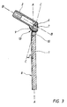
- the plate-screw implant (DHS) shown in FIG. 1 has a plate 1 which is screwed to the femur, the screws being passed through the openings 11 shown in FIG. 2.
- the screw 3 serves for stabilization, the threaded portion 4 of which is screwed into the femoral head and the thread-free shaft 5 is positively and thus non-rotatable, but axially slidable, guided in the leg tube 2.
- two fork legs 7 are formed at one end of the plate 1.
- An end section of the leg tube 2 extends between these fork legs 7.
- This end section of the leg tube 2 can be pivoted between these fork legs 7 about an axis 6 shown in FIG.
- pivot pins 12 are shown schematically which can be screwed into the fork legs 7 and which protrude into corresponding bearing bores in the leg tube 3.
- a tooth segment 9 is formed at the end section of the leg tube 3, the teeth 13 of which mesh with a worm 10 arranged in the plate 1 between the fork legs 7.
- a plug opening for a key is formed at the externally accessible end of the screw 10.
- the angle ⁇ between the center plane A-A of the plate 1 and the axis B-B of the leg tube 2 is set to the required value.
- the axes C-C of the fork legs 7 are inclined away from the bone contact side 8 of the plate 1 by the angle ⁇ , which is in the range from 10 ° to 12 °.
Landscapes
- Health & Medical Sciences (AREA)
- Orthopedic Medicine & Surgery (AREA)
- Surgery (AREA)
- Life Sciences & Earth Sciences (AREA)
- Heart & Thoracic Surgery (AREA)
- Nuclear Medicine, Radiotherapy & Molecular Imaging (AREA)
- Engineering & Computer Science (AREA)
- Biomedical Technology (AREA)
- Neurology (AREA)
- Medical Informatics (AREA)
- Molecular Biology (AREA)
- Animal Behavior & Ethology (AREA)
- General Health & Medical Sciences (AREA)
- Public Health (AREA)
- Veterinary Medicine (AREA)
- Prostheses (AREA)
- Surgical Instruments (AREA)
Claims (11)
- Implant à vis et à plaques, sur lequel est disposé sur la plaque pouvant être vissée au fémur un tube articulé recevant la section de la tige de vis sans filet de manière à ce qu'elle ne puisse pas être pivotée et de manière glissante, caractérisé en ce que pour le réglage de l'angle (α) entre la plaque (1) et le tube articulé (2), celui-ci est logé sur la plaque (1) de manière à pouvoir pivoter autour d'un axe (6) s'étendant parallèlement au plan médian de la plaque (A-A) et peut être basculé autour de l'axe (6) au moyen d'un engrenage de réglage formé comme engrenage à roue dentée accessible de l'extérieur et arrêté dans la position angulaire réglée.
- Implant selon la revendication 1, caractérisé en ce que l'angle (α) entre la plaque (1) et le tube articulé (2) est réglable dans une plage angulaire de 85° à 155°.
- Implant selon les revendications 1 ou 2, caractérisé en ce qu'un moyen immobilisateur ou de bloquage est prévu pour la position angulaire réglée.
- Implant selon au moins une des revendications 1 à 3, caractérisé en ce qu'à l'extrémité de la plaque (1) deux branches de fourche (7) sont formées sur lesquelles est monté le tube articulé (2) de manière à pouvoir pivoter.
- Implant selon la revendication 4, caractérisé en ce que les axes longitudinaux (C-C) des branches de fourche (7) sont inclinées en s'écartant du côté d'appui à l'os (8) de la plaque (1).
- Implant selon la revendication 5, caractérisé en ce que l'angle d'inclinaison (β) entre les axes longitudinaux (C-C) des branches de fourche (7) et du plan médian de la plaque (A-A) se situe dans la plage de 10° à 12°.
- Implant selon au moins une des revendications 4 à 6, caractérisé en ce que des tourillons sont formés dans les branches de fourche (7) sur lesquelles est monté le tube articulé (2) de manière à pouvoir pivoter.
- Implant selon au moins une des revendications 3 à 7, caractérisé en ce qu'à la section du tube articulé (2) s'étendant entre les branches de fourche (7) un segment denté (9) est disposé ou formé qui s'engrène avec une vis sans fin d'engrenage (10) qui est montée dans la partie transversale de la fourchette de la plaque (1) formée par les branches de fourche (7).
- Implant selon la revendication 8, caractérisé en ce que l'engrenage à vis sans fin formé par le segment denté (9) et la vis sans fin d'engrenage (10) est autobloquant.
- Implant selon les revendications 8 au 9, caractérisé en ce que sur l'extrémité accessible de l'extérieur de la vis sans fin d'engrenage un raccord pour clé à douille est formé.
- Implant selon l'une quelconque des revendications 7 à 10, caractérisé en ce que les tourillons peuvent être enfichés ou vissés dans les branches de fourche (7).
Applications Claiming Priority (3)
| Application Number | Priority Date | Filing Date | Title |
|---|---|---|---|
| DE4217236A DE4217236C2 (de) | 1992-05-20 | 1992-05-20 | Platten-Schrauben-Implantat |
| DE4217236 | 1992-05-20 | ||
| PCT/DE1993/000445 WO1993022982A1 (fr) | 1992-05-20 | 1993-05-17 | Implant a vis et a plaques |
Publications (2)
| Publication Number | Publication Date |
|---|---|
| EP0645985A1 EP0645985A1 (fr) | 1995-04-05 |
| EP0645985B1 true EP0645985B1 (fr) | 1997-10-15 |
Family
ID=6459664
Family Applications (1)
| Application Number | Title | Priority Date | Filing Date |
|---|---|---|---|
| EP93909784A Expired - Lifetime EP0645985B1 (fr) | 1992-05-20 | 1993-05-17 | Implant a vis et a plaques |
Country Status (5)
| Country | Link |
|---|---|
| EP (1) | EP0645985B1 (fr) |
| JP (1) | JPH07509621A (fr) |
| AT (1) | ATE159164T1 (fr) |
| DE (1) | DE4217236C2 (fr) |
| WO (1) | WO1993022982A1 (fr) |
Families Citing this family (22)
| Publication number | Priority date | Publication date | Assignee | Title |
|---|---|---|---|---|
| DE4438620A1 (de) * | 1994-05-02 | 1995-11-09 | Laghaollah Dr Elhami | Gelenkprothese und Vorrichtung zum Einbringen einer Bohrung in mindestens einen Gelenkkopf |
| EP0901625B1 (fr) * | 1996-05-14 | 2003-07-30 | Ufz-Umweltforschungszentrum Leipzig-Halle Gmbh | Procede et dispositifs pour caracteriser des points de mesure d'eaux souterraines par differenciation des eaux souterraines et des eaux dormantes |
| GB9613994D0 (en) * | 1996-07-04 | 1996-09-04 | Dall Vagn E | Hip compression screw assemblies and joints therefor |
| US7951176B2 (en) | 2003-05-30 | 2011-05-31 | Synthes Usa, Llc | Bone plate |
| CN1819799B (zh) | 2003-08-26 | 2010-05-26 | 斯恩蒂斯有限公司 | 骨板 |
| US11259851B2 (en) | 2003-08-26 | 2022-03-01 | DePuy Synthes Products, Inc. | Bone plate |
| US11291484B2 (en) | 2004-01-26 | 2022-04-05 | DePuy Synthes Products, Inc. | Highly-versatile variable-angle bone plate system |
| US8574268B2 (en) | 2004-01-26 | 2013-11-05 | DePuy Synthes Product, LLC | Highly-versatile variable-angle bone plate system |
| US7229445B2 (en) | 2004-06-21 | 2007-06-12 | Synthes (Usa) | Bone plate with bladed portion |
| ES2751997T3 (es) | 2008-01-14 | 2020-04-02 | Conventus Orthopaedics Inc | Aparato de reparación de fracturas |
| US8926611B2 (en) | 2009-09-14 | 2015-01-06 | Zimmer Gmbh | Angular lag implant for intramedullary nails |
| US8961518B2 (en) | 2010-01-20 | 2015-02-24 | Conventus Orthopaedics, Inc. | Apparatus and methods for bone access and cavity preparation |
| CN107569279A (zh) * | 2010-03-08 | 2018-01-12 | 康文图斯整形外科公司 | 用于骨修复的装置及方法 |
| JP6539652B2 (ja) | 2013-12-12 | 2019-07-03 | コンベンタス オーソピディックス, インコーポレイテッド | 組織変位ツールおよび方法 |
| US10624686B2 (en) | 2016-09-08 | 2020-04-21 | DePuy Synthes Products, Inc. | Variable angel bone plate |
| US10820930B2 (en) | 2016-09-08 | 2020-11-03 | DePuy Synthes Products, Inc. | Variable angle bone plate |
| US10905476B2 (en) | 2016-09-08 | 2021-02-02 | DePuy Synthes Products, Inc. | Variable angle bone plate |
| WO2019010252A2 (fr) | 2017-07-04 | 2019-01-10 | Conventus Orthopaedics, Inc. | Appareil et méthodes de traitement d'os |
| US11026727B2 (en) | 2018-03-20 | 2021-06-08 | DePuy Synthes Products, Inc. | Bone plate with form-fitting variable-angle locking hole |
| US10772665B2 (en) | 2018-03-29 | 2020-09-15 | DePuy Synthes Products, Inc. | Locking structures for affixing bone anchors to a bone plate, and related systems and methods |
| US11013541B2 (en) | 2018-04-30 | 2021-05-25 | DePuy Synthes Products, Inc. | Threaded locking structures for affixing bone anchors to a bone plate, and related systems and methods |
| US10925651B2 (en) | 2018-12-21 | 2021-02-23 | DePuy Synthes Products, Inc. | Implant having locking holes with collection cavity for shavings |
Family Cites Families (6)
| Publication number | Priority date | Publication date | Assignee | Title |
|---|---|---|---|---|
| US3256877A (en) * | 1961-12-11 | 1966-06-21 | Edward J Haboush | Adjustable nail plate joint |
| US3554193A (en) * | 1968-07-05 | 1971-01-12 | Ilias Konstantinou | Femur-setting surgical device |
| FR2554710B1 (fr) * | 1983-11-14 | 1987-09-25 | Medicalex | Materiel d'osteosynthese pour le traitement des fractures du femur |
| US4628923A (en) * | 1983-11-28 | 1986-12-16 | Medoff Robert J | Axial compression device |
| IT1232572B (it) * | 1989-02-10 | 1992-02-26 | Calderale Pasquale Mario | Mezzi di osteosintesi per il collegamento di segmenti di fratture ossee |
| US4922896A (en) * | 1989-05-05 | 1990-05-08 | John M. Agee | Colles' fracture splint |
-
1992
- 1992-05-20 DE DE4217236A patent/DE4217236C2/de not_active Expired - Lifetime
-
1993
- 1993-05-17 JP JP5519778A patent/JPH07509621A/ja active Pending
- 1993-05-17 WO PCT/DE1993/000445 patent/WO1993022982A1/fr active IP Right Grant
- 1993-05-17 AT AT93909784T patent/ATE159164T1/de not_active IP Right Cessation
- 1993-05-17 EP EP93909784A patent/EP0645985B1/fr not_active Expired - Lifetime
Also Published As
| Publication number | Publication date |
|---|---|
| DE4217236C2 (de) | 1996-10-31 |
| DE4217236A1 (de) | 1993-11-25 |
| WO1993022982A1 (fr) | 1993-11-25 |
| JPH07509621A (ja) | 1995-10-26 |
| EP0645985A1 (fr) | 1995-04-05 |
| ATE159164T1 (de) | 1997-11-15 |
Similar Documents
| Publication | Publication Date | Title |
|---|---|---|
| EP0645985B1 (fr) | Implant a vis et a plaques | |
| EP0699056B1 (fr) | Dispositif de fixation utilise en chirurgie osseuse | |
| DE3504495C2 (de) | Sacralfixierungsschraube und Sacralfixierungsvorrichtung | |
| EP0452451B1 (fr) | Vis pour pedicule vertebral et dispositif de correction et de maintien pourvu d'une telle vis | |
| AT389992B (de) | Vorrichtung zur externen fixierung von knochenfragmenten | |
| EP0570929B1 (fr) | Implant pour le rachis | |
| EP0636012B1 (fr) | Dispositif d'extension des os | |
| EP1273269B1 (fr) | Vis implantable pour stabiliser un assemblage articulé ou une fracture d'os | |
| EP0260222B1 (fr) | Ensemble d'implant pour ostéosynthèse | |
| EP0491138B1 (fr) | Dispositif de fixation d'os cassés | |
| EP1558159B1 (fr) | Dispositif permettant de traiter des fractures du femur | |
| EP0328883B1 (fr) | Dispositif d'étaiement de la colonne vertébrale humaine | |
| DE10259751B4 (de) | Vorrichtung zum Aufbringen einer ventral oder dorsal gerichteten Translationskraft im Kniegelenksbereich | |
| DE4007306C1 (en) | Implant for use in bone surgery - comprises two plates geared to allow relative external adjustment after fixture | |
| EP0791342A1 (fr) | Endoprothèse du col du fémur pour une articulation de hanche artificielle | |
| CH686339A5 (de) | Schraubenmutter fuer die Plattenosteosynthese. | |
| EP0173267A1 (fr) | Calibre de forage pour forer des trous de vis obliques au travers de trous de plaque dans des parties d'os à stabiliser | |
| EP0528177A2 (fr) | Fixateur externe pour la correction d'une spondylolisthésis lombaire | |
| DE102008045291A1 (de) | Kniearthrodese-Implantat | |
| DE3146065C2 (fr) | ||
| EP1416868B1 (fr) | Dispositif d'osteosynthese intramedullaire pour reparer des fractures laterales s'etendant vers le centre du femur | |
| EP1827267B1 (fr) | Dispositif de fixation orthopedique, et systeme de fixation orthopedique | |
| EP0456120B1 (fr) | Dispositif de transmission de puissance ou encore dispositif de fixation pour travaux d'ostéosynthèse | |
| WO1990012547A1 (fr) | Systeme de fixation pour fractures d'os tubulaires | |
| DE4002400A1 (de) | Verriegelungsnagel zur intramedullaeren anwendung bei der heilung von knochenbeschaedigungen |
Legal Events
| Date | Code | Title | Description |
|---|---|---|---|
| PUAI | Public reference made under article 153(3) epc to a published international application that has entered the european phase |
Free format text: ORIGINAL CODE: 0009012 |
|
| 17P | Request for examination filed |
Effective date: 19941210 |
|
| AK | Designated contracting states |
Kind code of ref document: A1 Designated state(s): AT CH LI |
|
| RAP1 | Party data changed (applicant data changed or rights of an application transferred) |
Owner name: STUCKENBROCK MEDIZINTECHNIK GMBH |
|
| GRAG | Despatch of communication of intention to grant |
Free format text: ORIGINAL CODE: EPIDOS AGRA |
|
| GRAH | Despatch of communication of intention to grant a patent |
Free format text: ORIGINAL CODE: EPIDOS IGRA |
|
| 17Q | First examination report despatched |
Effective date: 19970313 |
|
| GRAH | Despatch of communication of intention to grant a patent |
Free format text: ORIGINAL CODE: EPIDOS IGRA |
|
| GRAA | (expected) grant |
Free format text: ORIGINAL CODE: 0009210 |
|
| AK | Designated contracting states |
Kind code of ref document: B1 Designated state(s): AT CH LI |
|
| REF | Corresponds to: |
Ref document number: 159164 Country of ref document: AT Date of ref document: 19971115 Kind code of ref document: T |
|
| REG | Reference to a national code |
Ref country code: CH Ref legal event code: EP |
|
| REG | Reference to a national code |
Ref country code: CH Ref legal event code: NV Representative=s name: BOVARD AG PATENTANWAELTE |
|
| PG25 | Lapsed in a contracting state [announced via postgrant information from national office to epo] |
Ref country code: AT Free format text: LAPSE BECAUSE OF NON-PAYMENT OF DUE FEES Effective date: 19980517 |
|
| PLBE | No opposition filed within time limit |
Free format text: ORIGINAL CODE: 0009261 |
|
| STAA | Information on the status of an ep patent application or granted ep patent |
Free format text: STATUS: NO OPPOSITION FILED WITHIN TIME LIMIT |
|
| 26N | No opposition filed | ||
| REG | Reference to a national code |
Ref country code: CH Ref legal event code: PFA Owner name: STUCKENBROCK MEDIZINTECHNIK GMBH Free format text: STUCKENBROCK MEDIZINTECHNIK GMBH#LESSINGSTRASSE 50#78532 TUTTLINGEN (DE) -TRANSFER TO- STUCKENBROCK MEDIZINTECHNIK GMBH#LESSINGSTRASSE 50#78532 TUTTLINGEN (DE) |
|
| PGFP | Annual fee paid to national office [announced via postgrant information from national office to epo] |
Ref country code: CH Payment date: 20120530 Year of fee payment: 20 |
|
| REG | Reference to a national code |
Ref country code: CH Ref legal event code: PL |