EP0645985B1 - Platten-schrauben-implantat - Google Patents
Platten-schrauben-implantat Download PDFInfo
- Publication number
- EP0645985B1 EP0645985B1 EP93909784A EP93909784A EP0645985B1 EP 0645985 B1 EP0645985 B1 EP 0645985B1 EP 93909784 A EP93909784 A EP 93909784A EP 93909784 A EP93909784 A EP 93909784A EP 0645985 B1 EP0645985 B1 EP 0645985B1
- Authority
- EP
- European Patent Office
- Prior art keywords
- plate
- implant according
- prong
- arms
- articulated tube
- Prior art date
- Legal status (The legal status is an assumption and is not a legal conclusion. Google has not performed a legal analysis and makes no representation as to the accuracy of the status listed.)
- Expired - Lifetime
Links
- 239000007943 implant Substances 0.000 title claims abstract description 35
- 210000000689 upper leg Anatomy 0.000 claims abstract description 9
- 210000000988 bone and bone Anatomy 0.000 claims description 3
- 230000005540 biological transmission Effects 0.000 claims description 2
- 238000003780 insertion Methods 0.000 claims 1
- 230000037431 insertion Effects 0.000 claims 1
- 230000004048 modification Effects 0.000 abstract 1
- 238000012986 modification Methods 0.000 abstract 1
- 230000000087 stabilizing effect Effects 0.000 abstract 1
- 210000002414 leg Anatomy 0.000 description 38
- 230000007704 transition Effects 0.000 description 2
- 230000006978 adaptation Effects 0.000 description 1
- 230000037396 body weight Effects 0.000 description 1
- 210000002436 femur neck Anatomy 0.000 description 1
- 210000003739 neck Anatomy 0.000 description 1
- 230000006641 stabilisation Effects 0.000 description 1
- 238000011105 stabilization Methods 0.000 description 1
Images

Classifications
-
- A—HUMAN NECESSITIES
- A61—MEDICAL OR VETERINARY SCIENCE; HYGIENE
- A61B—DIAGNOSIS; SURGERY; IDENTIFICATION
- A61B17/00—Surgical instruments, devices or methods
- A61B17/56—Surgical instruments or methods for treatment of bones or joints; Devices specially adapted therefor
- A61B17/58—Surgical instruments or methods for treatment of bones or joints; Devices specially adapted therefor for osteosynthesis, e.g. bone plates, screws or setting implements
- A61B17/68—Internal fixation devices, including fasteners and spinal fixators, even if a part thereof projects from the skin
- A61B17/74—Devices for the head or neck or trochanter of the femur
- A61B17/742—Devices for the head or neck or trochanter of the femur having one or more longitudinal elements oriented along or parallel to the axis of the neck
- A61B17/748—Devices for the head or neck or trochanter of the femur having one or more longitudinal elements oriented along or parallel to the axis of the neck with means for adapting the angle between the longitudinal elements and the shaft axis of the femur
-
- A—HUMAN NECESSITIES
- A61—MEDICAL OR VETERINARY SCIENCE; HYGIENE
- A61B—DIAGNOSIS; SURGERY; IDENTIFICATION
- A61B17/00—Surgical instruments, devices or methods
- A61B17/56—Surgical instruments or methods for treatment of bones or joints; Devices specially adapted therefor
- A61B17/58—Surgical instruments or methods for treatment of bones or joints; Devices specially adapted therefor for osteosynthesis, e.g. bone plates, screws or setting implements
- A61B17/68—Internal fixation devices, including fasteners and spinal fixators, even if a part thereof projects from the skin
- A61B17/74—Devices for the head or neck or trochanter of the femur
- A61B17/742—Devices for the head or neck or trochanter of the femur having one or more longitudinal elements oriented along or parallel to the axis of the neck
- A61B17/746—Devices for the head or neck or trochanter of the femur having one or more longitudinal elements oriented along or parallel to the axis of the neck the longitudinal elements coupled to a plate opposite the femoral head
Definitions
- the invention relates to a plate screw implant according to the preamble of claim 1.
- Such implants are described in the book "The Dynamic Hip Screw Implant System" by P. Regazzoni, Th. Joedi, R. Winquist, M. Allgöwer, Springer Verlag and designated DHS and DCS.
- Such implants are primarily used for fractures between the femoral neck and the femoral shaft, i.e. in the pertrochanteric region.
- These implants not only enable a stable anatomical fixation at the fracture site, but also a guided pushing and compressing of the fracture surfaces through a load, because the screw, which is prevented from rotating, is slidably guided. This results in early mobilization of the patients, since these dynamic implants allow the fixed fracture to be loaded with full body weight, which is important for elderly patients, where these fractures are very common.
- the plate and leg tube are made in one piece. Since the CCD angle, i.e. the angles that the thigh necks form with the femoral shafts are different, implants with different angular positions must be provided between the thigh tube and the plate. Four different implants with angles of 135 °, 140 °, 145 ° and 150 ° are available for the hip area alone. In addition, various DCS must be made available for the corresponding CCD angle ranges. The practice of applying DHS and DCS requires different implants to be kept in stock. Since the available angles between the leg tube and the plate are stepped by 5 ° in practice, the surgeon can only achieve an approximate adaptation to anatomical conditions.
- intraoperative or subsequent valgization of the fracture is also desirable, especially to prevent harmful shear stresses.
- the invention has for its object to provide a dynamic plate screw implant, as described above, by which the previous variety of types is replaced and which enables the surgeon to continuously adapt to anatomical conditions and intraoperative or subsequent valgization.
- this object is achieved in that, in order to adjust the angle between the plate and the leg tube, the latter is rotatably mounted on the plate about an axis extending parallel to the plate center plane (AA) and can be pivoted about the axis and locked in the set angular position by means of an adjustment gear designed as an externally accessible gear transmission.
- the rotatable mounting is particularly advantageously designed in such a way that the angle between the plate and the leg tube can be set in an angle range from 85 ° to 155 °.
- Valgization can advantageously be carried out intraoperatively or subsequently, for example by means of a wedge osteotomy of the femur, since the angle between the plate and the leg tube can also be set to the desired value in the case of the implanted implant.
- a clamp or ratchet is advantageously provided.
- a locking device or locking device is used with particular advantage for locking.
- One of the locking elements is arranged on the plate and the other on the leg tube or on the axis of rotation of the leg tube.
- This adjustment is particularly advantageous for intraoperative or subsequent valgization.
- two fork legs are formed on one end of the plate, on which the leg tube is rotatably mounted.
- a section of the leg tube is located between the two fork legs.
- the implant in a DHS extends from the femur into the lower section of the trochanter, it should be possible to adapt it to the transition point from the femur to the trochanter.
- the longitudinal axes of the fork legs are advantageously inclined away from the bone contact side of the plate. It has proven to be advantageous that the angle of inclination between the longitudinal axes of these fork legs and the central plane of the plate is in the range from 10 ° to 12 °.
- bearing journals are formed in the fork legs, in which the leg tube is rotatably mounted.
- An advantageous and simple adjustment mechanism for adjusting the angle between the plate and the leg tube is formed in that a toothed segment is arranged or formed on the section of the leg tube extending between the fork legs, which meshes with a drive worm which in the web portion of the fork formed by the fork legs Plate is mounted.
- This worm drive formed by the toothed segment and the drive worm is designed so that it is self-locking Worm drive absorbs the normally occurring moments when the leg tube is loaded.
- a socket connection is particularly advantageously formed at the end of the drive worm that is accessible from the outside. This simplifies the setting of the angle between the leg tube and the plate.
- the trunnions can be inserted or screwed into the fork legs. It is only necessary to insert a leg tube equipped with appropriate counter bearings between the fork ends and then to mount the bearing pins in their engagement position in the legs.
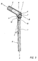
- the plate-screw implant (DHS) shown in FIG. 1 has a plate 1 which is screwed to the femur, the screws being passed through the openings 11 shown in FIG. 2.
- the screw 3 serves for stabilization, the threaded portion 4 of which is screwed into the femoral head and the thread-free shaft 5 is positively and thus non-rotatable, but axially slidable, guided in the leg tube 2.
- two fork legs 7 are formed at one end of the plate 1.
- An end section of the leg tube 2 extends between these fork legs 7.
- This end section of the leg tube 2 can be pivoted between these fork legs 7 about an axis 6 shown in FIG.
- pivot pins 12 are shown schematically which can be screwed into the fork legs 7 and which protrude into corresponding bearing bores in the leg tube 3.
- a tooth segment 9 is formed at the end section of the leg tube 3, the teeth 13 of which mesh with a worm 10 arranged in the plate 1 between the fork legs 7.
- a plug opening for a key is formed at the externally accessible end of the screw 10.
- the angle ⁇ between the center plane A-A of the plate 1 and the axis B-B of the leg tube 2 is set to the required value.
- the axes C-C of the fork legs 7 are inclined away from the bone contact side 8 of the plate 1 by the angle ⁇ , which is in the range from 10 ° to 12 °.
Landscapes
- Health & Medical Sciences (AREA)
- Orthopedic Medicine & Surgery (AREA)
- Surgery (AREA)
- Life Sciences & Earth Sciences (AREA)
- Heart & Thoracic Surgery (AREA)
- Nuclear Medicine, Radiotherapy & Molecular Imaging (AREA)
- Engineering & Computer Science (AREA)
- Biomedical Technology (AREA)
- Neurology (AREA)
- Medical Informatics (AREA)
- Molecular Biology (AREA)
- Animal Behavior & Ethology (AREA)
- General Health & Medical Sciences (AREA)
- Public Health (AREA)
- Veterinary Medicine (AREA)
- Prostheses (AREA)
- Surgical Instruments (AREA)
Description
- Die Erfindung bezieht sich auf ein Platten-Schrauben-Implantat nach dem Oberbegriff des Anspruchs 1.
- Derartige Implantate werden in dem Buch "The Dynamic Hip Screw Implant System" von P. Regazzoni, Th. Rüedi, R. Winquist, M. Allgöwer, Springer Verlag beschrieben und mit DHS und DCS bezeichnet. Derartige Implantate finden ihre Anwendung in erster Linie bei Brüchen zwischen Oberschenkelhals und Oberschenkelschaft, also in der pertrochantären Region. Diese Implantate ermöglichen nicht nur eine stabile anatomische Fixierung an der Bruchstelle, sondern auch ein geführtes Zusammenschieben und Zusammendrücken der Bruchflächen durch eine Belastung, weil die an einer Drehung verhinderte Schraube gleitbar geführt ist. Dies hat eine frühzeitige Mobilisierung der Patienten zur Folge, da diese dynamischen Implantate eine Belastung der fixierten Bruchstelle mit vollem Körpergewicht erlauben, was für ältere Patienten, bei denen diese Brüche sehr häufig vorkommen, von Bedeutung ist.
- Bei diesen bekannten Implantaten sind Platte und Schenkelrohr einteilig ausgebildet. Da die CCD-Winkel, d.h. die Winkel, die die Schenkelhälse mit den Femurschäften bilden, verschieden sind, müssen Implantate mit unterschiedlichen Winkelstellungen zwischen dem Schenkelrohr und der Platte vorgesehen sein. Allein für den Hüftbereich stehen vier verschiedene Implantate mit Winkeln von 135°, 140°, 145° und 150° zur Verfügung. Zusätzlich müssen verschiedene DCS für entsprechende CCD-Winkelbereiche zur Verfügung gestellt werden. Die Praxis der Applikation von DHS und DCS erfordert eine Vorratshaltung unterschiedlicher Implantate. Da die zur Verfügung stehenden Winkel zwischen dem Schenkelrohr und der Platte in der Praxis um 5° abgestuft sind, kann der Chirurg lediglich eine approximative Anpassung an anatomische Gegebenheiten erzielen.
- In vielen Fällen ist ferner eine intraoperative oder nachträgliche Valgisation der Fraktur, insbesondere zur Verhinderung schädlicher Scherbelastungen wünschenswert.
- Der Erfindung liegt die Aufgabe zugrunde, ein dynamisches Platten-Schrauben-Implantat, wie vorstehend beschrieben, zur Verfügung zu stellen, durch das die bisherige Typenvielfalt ersetzt wird und das dem Chirurgen eine stufenlose Anpassung an anatomische Gegebenheiten sowie eine intraoperative oder nachträgliche Valgisation ermöglicht.
- Erfindungsgemäß wird diese Aufgabe dadurch gelöst, daß zur Einstellung des Winkels zwischen der Platte und dem Schenkelrohr dieses an der Platte um eine parallel sich zur Plattenmittelebene (A-A) erstreckende Achse drehbar gelagert und mittels eines als von außen zugängiges Zahnradgetriebe ausgebildetes Verstellgetriebe um die Achse verschwenkbar und in der eingestellten Winkellage arretierbar ist. Mit besonderem Vorteil ist die drehbare Lagerung derart gestaltet, daß der Winkel zwischen der Platte und dem Schenkelrohr in einem Winkelbereich von 85° bis 155° einstellbar ist.
- Zur Versorgung der Patienten mit unterschiedlich gelagerten Brüchen ist es lediglich erforderlich, einen einzigen Platten-Schrauben-Implantattyp zur Verfügung zu haben. Der Chirurg kann dieses Implantat stufenlos an die anatomischen Gegebenheiten des Patienten anpassen. Dadurch, daß die eingestellte Winkellage arretierbar, das heißt festlegbar, ist, werden vom Implantat in sicherer Weise die auftretenden Momente bei Belastung aufgenommen.
- Mit Vorteil kann intraoperativ oder nachträglich eine Valgisation, beispielsweise mittels einer Keilosteotomie des Femur durchgeführt werden, da der Winkel zwischen der Platte und dem Schenkelrohr auch beim implantierten Implantat auf den gewünschten Wert eingestellt werden kann.
- Zur Arretierung des Schenkelrohrs in der eingestellten Winkellage wird mit Vorteil ein Gehemme oder Gesperre vorgesehen. Mit besonderem Vorteil wird zur Arretierung ein Formgehemme oder Formgesperre verwendet. Dabei ist eines der Gesperreelemente an der Platte und das andere am Schenkelrohr oder an der Drehachse des Schenkelrohres angeordnet.
- Diese Verstellung ist insbesondere für die intraoperative oder nachträgliche Valgisation von Vorteil.
- Bei einer vorteilhaften Ausführungsform des Erfindungsgegenstandes sind an einem Ende der Platte zwei Gabelschenkel ausgebildet, an denen das Schenkelrohr drehbar gelagert ist. Dabei befindet sich ein Abschnitt des Schenkelrohres zwischen den beiden Gabelschenkeln.
- Da sich bei einer DHS das Implantat vom Femur in den unteren Abschnitt des Trochanters hineinerstreckt, sollte eine Anpassung an die Übergangsstelle vom Femur in den Trochanter möglich sein. In vorteilhafter Weise sind zu diesem Zweck die Längsachsen der Gabelschenkel von der Knochenanlageseite der Platte fortgeneigt. Es hat sich als vorteilhaft erwiesen, daß der Neigungswinkel zwischen den Längsachsen dieser Gabelschenkel und der Plattenmittelebene im Bereich von 10° bis 12° liegt.
- Bei einer weiteren vorteilhaften Ausführungsform des erfindungsgemäßen Implantats sind in den Gabelschenkeln Lagerzapfen ausgebildet, in denen das Schenkelrohr drehbar gelagert ist.
- Ein vorteilhaftes und einfaches Verstellgetriebe zur Einstellung des Winkels zwischen Platte und Schenkelrohr wird dadurch gebildet, daß am zwischen den Gabelschenkeln sich erstreckenden Abschnitt des Schenkelrohrs ein Zahnsegment angeordnet oder ausgebildet ist, welches mit einer Antriebsschnecke kämmt, die im Stegabschnitt der von den Gabelschenkeln gebildeteten Gabel der Platte montiert ist. Dieser vom Zahnsegment und der Antriebsschnecke gebildete Schneckenantrieb ist derart selbsthemmend ausgelegt, daß dieser Schneckenantrieb die normalerweise auftretenden Momente bei einer Belastung des Schenkelrohrs aufnimmt. Mit besonderem Vorteil ist am vom außen zugänglichen Ende der Antriebsschnecke ein Steckschlüsselanschluß ausgebildet. Hierdurch wird die Einstellung des Winkels zwischen Schenkelrohr und Platte vereinfacht.
- Um die Montage zu vereinfachen, sind die Lagerzapfen in die Gabelschenkel einsteck- oder einschraubbar. Es ist lediglich erforderlich, ein mit entsprechenden Gegenlagern ausgerüstetes Schenkelrohr zwischen die Gabelenden einzusetzen und dann die Lagerzapfen in ihrer Eingriffslage in den Schenkeln anzubringen.
- Ein Ausführungsbeispiel der Erfindung soll unter Bezugnahme auf die Figuren der Zeichnung in der folgenden Beschreibung erläutert werden. Es zeigen:
- Fig. 1
- eine schematische Seitenansicht eines als DHS-dynamische Hüftschraube bezeichneten Implantats,
- Fig. 2
- eine Ansicht des in Figur 1 dargestellten Implantates von rechts gesehen und
- Fig. 3
- eine schematische Schnittansicht des Implantates ohne Schraube.
- Das in Fig. 1 dargestellte Platten-Schrauben-Implantat (DHS) weist eine Platte 1 auf, die am Femur verschraubt wird, wobei die Schrauben durch die in Figur 2 dargestellten Öffnungen 11 hindurchgeführt werden. Zur Stabilisierung dient die Schraube 3, deren Gewindeabschnitt 4 in den Hüftkopf eingeschraubt wird und deren gewindefreier Schaft 5 formschlüssig und somit unverdrehbar, jedoch axial gleitbar, im Schenkelrohr 2 geführt ist.
- Wie insbesondere Figur 2 zeigt, sind an einem Ende der Platte 1 zwei Gabelschenkel 7 ausgebildet. Zwischen diese Gabelschenkel 7 erstreckt sich ein Endabschnitt des Schenkelrohres 2. Dieser Endabschnitt des Schenkelrohres 2 ist zwischen diesen Gabelschenkeln 7 um eine in Figur 2 dargestellte Achse 6 verschwenkbar. Durch diese Verschwenkung kann der in Figur 1 dargestellte Winkel α zwischen dem Schenkelrohr 2 und damit der Schraube 3 einerseits und der Platte 1 andererseits eingestellt werden. In Figur 1 sind schematisch in die Gabelschenkel 7 einschraubbare Drehzapfen 12 dargestellt, die in entsprechende Lagerbohrungen im Schenkelrohr 3 hineinragen.
- Wie die Figuren 1-3 zeigen, ist am Endabschnitt des Schenkelrohres 3 ein Zahnsegment 9 ausgebildet, dessen Zähne 13 mit einer in der Platte 1 zwischen den Gabelschenkeln 7 angeordneten Schnecke 10 kämmt. Am von außen zugänglichen Ende der Schnecke 10 ist eine Stecköffnung für einen Schlüssel ausgebildet.
- Durch eine Betätigung der Schnecke 10 wird der Winkel α zwischen der Mittelebene A-A der Platte 1 und der Achse B-B des Schenkelrohrs 2 auf den erforderlichen Wert eingestellt.
- Zur Anpassung des Implantats an die Übergangsstelle zwischen Femur und Trochanter sind die Achsen C-C der Gabelschenkel 7 von der Knochenanlageseite 8 der Platte 1 um den Winkel β fortgeneigt, der im Bereich von 10° bis 12° liegt.
Claims (11)
- Platten-Schrauben-Implantat, an dessen am Femur verschraubbare Platte ein den gewindefreien Schaftabschnitt der Schraube unverdrehbar und gleitbar aufnehmendes Schenkelrohr angeordnet ist, dadurch gekennzeichnet, daß zur Einstellung des Winkels (α) zwischen der Platte (1) und dem Schenkelrohr (2) dieses an der Platte (1) um eine parallel sich zur Plattenmittelebene (A-A) erstreckende Achse (6) drehbar gelagert und mittels eines als von außen zugängiges Zahnradgetriebe ausgebildetes Verstellgetriebe um die Achse (6) verschwenkbar und in der eingestellten Winkellage arretierbar ist.
- Implantat nach Anspruch 1, dadurch gekennzeichnet, daß der Winkel (α) zwischen der Platte (1) und dem Schenkelrohr (2) in einem Winkelbereich von 85° - 155° einstellbar ist.
- Implantat nach Anspruch 1 oder 2, dadurch gekennzeichnet, daß zur Arretierung des Schenkelrohres (2) in der eingestellten Winkellage ein Gehemme oder Gesperre vorgesehen ist.
- Implantat nach mindestens einem der Ansprüche 1-4, dadurch gekennzeichnet, daß an einem Ende der Platte (1) zwei Gabelschenkel (7) ausgebildet sind, an denen das Schenkelrohr (2) drehbar gelagert ist.
- Implantat nach Anspruch 5, dadurch gekennzeichnet, daß die Längsachsen (C-C) der Gabelschenkel (7) von der Knochenanlageseite (8) der Platte (1) fortgeneigt sind.
- Implantat nach Anspruch 6, dadurch gekennzeichnet, daß der Neigungswinkel (β) zwischen den Längsachsen (C-C) der Gabelschenkel (7) und der Plattenmittelebene (A-A) im Bereich von 10°-12° liegt.
- Implantat nach mindestens einem der Ansprüche 5-7, dadurch gekennzeichnet, daß in den Gabelschenkeln (7) Lagerzapfen ausgebildet sind, an denen das Schenkelrohr (2) drehbar gelagert ist.
- Implantat nach mindestens einem der Ansprüche 4-8, dadurch gekennzeichnet, daß am zwischen den Gabelschenkeln (7) sich erstreckenden Abschnitt des Schenkelrohres (2) ein Zahnsegment (9) angeordnet oder ausgebildet ist, welches mit einer Antriebsschnecke (10) kämmt, die im Stegabschnitt der von den Gabelschenkeln (7) gebildeten Gabel der Platte (1) montiert ist.
- Implantat nach Anspruch 9, dadurch gekennzeichnet, daß der vom Zahnsegment (9) und der Antriebsschnecke (10) gebildete Schneckenantrieb selbsthemmend ausgelegt ist.
- Implantat nach Anspruch 9 oder 10, dadurch gekennzeichnet, daß am von außen zugänglichen Ende der Antriebsschnecke ein Steckschlüsselanschluß ausgebildet ist.
- Implantat nach einem der Ansprüche 8-11, dadurch gekennzeichnet, daß die Lagerzapfen in die Gabelschenkel (7) einsteck- oder einschraubbar sind.
Applications Claiming Priority (3)
| Application Number | Priority Date | Filing Date | Title |
|---|---|---|---|
| DE4217236A DE4217236C2 (de) | 1992-05-20 | 1992-05-20 | Platten-Schrauben-Implantat |
| DE4217236 | 1992-05-20 | ||
| PCT/DE1993/000445 WO1993022982A1 (de) | 1992-05-20 | 1993-05-17 | Platten-schrauben-implantat |
Publications (2)
| Publication Number | Publication Date |
|---|---|
| EP0645985A1 EP0645985A1 (de) | 1995-04-05 |
| EP0645985B1 true EP0645985B1 (de) | 1997-10-15 |
Family
ID=6459664
Family Applications (1)
| Application Number | Title | Priority Date | Filing Date |
|---|---|---|---|
| EP93909784A Expired - Lifetime EP0645985B1 (de) | 1992-05-20 | 1993-05-17 | Platten-schrauben-implantat |
Country Status (5)
| Country | Link |
|---|---|
| EP (1) | EP0645985B1 (de) |
| JP (1) | JPH07509621A (de) |
| AT (1) | ATE159164T1 (de) |
| DE (1) | DE4217236C2 (de) |
| WO (1) | WO1993022982A1 (de) |
Families Citing this family (23)
| Publication number | Priority date | Publication date | Assignee | Title |
|---|---|---|---|---|
| DE4438620A1 (de) * | 1994-05-02 | 1995-11-09 | Laghaollah Dr Elhami | Gelenkprothese und Vorrichtung zum Einbringen einer Bohrung in mindestens einen Gelenkkopf |
| WO1997043637A1 (de) * | 1996-05-14 | 1997-11-20 | Ufz-Umweltforschungszentrum Leipzig-Halle Gmbh | Verfahren und vorrichtungen zur charakterisierung von grundwassermessstellen durch unterscheidung von grundwasser und standwasser |
| GB9613994D0 (en) * | 1996-07-04 | 1996-09-04 | Dall Vagn E | Hip compression screw assemblies and joints therefor |
| US7951176B2 (en) | 2003-05-30 | 2011-05-31 | Synthes Usa, Llc | Bone plate |
| DE20321551U1 (de) | 2003-08-26 | 2007-12-27 | Synthes Gmbh | Knochenplatte |
| US11259851B2 (en) | 2003-08-26 | 2022-03-01 | DePuy Synthes Products, Inc. | Bone plate |
| US11291484B2 (en) | 2004-01-26 | 2022-04-05 | DePuy Synthes Products, Inc. | Highly-versatile variable-angle bone plate system |
| US8574268B2 (en) | 2004-01-26 | 2013-11-05 | DePuy Synthes Product, LLC | Highly-versatile variable-angle bone plate system |
| US7229445B2 (en) | 2004-06-21 | 2007-06-12 | Synthes (Usa) | Bone plate with bladed portion |
| EP2249718B1 (de) | 2008-01-14 | 2019-09-18 | Conventus Orthopaedics, Inc. | Gerät zur reparatur von frakturen |
| US8926611B2 (en) | 2009-09-14 | 2015-01-06 | Zimmer Gmbh | Angular lag implant for intramedullary nails |
| CN102821707B (zh) | 2010-01-20 | 2016-02-03 | 康文图斯整形外科公司 | 用于骨接近和骨腔准备的装置及方法 |
| CN108125714A (zh) * | 2010-03-08 | 2018-06-08 | 康文图斯整形外科公司 | 用于固定骨植入物的装置及方法 |
| CA2969316A1 (en) | 2013-12-12 | 2015-06-18 | Conventus Orthopaedics, Inc. | Tissue displacement tools and methods |
| US10820930B2 (en) | 2016-09-08 | 2020-11-03 | DePuy Synthes Products, Inc. | Variable angle bone plate |
| US10905476B2 (en) | 2016-09-08 | 2021-02-02 | DePuy Synthes Products, Inc. | Variable angle bone plate |
| US10624686B2 (en) | 2016-09-08 | 2020-04-21 | DePuy Synthes Products, Inc. | Variable angel bone plate |
| WO2019010252A2 (en) | 2017-07-04 | 2019-01-10 | Conventus Orthopaedics, Inc. | Apparatus and methods for treatment of a bone |
| US11026727B2 (en) | 2018-03-20 | 2021-06-08 | DePuy Synthes Products, Inc. | Bone plate with form-fitting variable-angle locking hole |
| US10772665B2 (en) | 2018-03-29 | 2020-09-15 | DePuy Synthes Products, Inc. | Locking structures for affixing bone anchors to a bone plate, and related systems and methods |
| US11013541B2 (en) | 2018-04-30 | 2021-05-25 | DePuy Synthes Products, Inc. | Threaded locking structures for affixing bone anchors to a bone plate, and related systems and methods |
| US10925651B2 (en) | 2018-12-21 | 2021-02-23 | DePuy Synthes Products, Inc. | Implant having locking holes with collection cavity for shavings |
| US12035928B2 (en) | 2021-11-12 | 2024-07-16 | NextWave Medical, LLC | Devices and methods for correction of hip deformities |
Family Cites Families (6)
| Publication number | Priority date | Publication date | Assignee | Title |
|---|---|---|---|---|
| US3256877A (en) * | 1961-12-11 | 1966-06-21 | Edward J Haboush | Adjustable nail plate joint |
| US3554193A (en) * | 1968-07-05 | 1971-01-12 | Ilias Konstantinou | Femur-setting surgical device |
| FR2554710B1 (fr) * | 1983-11-14 | 1987-09-25 | Medicalex | Materiel d'osteosynthese pour le traitement des fractures du femur |
| US4628923A (en) * | 1983-11-28 | 1986-12-16 | Medoff Robert J | Axial compression device |
| IT1232572B (it) * | 1989-02-10 | 1992-02-26 | Calderale Pasquale Mario | Mezzi di osteosintesi per il collegamento di segmenti di fratture ossee |
| US4922896A (en) * | 1989-05-05 | 1990-05-08 | John M. Agee | Colles' fracture splint |
-
1992
- 1992-05-20 DE DE4217236A patent/DE4217236C2/de not_active Expired - Lifetime
-
1993
- 1993-05-17 EP EP93909784A patent/EP0645985B1/de not_active Expired - Lifetime
- 1993-05-17 AT AT93909784T patent/ATE159164T1/de not_active IP Right Cessation
- 1993-05-17 WO PCT/DE1993/000445 patent/WO1993022982A1/de not_active Ceased
- 1993-05-17 JP JP5519778A patent/JPH07509621A/ja active Pending
Also Published As
| Publication number | Publication date |
|---|---|
| ATE159164T1 (de) | 1997-11-15 |
| DE4217236C2 (de) | 1996-10-31 |
| DE4217236A1 (de) | 1993-11-25 |
| EP0645985A1 (de) | 1995-04-05 |
| WO1993022982A1 (de) | 1993-11-25 |
| JPH07509621A (ja) | 1995-10-26 |
Similar Documents
| Publication | Publication Date | Title |
|---|---|---|
| EP0645985B1 (de) | Platten-schrauben-implantat | |
| EP0699056B1 (de) | Knochenchirurgische haltevorrichtung | |
| DE3504495C2 (de) | Sacralfixierungsschraube und Sacralfixierungsvorrichtung | |
| EP0452451B1 (de) | Pedikelschraube und korrektur- und haltevorrichtung mit einer solchen pedikelschraube | |
| DE3650528T2 (de) | Axialkompressionsvorrichtung | |
| AT389992B (de) | Vorrichtung zur externen fixierung von knochenfragmenten | |
| DE69519732T2 (de) | Knochenschraube mit reversibler Verschluss | |
| DE60108662T2 (de) | Verbindungsvorrichtung für variable winkel in einem spinalimplantatsystem | |
| EP0570929B1 (de) | Implantat für die Wirbeläule | |
| DE69319375T2 (de) | Wirbelprothese zum Ersetzen eines Wirbels in der Chirurgie maligner Tumore | |
| DE69012012T2 (de) | Stützvorrichtung für die wirbelsäule. | |
| EP0636012B1 (de) | Vorrichtung zur verlängerung von knochen | |
| DE2515430C2 (de) | Orthopädisches Gerät | |
| DE69510516T2 (de) | Osteosynthetisches Gerät zur Befestigung und/oder longitudinalen Ausrichtung | |
| EP0328883B1 (de) | Stützvorrichtung für die menschliche Wirbelsäule | |
| DE10259751B4 (de) | Vorrichtung zum Aufbringen einer ventral oder dorsal gerichteten Translationskraft im Kniegelenksbereich | |
| DE4007306C1 (en) | Implant for use in bone surgery - comprises two plates geared to allow relative external adjustment after fixture | |
| EP0791342A1 (de) | Schenkelhalsendoprothese für ein künstliches Hüftgelenk | |
| CH682300A5 (de) | ||
| CH686339A5 (de) | Schraubenmutter fuer die Plattenosteosynthese. | |
| WO2004039270A1 (de) | Vorrichtung zur behandlung von frakturen des femur | |
| EP1416868B1 (de) | Intramedulläre osteosyntheseeinrichtung zur versorgung von lateralen und nach medial reichenden femurfrakturen | |
| DE20007908U1 (de) | Konturierte Knochenplatte | |
| EP0456120B1 (de) | Kraftübertragungsvorrichtung bzw. Fixationsvorrichtung für osteosynthetische Arbeiten | |
| DE69332170T2 (de) | Gerät zur behandlung von thoraxdeformierungen wie skoliose |
Legal Events
| Date | Code | Title | Description |
|---|---|---|---|
| PUAI | Public reference made under article 153(3) epc to a published international application that has entered the european phase |
Free format text: ORIGINAL CODE: 0009012 |
|
| 17P | Request for examination filed |
Effective date: 19941210 |
|
| AK | Designated contracting states |
Kind code of ref document: A1 Designated state(s): AT CH LI |
|
| RAP1 | Party data changed (applicant data changed or rights of an application transferred) |
Owner name: STUCKENBROCK MEDIZINTECHNIK GMBH |
|
| GRAG | Despatch of communication of intention to grant |
Free format text: ORIGINAL CODE: EPIDOS AGRA |
|
| GRAH | Despatch of communication of intention to grant a patent |
Free format text: ORIGINAL CODE: EPIDOS IGRA |
|
| 17Q | First examination report despatched |
Effective date: 19970313 |
|
| GRAH | Despatch of communication of intention to grant a patent |
Free format text: ORIGINAL CODE: EPIDOS IGRA |
|
| GRAA | (expected) grant |
Free format text: ORIGINAL CODE: 0009210 |
|
| AK | Designated contracting states |
Kind code of ref document: B1 Designated state(s): AT CH LI |
|
| REF | Corresponds to: |
Ref document number: 159164 Country of ref document: AT Date of ref document: 19971115 Kind code of ref document: T |
|
| REG | Reference to a national code |
Ref country code: CH Ref legal event code: EP |
|
| REG | Reference to a national code |
Ref country code: CH Ref legal event code: NV Representative=s name: BOVARD AG PATENTANWAELTE |
|
| PG25 | Lapsed in a contracting state [announced via postgrant information from national office to epo] |
Ref country code: AT Free format text: LAPSE BECAUSE OF NON-PAYMENT OF DUE FEES Effective date: 19980517 |
|
| PLBE | No opposition filed within time limit |
Free format text: ORIGINAL CODE: 0009261 |
|
| STAA | Information on the status of an ep patent application or granted ep patent |
Free format text: STATUS: NO OPPOSITION FILED WITHIN TIME LIMIT |
|
| 26N | No opposition filed | ||
| REG | Reference to a national code |
Ref country code: CH Ref legal event code: PFA Owner name: STUCKENBROCK MEDIZINTECHNIK GMBH Free format text: STUCKENBROCK MEDIZINTECHNIK GMBH#LESSINGSTRASSE 50#78532 TUTTLINGEN (DE) -TRANSFER TO- STUCKENBROCK MEDIZINTECHNIK GMBH#LESSINGSTRASSE 50#78532 TUTTLINGEN (DE) |
|
| PGFP | Annual fee paid to national office [announced via postgrant information from national office to epo] |
Ref country code: CH Payment date: 20120530 Year of fee payment: 20 |
|
| REG | Reference to a national code |
Ref country code: CH Ref legal event code: PL |