EP0645163A1 - Ventil für Atmungsgerät - Google Patents
Ventil für Atmungsgerät Download PDFInfo
- Publication number
- EP0645163A1 EP0645163A1 EP94306766A EP94306766A EP0645163A1 EP 0645163 A1 EP0645163 A1 EP 0645163A1 EP 94306766 A EP94306766 A EP 94306766A EP 94306766 A EP94306766 A EP 94306766A EP 0645163 A1 EP0645163 A1 EP 0645163A1
- Authority
- EP
- European Patent Office
- Prior art keywords
- valve
- chamber
- valve member
- pressure
- outlet
- Prior art date
- Legal status (The legal status is an assumption and is not a legal conclusion. Google has not performed a legal analysis and makes no representation as to the accuracy of the status listed.)
- Granted
Links
Images


Classifications
-
- A—HUMAN NECESSITIES
- A62—LIFE-SAVING; FIRE-FIGHTING
- A62B—DEVICES, APPARATUS OR METHODS FOR LIFE-SAVING
- A62B9/00—Component parts for respiratory or breathing apparatus
- A62B9/02—Valves
- A62B9/022—Breathing demand regulators
-
- B—PERFORMING OPERATIONS; TRANSPORTING
- B63—SHIPS OR OTHER WATERBORNE VESSELS; RELATED EQUIPMENT
- B63C—LAUNCHING, HAULING-OUT, OR DRY-DOCKING OF VESSELS; LIFE-SAVING IN WATER; EQUIPMENT FOR DWELLING OR WORKING UNDER WATER; MEANS FOR SALVAGING OR SEARCHING FOR UNDERWATER OBJECTS
- B63C11/00—Equipment for dwelling or working underwater; Means for searching for underwater objects
- B63C11/02—Divers' equipment
- B63C11/18—Air supply
- B63C11/22—Air supply carried by diver
- B63C11/2227—Second-stage regulators
Definitions
- the present invention relates to gas flow control valves and more particularly to demand valves for breathing apparatus.
- the invention is concerned with a valve incorporating a so-called “balanced piston” valve member, which is characterised by low operating forces and an ability to operate consistently over a range of supply pressures.
- a valve for use in underwater diving equipment is described and illustrated schematically in United States patent specification no. 3647175. It is an aim of the present invention to adapt this principle to use in a positive pressure demand valve of compact construction and efficient operation.
- a gas flow control valve comprising: an inlet chamber and an outlet chamber; a movable valve member for controlling the flow of pressurised gas from the inlet chamber to the outlet chamber; and a flexible pressure-responsive member sensitive to the gas pressure within the outlet chamber for controlling the movement of the valve member;
- the valve member being an axially-slidable member of tubular form, one end of which extends into the inlet chamber, the other end of which leads to the outlet chamber, and the interior of which defines a flow path to lead gas from the inlet chamber to the outlet chamber; a valve seat facing the valve member in the inlet chamber such that the spacing of the valve member from said seat controls the rate of gas flow through the valve member from the inlet chamber to the outlet chamber and contact of the valve member with said seat shuts off such flow; spring means acting upon the valve member to bias the same away from said seat; the axis of flexure of the pressure-responsive member being inclined to the axis of the valve member and mechanical linkage means being provided to link the pressure
- the illustrated valve is for regulating the flow from a source of compressed air (not shown) into a facemask (not shown) worn by the user, at a variable rate sufficient to meet the breathing demand of the user and so as normally to maintain a specified super-ambient pressure within the facemask throughout the respiratory cycle.
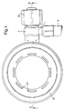
- a flexible hose H ( Figure 1) from the air source is connected to the inlet spigot 1 of a swivel connector 2 which leads, through radial ports 3 ( Figure 2), into a chamber 4 within a body member 5.
- valve member 6 communicates with a diaphragm chamber 14 and with the outlet 15 of the valve which in use is coupled into the inlet of the user's facemask. That end of the valve member is also mechanically coupled, through a two-armed wire link 16 and a flat, hook-shaped link 17, to one end of a coiled tension spring 18, the other end of which is anchored to a fixed post 19.
- the assembly of spring 18 and links 16,17 extends diametrally across the chamber 14 and coaxial with the valve member 6, the action of the spring being to bias the valve member in the direction away from its seat 8.
- a flowpath will therefore be formed from chamber 4, through the interior of the valve member 6, into chamber 14 and out through the outlet 15, the rate of flow at any time being determined by the spacing of the end of the valve member from its seat 8 and of course being shut off in the event that the valve member is moved into contact with the seat.
- a flexible diaphragm 20 Bounding the side of chamber 14 opposite to the outlet 15 is a flexible diaphragm 20 of e.g. silicone rubber. This diaphragm is clamped peripherally between housing members 21 and 22 of the valve structure and its central, flat portion is bonded to a rigid plate 23.
- the plate 23 carries a bridge piece 24 by which is trapped one end of a two-armed wire lever 25.
- the opposite ends of the lever's arms are turned in (as shown at 25A in Figure 3)and pivoted where indicated at 26 in the housing member 21, with the lever straddling the valve member 6.
- the inner side of the diaphragm 20 is exposed to the air pressure within chamber 14 (which is substantially the same as in the user's facemask) while the outer side of the diaphragm is exposed to ambient pressure (for which purpose the housing member 22 is ventilated with a ring of slots 27).
- the diaphragm will accordingly flex inwardly and outwardly in accordance with variations in the pressure differential across it. That is say, a reduction in the pressure within chamber 14 consequent upon inhalation of the user will draw the diaphragm 20 inwards allowing the valve member 6 to open (or open further) under the bias of spring 18 and supply air to the user in accordance with his breathing demand.
- the facemask will be equipped with a separate one-way exhalation valve (set at a higher opening pressure than the closing pressure of the demand valve) through which the user's exhalate is vented and which ensures that a fresh supply of air is provided by the demand valve to the user upon each inhalation.
- a separate one-way exhalation valve set at a higher opening pressure than the closing pressure of the demand valve
- the user of a demand valve has the option of bypassing the operation of the usual automatic control means in the event of some failure in the latter which results in an insufficient rate of flow being supplied by the valve or of the valve member even becoming stuck in its closed position. It is also desirable, particularly in the case of the illustrated valve where the supply pressure has no tendency to unseat the valve member 6, that means are provided for venting excess pressure in the event that an abnormally high supply pressure is experienced which might otherwise lead to a danger of bursting the supply hose H. In the illustrated valve the latter function is accomplished by the piston 13 to which the supply pressure is communicated from the chamber 4 by ports 10 around the valve seat 8.
- a strong spring 28 compressed between this piston and a sleeve 29 on the end of the body member 5 normally keeps the piston in its illustrated closed position against the "reverse" side of the seat 8. If the supplied pressure force exceeds the spring force on the piston 13, however, it will be displaced from the seat 8 and open a flow path from the ports 10 around the reverse side of the seat 8 and through its central port 9, thereby venting the excess pressure through the main valve into the facemask (and thence to atmosphere through the exhalation valve or around the face seal).
- the sleeve 29 is formed at two diametrically opposite positions with cam surfaces 30 each engageable with a respective peg 31 on the fixed body member 5.
- a knob 32 is keyed to the sleeve 29 for turning the same and is formed internally with cam surfaces 33 facing the surfaces 30 so as collectively to define a pair of helical slots.
- the rotational position of the sleeve 29 on the body member 5 is defined by detent recesses 34 adjacent to the cam surfaces 30 engaging the pegs 31, the sleeve being urged against the pegs 31 in this position by the action of the spring 28.
- a quarter anti-clockwise turn of the knob 32 causes the sleeve 29 to turn likewise with the helical slots defined between faces 30/33 running over the pegs 31 so that the sleeve and knob are also displaced axially away from the body member 5 by a distance determined by the pitch of those slots. In so doing the knob 32 engages a retainer 35 on the end of the piston 13 to withdraw the piston from the seat 8 and open the bypass flowpath.
- a positive pressure demand valve is a so-called "first breath” mechanism.
- first breath Another desirable feature of a positive pressure demand valve.
- the user of a breathing apparatus after donning the apparatus, turning on the gas supply and checking the operation of the apparatus, has to stand by for a period before entering the hazardous zone in which respiratory protection is required.
- the user of a breathing apparatus after donning the apparatus, turning on the gas supply and checking the operation of the apparatus, has to stand by for a period before entering the hazardous zone in which respiratory protection is required.
- the demand valve For personal comfort and to avoid unnecessary depletion of the gas source it is usual to doff the facemask during such periods, or disconnect the demand valve from the facemask and breath ambient air through the mask inlet.
- the pressure sensed within the demand valve is now only ambient, its normal reaction is to open fully under its positive pressure bias (i.e.
- a slide 36 manually-accessible at 36A, is borne in the side of the valve outlet 15 and biased outwards by a compression spring 37.
- the inner end of the slide 36 carries a flanged button 38 which faces the head 17A of the hook-shaped plate 17 below its connection to the spring 18.
- a light compression spring 39 is also trapped between the head 17A of the plate and the end of the link 16 coupled to that plate. The effect of pressing in the slide 36, therefore, is to push the plate 17 to the right (as viewed in Figure 2) and this has the effect of seating the valve member 6, thereby shutting off the flow of gas through the valve.
- the slide 36 also serves the function of locking the demand valve into the inlet of the user's facemask.
- the outlet 15 of the demand valve is formed as a bayonet connector, with a pair of circumferential ledges 42 projecting at two diametrically opposite locations.
- the corresponding inlet socket 43 of the facemask is shown in Figures 6 and 7. It is formed with an internal groove 44 complementary to the ledges 42, this groove being relieved to define slots 45A, 45B at two opposite locations.
- the valve is coupled to the socket by passing the ledges 42 axially through the slots 45A, 45B and giving the valve a quarter turn to locate the ledges 42 in respective portions of the groove 44.
- Respective pairs of stops 46, 47 on the valve outlet and socket limit the turning movement of the valve in this respect.
- the socket slot 45B also has a cam surface 48 which engages the exposed part 36B of the slide 36 to press in the slide as the valve is turned in the socket, the slide subsequently springing out into a detent slot 49 in the side of the socket to prevent return rotation of the valve when it has reached the fully inserted position.
- the slide 36 is pressed in manually to free the valve for return rotation.
- the illustrated demand valve is also configured to alleviate a problem which can arise when operating at low temperatures.
- a demand valve may typically be required to operate in a range of ambient temperatures down to -30°C. When coupled with the cooling effect of the gas expansion as it passes the valve member 6 this can lead to temperatures as low as -60° or -70°C within the chamber 14. At such low temperatures available diaphragm materials may stiffen to the extent that reliable operation of the valve cannot be maintained.
- flexure of the illustrated diaphragm 20 occurs only at its peripheral region it is the temperature of that region which is critical in this respect. As that region is also unreinforced by the plate 23 it is necessary to ensure that it cannot be damaged by any objects or material entering the valve housing through the ventilation slots 27.
- the illustrated arrangement has been adopted in which the slots 27 in the housing member 22 are located towards its periphery and an annular baffle 50 is formed on the inside of member 22 to protect the diaphragm 20 from contact through those slots and to deflect ambient air (which is effectively pumped in and out of the housing member 22 as the diaphragm flexes with each breathing cycle) to pass over the peripheral region of the diaphragm. Even at an ambient temperature of -30°C this air may be sufficiently "warmer” than the expanding gas inside the valve to keep the periphery of the diaphragm sufficiently flexible.
Priority Applications (3)
| Application Number | Priority Date | Filing Date | Title |
|---|---|---|---|
| EP98117277A EP0885631B1 (de) | 1993-09-22 | 1994-09-15 | Ventil für Atmungsgerät |
| EP98117278A EP0884069B1 (de) | 1993-09-22 | 1994-09-15 | Ventil für Atmungsgerät |
| EP04026737A EP1506794A2 (de) | 1993-09-22 | 1994-09-15 | Ventil |
Applications Claiming Priority (2)
| Application Number | Priority Date | Filing Date | Title |
|---|---|---|---|
| GB939319580A GB9319580D0 (en) | 1993-09-22 | 1993-09-22 | Valves |
| GB9319580 | 1993-09-22 |
Related Child Applications (2)
| Application Number | Title | Priority Date | Filing Date |
|---|---|---|---|
| EP98117277A Division EP0885631B1 (de) | 1993-09-22 | 1994-09-15 | Ventil für Atmungsgerät |
| EP98117278A Division EP0884069B1 (de) | 1993-09-22 | 1994-09-15 | Ventil für Atmungsgerät |
Publications (2)
| Publication Number | Publication Date |
|---|---|
| EP0645163A1 true EP0645163A1 (de) | 1995-03-29 |
| EP0645163B1 EP0645163B1 (de) | 1999-04-28 |
Family
ID=10742365
Family Applications (4)
| Application Number | Title | Priority Date | Filing Date |
|---|---|---|---|
| EP98117277A Expired - Lifetime EP0885631B1 (de) | 1993-09-22 | 1994-09-15 | Ventil für Atmungsgerät |
| EP94306766A Expired - Lifetime EP0645163B1 (de) | 1993-09-22 | 1994-09-15 | Ventil für Atmungsgerät |
| EP98117278A Expired - Lifetime EP0884069B1 (de) | 1993-09-22 | 1994-09-15 | Ventil für Atmungsgerät |
| EP04026737A Withdrawn EP1506794A2 (de) | 1993-09-22 | 1994-09-15 | Ventil |
Family Applications Before (1)
| Application Number | Title | Priority Date | Filing Date |
|---|---|---|---|
| EP98117277A Expired - Lifetime EP0885631B1 (de) | 1993-09-22 | 1994-09-15 | Ventil für Atmungsgerät |
Family Applications After (2)
| Application Number | Title | Priority Date | Filing Date |
|---|---|---|---|
| EP98117278A Expired - Lifetime EP0884069B1 (de) | 1993-09-22 | 1994-09-15 | Ventil für Atmungsgerät |
| EP04026737A Withdrawn EP1506794A2 (de) | 1993-09-22 | 1994-09-15 | Ventil |
Country Status (5)
| Country | Link |
|---|---|
| US (1) | US5501213A (de) |
| EP (4) | EP0885631B1 (de) |
| AU (1) | AU676365B2 (de) |
| DE (3) | DE69418124T2 (de) |
| GB (2) | GB9319580D0 (de) |
Cited By (4)
| Publication number | Priority date | Publication date | Assignee | Title |
|---|---|---|---|---|
| EP0803269A2 (de) * | 1996-04-23 | 1997-10-29 | Draeger Limited | Anschlussstück für eine Gasflasche |
| GB2402458A (en) * | 2003-06-06 | 2004-12-08 | Internat Safety Instr Inc | Demand valves for breathing apparatus |
| ITGE20120027A1 (it) * | 2012-03-06 | 2013-09-07 | Mares Spa | Secondo stadio di riduzione di pressione per uso subacqueo provvisto di un condotto di bypass e di mezzi di regolazione del flusso di gas in entrata o del flusso passante all¿interno del detto condotto di bypass |
| CN103949018A (zh) * | 2014-03-28 | 2014-07-30 | 党新洲 | 一种口罩和呼吸器 |
Families Citing this family (23)
| Publication number | Priority date | Publication date | Assignee | Title |
|---|---|---|---|---|
| IT241613Y1 (it) * | 1996-10-23 | 2001-05-09 | Htm Sport Spa | Erogatore per apparecchi respiratori subacquei. |
| WO2002032757A1 (fr) * | 1999-09-24 | 2002-04-25 | Tabata Co., Ltd. | Detendeur de plongee |
| AU2002218102A1 (en) * | 2000-12-13 | 2002-06-24 | Olivier Isler | Ergonomic diver's helmet in two separable parts with mouthpiece change system |
| GB0112958D0 (en) * | 2001-05-29 | 2001-07-18 | F X K Patents Ltd | A pressure regulator |
| US20040035415A1 (en) * | 2002-08-22 | 2004-02-26 | Michel Faligant | Breathing apparatus |
| DE102005058401B3 (de) * | 2005-12-07 | 2007-08-02 | Egon Knoch | Lungenautomat für Pressluftatemgeräte |
| WO2008101302A1 (en) * | 2007-02-23 | 2008-08-28 | Resmed Ltd | Demand valve for breathing apparatus |
| KR100903409B1 (ko) | 2007-11-23 | 2009-06-18 | 주식회사 산청 | 호흡기용 공급밸브 어셈블리 |
| US8336547B1 (en) | 2012-01-20 | 2012-12-25 | Amron International, Inc. | Breathing mask |
| US9950202B2 (en) | 2013-02-01 | 2018-04-24 | 3M Innovative Properties Company | Respirator negative pressure fit check devices and methods |
| US11052268B2 (en) | 2013-02-01 | 2021-07-06 | 3M Innovative Properties Company | Respirator negative pressure fit check devices and methods |
| US9517367B2 (en) | 2013-02-01 | 2016-12-13 | 3M Innovative Properties Company | Respiratory mask having a clean air inlet chamber |
| USD732642S1 (en) * | 2014-01-23 | 2015-06-23 | Kirby Morgan Dive Systems, Inc. | Diving regulator |
| EP3397353B1 (de) * | 2015-12-30 | 2022-05-04 | Scott Technologies, Inc. | Atemschutzmaske mit luftsparschalter |
| CN109069887B (zh) | 2016-03-28 | 2021-03-12 | 3M创新有限公司 | 多室呼吸器密封装置和方法 |
| USD827810S1 (en) | 2016-03-28 | 2018-09-04 | 3M Innovative Properties Company | Hardhat suspension adapter for half facepiece respirators |
| USD842982S1 (en) | 2016-03-28 | 2019-03-12 | 3M Innovative Properties Company | Hardhat suspension adapter for half facepiece respirators |
| AU2017240441A1 (en) | 2016-03-28 | 2018-10-18 | 3M Innovative Properties Company | Respirator fit check sealing devices and methods |
| USD816209S1 (en) | 2016-03-28 | 2018-04-24 | 3M Innovative Properties Company | Respirator inlet port connection seal |
| PL229940B1 (pl) * | 2017-04-11 | 2018-09-28 | Xdeep Spolka Z Ograniczona Odpowiedzialnoscia | Drugi stopień automatu nurkowego |
| CN107096142A (zh) * | 2017-06-22 | 2017-08-29 | 东台市江海救生消防设备有限公司 | 正压式空气呼吸器 |
| GB2575072B (en) * | 2018-06-27 | 2022-06-15 | Draeger Safety Uk Ltd | Demand regulator |
| CN112691269A (zh) * | 2020-12-30 | 2021-04-23 | 北京怡和嘉业医疗科技股份有限公司 | 流体通断体及部件、壳体和装置、通气治疗设备和氧气供给控制方法 |
Citations (3)
| Publication number | Priority date | Publication date | Assignee | Title |
|---|---|---|---|---|
| CH389412A (de) * | 1960-02-18 | 1965-03-15 | Aga Ab | Atmungsgerät |
| FR2426289A1 (fr) * | 1978-05-16 | 1979-12-14 | Amf Inc | Detendeur pour appareils respiratoires a air, notamment pour appareils respiratoires subaquatiques |
| US4224938A (en) * | 1979-01-29 | 1980-09-30 | American Underwater Products | Balanced second stage for a two stage demand regulator |
Family Cites Families (23)
| Publication number | Priority date | Publication date | Assignee | Title |
|---|---|---|---|---|
| DE389412C (de) * | 1920-10-17 | 1924-01-31 | Gafag Gasfeuerungs Ges | Verfahren zum Vergasen mulmiger Brennstoffe im Erzeuger unter Anwendung eines Verklumpungsmittels |
| FR2038528A5 (de) | 1969-03-18 | 1971-01-08 | Bonneau Andre | |
| GB1367286A (en) * | 1971-11-01 | 1974-09-18 | Draeger Normalair Ltd | Fluid flow valve arrangements |
| GB1569875A (en) * | 1975-10-08 | 1980-06-25 | Submarine & Safety Eng Ltd | Pressure control valve |
| GB1570065A (en) * | 1976-10-21 | 1980-06-25 | Draeger Safety Ltd | Breathing apparatus |
| CA1120372A (en) * | 1978-02-13 | 1982-03-23 | Max Isaacson | Demand inhalation valve system |
| US4345593A (en) * | 1978-07-19 | 1982-08-24 | A-T-O Inc. | Pressure-demand breathing apparatus with automatic air shut-off |
| EP0014290B1 (de) * | 1978-12-13 | 1983-06-29 | Siebe Gorman & Company Limited | Ventilanordnung und Atemgerät mit einer solchen Ventilanordnung |
| GB2054207B (en) * | 1979-06-21 | 1983-08-17 | Chubb Panorama | Valves and breathing apparatus incorporating such valves |
| SE428760B (sv) * | 1979-10-09 | 1983-07-25 | Aga Ab | Andningsmask |
| DE3015760C2 (de) * | 1980-04-24 | 1982-03-25 | Drägerwerk AG, 2400 Lübeck | Lungengesteuertes Druckgas-Atemschutzgerät mit Überdruck in der Atemschutzmaske |
| US4345592A (en) * | 1980-09-10 | 1982-08-24 | A-T-O Inc. | Pressure demand regulator with automatic shut-off |
| GB2085306B (en) * | 1980-10-17 | 1984-09-12 | Sabre Safety Ltd | Breathing apparatus |
| GB2116852B (en) * | 1982-03-20 | 1985-05-30 | Chubb Panorama | Gas flow control valves |
| FR2511252A1 (fr) * | 1982-04-02 | 1983-02-18 | Fenzy Sa | Embout pour appareil respiratoire pour le raccordement du masque a une bouteille de gaz respiratoire |
| DE3245717C1 (de) * | 1982-12-10 | 1984-06-07 | Drägerwerk AG, 2400 Lübeck | Lungengesteuertes Ventil fuer den UEberdruckbetrieb im Maskeninnenraum |
| DE3422023A1 (de) * | 1984-06-14 | 1985-12-19 | Drägerwerk AG, 2400 Lübeck | Lungenautomat fuer atemschutzgeraet |
| DE3508130A1 (de) * | 1985-03-07 | 1986-09-11 | Drägerwerk AG, 2400 Lübeck | Lungengesteuertes ventil fuer atemschutzmasken mit ueberdruck im maskeninnenraum |
| GB2178964B (en) * | 1985-08-08 | 1989-02-01 | Sabre Safety Ltd | Positive pressure demand valves |
| DE3539668A1 (de) * | 1985-11-08 | 1987-05-21 | Draegerwerk Ag | Lungengesteuertes membranventil fuer atemschutzmasken |
| GB2190001B (en) * | 1986-05-07 | 1990-08-08 | Peter Joseph Jackson | Pressure regulator |
| GB8621516D0 (en) * | 1986-09-06 | 1986-10-15 | Jackson P J | Pilot operated valves |
| IT224295Z2 (it) * | 1991-03-08 | 1996-03-14 | Scubapro Europ | Valvola, in particolare per erogatori di autorespiratori subacquei. |
-
1993
- 1993-09-22 GB GB939319580A patent/GB9319580D0/en active Pending
-
1994
- 1994-09-15 EP EP98117277A patent/EP0885631B1/de not_active Expired - Lifetime
- 1994-09-15 DE DE69418124T patent/DE69418124T2/de not_active Expired - Fee Related
- 1994-09-15 DE DE69434154T patent/DE69434154T2/de not_active Expired - Fee Related
- 1994-09-15 EP EP94306766A patent/EP0645163B1/de not_active Expired - Lifetime
- 1994-09-15 DE DE69432873T patent/DE69432873T2/de not_active Expired - Fee Related
- 1994-09-15 EP EP98117278A patent/EP0884069B1/de not_active Expired - Lifetime
- 1994-09-15 EP EP04026737A patent/EP1506794A2/de not_active Withdrawn
- 1994-09-16 GB GB9418728A patent/GB2282213B/en not_active Expired - Fee Related
- 1994-09-20 US US08/309,992 patent/US5501213A/en not_active Expired - Lifetime
- 1994-09-22 AU AU74165/94A patent/AU676365B2/en not_active Ceased
Patent Citations (3)
| Publication number | Priority date | Publication date | Assignee | Title |
|---|---|---|---|---|
| CH389412A (de) * | 1960-02-18 | 1965-03-15 | Aga Ab | Atmungsgerät |
| FR2426289A1 (fr) * | 1978-05-16 | 1979-12-14 | Amf Inc | Detendeur pour appareils respiratoires a air, notamment pour appareils respiratoires subaquatiques |
| US4224938A (en) * | 1979-01-29 | 1980-09-30 | American Underwater Products | Balanced second stage for a two stage demand regulator |
Cited By (7)
| Publication number | Priority date | Publication date | Assignee | Title |
|---|---|---|---|---|
| EP0803269A2 (de) * | 1996-04-23 | 1997-10-29 | Draeger Limited | Anschlussstück für eine Gasflasche |
| EP0803269A3 (de) * | 1996-04-23 | 1999-03-17 | Draeger Limited | Anschlussstück für eine Gasflasche |
| GB2402458A (en) * | 2003-06-06 | 2004-12-08 | Internat Safety Instr Inc | Demand valves for breathing apparatus |
| GB2402458B (en) * | 2003-06-06 | 2006-04-19 | Internat Safety Instr Inc | Demand valves for breathing apparatus |
| ITGE20120027A1 (it) * | 2012-03-06 | 2013-09-07 | Mares Spa | Secondo stadio di riduzione di pressione per uso subacqueo provvisto di un condotto di bypass e di mezzi di regolazione del flusso di gas in entrata o del flusso passante all¿interno del detto condotto di bypass |
| CN103949018A (zh) * | 2014-03-28 | 2014-07-30 | 党新洲 | 一种口罩和呼吸器 |
| CN103949018B (zh) * | 2014-03-28 | 2016-09-14 | 党新洲 | 一种口罩和呼吸器 |
Also Published As
| Publication number | Publication date |
|---|---|
| DE69434154T2 (de) | 2005-11-24 |
| GB2282213A (en) | 1995-03-29 |
| EP1506794A2 (de) | 2005-02-16 |
| EP0885631A3 (de) | 2000-03-29 |
| DE69418124T2 (de) | 1999-12-16 |
| EP0645163B1 (de) | 1999-04-28 |
| GB9418728D0 (en) | 1994-11-02 |
| GB9319580D0 (en) | 1993-11-10 |
| EP0884069A2 (de) | 1998-12-16 |
| DE69432873T2 (de) | 2004-05-19 |
| DE69434154D1 (de) | 2004-12-30 |
| US5501213A (en) | 1996-03-26 |
| EP0885631A2 (de) | 1998-12-23 |
| EP0885631B1 (de) | 2003-06-25 |
| GB2282213B (en) | 1998-01-21 |
| AU7416594A (en) | 1995-04-06 |
| AU676365B2 (en) | 1997-03-06 |
| DE69432873D1 (de) | 2003-07-31 |
| EP0884069B1 (de) | 2004-11-24 |
| EP0884069A3 (de) | 2000-03-29 |
| DE69418124D1 (de) | 1999-06-02 |
Similar Documents
| Publication | Publication Date | Title |
|---|---|---|
| EP0645163B1 (de) | Ventil für Atmungsgerät | |
| US4606340A (en) | Combined pressure compensating exhalation and anti-suffocation valve | |
| US6016802A (en) | Breathing apparatus and facepiece therefor | |
| US6394091B1 (en) | Breathing apparatus | |
| US8733344B2 (en) | Mouthpiece supply valve control system | |
| US4693242A (en) | Coupling connectors for respirator masks | |
| US4625759A (en) | Gas reclaim back pressure regulator | |
| US3575206A (en) | Exhalation device for breathing mask | |
| US7111625B2 (en) | Demand valves for breathing apparatus | |
| US4850345A (en) | Pilot operated valves | |
| GB2315116A (en) | Gas flow control valves | |
| US4667670A (en) | Gas flow control valves | |
| US4178961A (en) | Lung-controlled membrane valve for compressed gas respirators | |
| EP2429661A2 (de) | Atemschutzgerätemaske | |
| EP0667171B1 (de) | Maske für Atmungsgerät zum Versorgung mit druck- bzw. druckloser Luft | |
| CN112805069B (zh) | 按需调节器 | |
| EP4356977A1 (de) | Bedarfsregler | |
| GB2116852A (en) | Gas flow control valves | |
| EP1732804B1 (de) | Zweites auslassventil für einen zweistufigen regler | |
| GB2195900A (en) | Pilot operated valve for breathing apparatus | |
| JPH078568A (ja) | 空気呼吸器 |
Legal Events
| Date | Code | Title | Description |
|---|---|---|---|
| PUAI | Public reference made under article 153(3) epc to a published international application that has entered the european phase |
Free format text: ORIGINAL CODE: 0009012 |
|
| AK | Designated contracting states |
Kind code of ref document: A1 Designated state(s): DE FR SE |
|
| 17P | Request for examination filed |
Effective date: 19950907 |
|
| 17Q | First examination report despatched |
Effective date: 19970318 |
|
| GRAG | Despatch of communication of intention to grant |
Free format text: ORIGINAL CODE: EPIDOS AGRA |
|
| GRAG | Despatch of communication of intention to grant |
Free format text: ORIGINAL CODE: EPIDOS AGRA |
|
| GRAH | Despatch of communication of intention to grant a patent |
Free format text: ORIGINAL CODE: EPIDOS IGRA |
|
| GRAG | Despatch of communication of intention to grant |
Free format text: ORIGINAL CODE: EPIDOS AGRA |
|
| GRAH | Despatch of communication of intention to grant a patent |
Free format text: ORIGINAL CODE: EPIDOS IGRA |
|
| GRAH | Despatch of communication of intention to grant a patent |
Free format text: ORIGINAL CODE: EPIDOS IGRA |
|
| GRAA | (expected) grant |
Free format text: ORIGINAL CODE: 0009210 |
|
| AK | Designated contracting states |
Kind code of ref document: B1 Designated state(s): DE FR SE |
|
| REF | Corresponds to: |
Ref document number: 69418124 Country of ref document: DE Date of ref document: 19990602 |
|
| ET | Fr: translation filed | ||
| PLBE | No opposition filed within time limit |
Free format text: ORIGINAL CODE: 0009261 |
|
| STAA | Information on the status of an ep patent application or granted ep patent |
Free format text: STATUS: NO OPPOSITION FILED WITHIN TIME LIMIT |
|
| 26N | No opposition filed | ||
| PGFP | Annual fee paid to national office [announced via postgrant information from national office to epo] |
Ref country code: FR Payment date: 20040920 Year of fee payment: 11 |
|
| PGFP | Annual fee paid to national office [announced via postgrant information from national office to epo] |
Ref country code: SE Payment date: 20040921 Year of fee payment: 11 |
|
| PGFP | Annual fee paid to national office [announced via postgrant information from national office to epo] |
Ref country code: DE Payment date: 20041102 Year of fee payment: 11 |
|
| PG25 | Lapsed in a contracting state [announced via postgrant information from national office to epo] |
Ref country code: SE Free format text: LAPSE BECAUSE OF NON-PAYMENT OF DUE FEES Effective date: 20050916 |
|
| PG25 | Lapsed in a contracting state [announced via postgrant information from national office to epo] |
Ref country code: DE Free format text: LAPSE BECAUSE OF NON-PAYMENT OF DUE FEES Effective date: 20060401 |
|
| EUG | Se: european patent has lapsed | ||
| PG25 | Lapsed in a contracting state [announced via postgrant information from national office to epo] |
Ref country code: FR Free format text: LAPSE BECAUSE OF NON-PAYMENT OF DUE FEES Effective date: 20060531 |
|
| REG | Reference to a national code |
Ref country code: FR Ref legal event code: ST Effective date: 20060531 |