EP0644530B1 - Trägersystem für Wandler - Google Patents
Trägersystem für Wandler Download PDFInfo
- Publication number
- EP0644530B1 EP0644530B1 EP94306673A EP94306673A EP0644530B1 EP 0644530 B1 EP0644530 B1 EP 0644530B1 EP 94306673 A EP94306673 A EP 94306673A EP 94306673 A EP94306673 A EP 94306673A EP 0644530 B1 EP0644530 B1 EP 0644530B1
- Authority
- EP
- European Patent Office
- Prior art keywords
- load beam
- flexure
- slider
- section
- disk
- Prior art date
- Legal status (The legal status is an assumption and is not a legal conclusion. Google has not performed a legal analysis and makes no representation as to the accuracy of the status listed.)
- Expired - Lifetime
Links
- 239000000725 suspension Substances 0.000 title claims description 69
- 239000003351 stiffener Substances 0.000 claims description 28
- 239000000463 material Substances 0.000 claims description 12
- 238000013500 data storage Methods 0.000 claims description 5
- 239000012530 fluid Substances 0.000 claims 1
- 210000002414 leg Anatomy 0.000 description 42
- 238000004519 manufacturing process Methods 0.000 description 13
- 125000006850 spacer group Chemical group 0.000 description 12
- 238000005452 bending Methods 0.000 description 11
- 238000010586 diagram Methods 0.000 description 6
- 238000000034 method Methods 0.000 description 6
- 229910001220 stainless steel Inorganic materials 0.000 description 6
- 239000010935 stainless steel Substances 0.000 description 6
- 210000003127 knee Anatomy 0.000 description 5
- 238000003466 welding Methods 0.000 description 5
- 239000000853 adhesive Substances 0.000 description 4
- 230000001070 adhesive effect Effects 0.000 description 4
- 229910000831 Steel Inorganic materials 0.000 description 3
- 230000000712 assembly Effects 0.000 description 3
- 238000000429 assembly Methods 0.000 description 3
- 230000004044 response Effects 0.000 description 3
- 239000010959 steel Substances 0.000 description 3
- 230000003247 decreasing effect Effects 0.000 description 2
- 230000005484 gravity Effects 0.000 description 2
- 229920001651 Cyanoacrylate Polymers 0.000 description 1
- 101000606504 Drosophila melanogaster Tyrosine-protein kinase-like otk Proteins 0.000 description 1
- MWCLLHOVUTZFKS-UHFFFAOYSA-N Methyl cyanoacrylate Chemical compound COC(=O)C(=C)C#N MWCLLHOVUTZFKS-UHFFFAOYSA-N 0.000 description 1
- 230000006978 adaptation Effects 0.000 description 1
- 239000000919 ceramic Substances 0.000 description 1
- 238000011109 contamination Methods 0.000 description 1
- 238000013461 design Methods 0.000 description 1
- 238000005530 etching Methods 0.000 description 1
- 230000005284 excitation Effects 0.000 description 1
- 239000007788 liquid Substances 0.000 description 1
- 238000005259 measurement Methods 0.000 description 1
- 238000012986 modification Methods 0.000 description 1
- 230000004048 modification Effects 0.000 description 1
- 238000003825 pressing Methods 0.000 description 1
- 238000012545 processing Methods 0.000 description 1
- 238000005096 rolling process Methods 0.000 description 1
- 230000035939 shock Effects 0.000 description 1
- 239000007787 solid Substances 0.000 description 1
- 230000003068 static effect Effects 0.000 description 1
- 238000003860 storage Methods 0.000 description 1
- 238000004804 winding Methods 0.000 description 1
Images


Classifications
-
- G—PHYSICS
- G11—INFORMATION STORAGE
- G11B—INFORMATION STORAGE BASED ON RELATIVE MOVEMENT BETWEEN RECORD CARRIER AND TRANSDUCER
- G11B21/00—Head arrangements not specific to the method of recording or reproducing
- G11B21/16—Supporting the heads; Supporting the sockets for plug-in heads
- G11B21/20—Supporting the heads; Supporting the sockets for plug-in heads while the head is in operative position but stationary or permitting minor movements to follow irregularities in surface of record carrier
- G11B21/21—Supporting the heads; Supporting the sockets for plug-in heads while the head is in operative position but stationary or permitting minor movements to follow irregularities in surface of record carrier with provision for maintaining desired spacing of head from record carrier, e.g. fluid-dynamic spacing, slider
-
- G—PHYSICS
- G11—INFORMATION STORAGE
- G11B—INFORMATION STORAGE BASED ON RELATIVE MOVEMENT BETWEEN RECORD CARRIER AND TRANSDUCER
- G11B5/00—Recording by magnetisation or demagnetisation of a record carrier; Reproducing by magnetic means; Record carriers therefor
- G11B5/48—Disposition or mounting of heads or head supports relative to record carriers ; arrangements of heads, e.g. for scanning the record carrier to increase the relative speed
- G11B5/4806—Disposition or mounting of heads or head supports relative to record carriers ; arrangements of heads, e.g. for scanning the record carrier to increase the relative speed specially adapted for disk drive assemblies, e.g. assembly prior to operation, hard or flexible disk drives
- G11B5/4833—Structure of the arm assembly, e.g. load beams, flexures, parts of the arm adapted for controlling vertical force on the head
Definitions
- This invention relates generally to transducer suspension systems for disk drives and more particularly to a suspension system having a low profile.
- Direct access storage devices or disk drives, store information on concentric tracks of a rotatable magnetic recording disk.
- a magnetic head or transducer element is moved from track to track to record and read the desired information.
- the magnetic head is positioned on an air bearing slider which flies above the surface of the disk as the disk rotates.
- the slider or carrier
- a suspension assembly connects the slider to a rotary or linear actuator. The suspension provides support for the slider.
- the suspension must meet several requirements.
- the suspension must be flexible and provide a bias force in the vertical direction. This is necessary to provide a compensating force to the lifting force of the air bearing in order to keep the slider at the correct height above the disk. Also, the vertical flexibility is needed to allow the slider to be loaded and unloaded away from the disk.
- Another requirement of the suspension is that it must provide a pivotal connection for the slider. Irregularities in manufacture and operation may result in misalignment of the slider. The slider is able to compensate for these problems by pitching and/or rolling slightly to maintain the air bearing.
- Another requirement of the suspension is that it must be rigid in the lateral direction. This is needed to prevent the head from moving side to side, which would result in the head reading the wrong track.
- suspensions have a radial frequency response that satisfies the requirements of the disk drive system.
- a desirable radial frequency response consists of resonances high in frequency and low in gain.
- the present suspension systems typically use flanged load beams which exhibit undesirable low frequency bending, torsion, and sway modes. This is especially true where the flange height of the suspension is relatively small.
- Disk drives have become smaller in size while at the same time the data storage capacity has greatly increased.
- Large capacity disk drives typically have multiple disks mounted on the same rotatable spindle. In order to accommodate more disks in the same height, the space between each disk must be greatly decreased.
- disk drives having only a single disk may have limited space to accommodate a suspension between the disk and an outer housing. The height of the suspension has proven to be a limiting factor in realizing closer disk spacing and smaller disk drives. What is needed is a suspension system having a very low profile which still meets the performance requirements.
- This invention provides a suspension system for a read/write head of a disk drive comprising: a load beam having a first end for connection to a support member, a second end having a protruding contact point; a stiffener member connected to the load beam between the first end and second end, forming an enclosed interior chamber along a cross sectional plane; a flexure member connected to the second end of the load beam, the flexure member having a plurality of flexure leg members which extend beyond the load beam; and a transducer mounting member for mounting a transducer element, connected to the flexure leg members, the transducer mounting member being in contact with the contact point of the load beam.
- a suspension system comprises a load beam to which a stiffener member is attached, in which the stiffener member and the load beam enclose an interior chamber.
- a first end of the load beam is attached to an actuator arm.
- the load beam preferably has a spring section located between the actuator arm and the stiffener member.
- a flexure member is attached to the second end of the load beam.
- the flexure member has a pair of leg sections which extend to a tab section.
- a spacer member is attached to the tab section of the flexure member.
- a slider plate member is attached to the spacer member.
- a slider having a transducer is attached to the slider plate member.
- the second end of the load beam has a dimple which provides a point contact with the slider plate member such that the slider may pivot.
- Fig. 1 shows a schematic diagram of a data storage system of the present invention and is designated by the general reference number 10.
- System 10 comprises a plurality of magnetic recording disks 12. Each disk 12 has a plurality of concentric data tracks. Disks 12 are mounted on a spindle shaft 14 which is connected to a spindle motor 16. Motor 16 is mounted to a chassis 18. The disks 12, spindle 14, and motor 16 comprise a disk stack assembly 20.
- a plurality of read/write heads 30 are positioned over the disks 12 such that each surface of the disks 12 have a corresponding head 30.
- Each head 30 is attached to one of a plurality of suspensions 32 which in turn are attached to a plurality of actuator arms 34.
- Arms 34 are connected to a rotary actuator 36. Alternatively, the arms 34 may be an integral part of a rotary actuator comb.
- Actuator 36 moves the heads in a radial direction across disks 12.
- Actuator 36 typically comprises a rotating member 38 mounted to a rotating bearing 40, a motor winding 42 and motor magnets 44.
- Actuator 36 is also mounted to chassis 18.
- the heads 30, suspensions 32, arms 34, and actuator 36 comprise an actuator assembly 46.
- the disk stack assembly 20 and the actuator assembly 46 are sealed in an enclosure 48 (shown by dashed line) which provides protection from particulate contamination.
- a controller unit 50 provides overall control to system 10.
- Controller unit 50 typically contains a central processing unit (CPU), memory unit and other digital circuitry.
- Controller 50 is connected to an actuator control/drive unit 56 which in turn is connected to actuator 36. This allows controller 50 to control the movement of heads 30 over disks 12.
- the controller 50 is connected to a read/write channel 58 which in turn is connected to the heads 30. This allows controller 50 to send and receive data from the disks 12.
- Controller 50 is connected to a spindle control/drive unit 60 which in turn is connected to spindle motor 16. This allows controller 50 to control the rotation of disks 12.
- a host system 70 which is typically a computer system, is connected to the controller unit 50.
- System 70 may send digital data to controller 50 to be stored on disks 12, or may request that digital data be read from the disks 12 and sent to the system 70.
- the basic operation of DASD units is well known in the art and is described in more detail in Magnetic Recording Handbook , C. Dennis Mee and Eric D. Daniel, McGraw - Hill Book Company, 1990.
- Fig. 2 shows a top view of system 10.
- a loading ramp member 80 is located at the edge of the disks stack assembly 20. Member 80 automatically unloads the heads 30 from the disks 12 as actuator 36 moves the heads 30 to the outer disk position.
- the ramp 80 is optional. Alternatively, the heads 30 may be placed permanently in the loaded position between the disks.
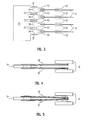
- Fig. 3 shows a side view of the ramp member 80.
- the suspensions 32 are shown in cross section.
- Member 80 has a plurality of ramp surfaces 82 and ledge surfaces 84.
- the suspensions 32 shown by a solid line are in the unloaded position on ledges 84.
- the suspensions shown by a dashed line are in the loaded position, with each one located over one of the surfaces of the disks 12.
- Fig. 4 shows a side view of suspensions 32 in a loaded position over disks 12.
- Fig. 5 shows a side view of suspensions 32 in an unloaded position away from disks 12.
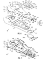
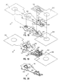
- Fig. 6 shows an exploded view of head 30 and suspension 32. This combination is known as the head/suspension assembly and is referred to by the general reference number 98.
- Fig. 7 shows a perspective view of the completed assembly 98.
- Suspension 32 comprises an arm mounting block 100, a load beam 102, a flexure member 104, a stiffener member 106, a spacer member 108, and a slider plate member 110.
- Head 30 comprises an air bearing slider 120 having a magnetic read/write transducer element 122.
- a plurality of electrical pads 124 are electrically connected to the element 122.
- the slider 120 has an air bearing surface 126.
- a plurality of axes 127, 128, and 129 represent longitudinal, latitudinal, and vertical directions, respectively.
- Mounting block 100 is made of a rigid material, such as stainless steel, which is able to resist deflection.
- Mounting block 100 may be of a thickness in range of 0.1 to 0.3 mm and is 0.2 mm thick in a preferred embodiment.
- Mounting block 100 has a swage aperture 130 which is surrounded by swage flange 132.
- Flange 132 has a swage lip 134. After the manufacture of the assemblies 98, they are attached to the actuator arms 34 by swaging.
- the mount block 100 may be omitted and the load beam 102 attached directly to the arm 34 by welding or other appropriate connection.
- Load beam 102 is made of a thin rigid material, such as stainless steel, and is of a thickness in the range of 0.025 to 0.075 mm, and preferably 0.05 mm.
- the beam 102 is substantially triangular in shape.
- Beam 102 has a mounting section 140 having a swage aperture 142 which is sized to receive the swage flange 132 of mounting block 100.
- the bottom surface of beam 102 is attached to mounting block 100 by suitable means such as spot welding. Spot welding locations for the suspension 32 are designated by the reference member 143.
- Beam 102 has a pair of wing tabs 144 which extend over the edge of the underlying mounting block 100. Tabs 144 each have an aperture 146. Aperture 146 may be used in wire mounting process as described in US Patent 5,074,029.
- Beam 102 has a spring section 150 located forward of the mounting section 140.
- Spring section 150 has a rectangular spring aperture 152 which is flanked by two spring legs 154.
- Beam 102 has a rigid section 160 located forward of the spring section 150.
- the spring legs 154 allow the rigid section 160 to bend about an axis 156 such that the head 30 moves up or down.
- the spring coefficient may be varied as desired by increasing or decreasing the size of the aperture 152 or eliminating aperture 152 entirely.
- the spring legs 154 are each 1.4 mm wide with an aperture width of 2.6 mm and which gives a vertical stiffness of 2.1 grams/mm.
- Rigid section 160 has an aperture 162 and a tooling aperture 164.
- a finger tab 166 and a wiring tab 167 extend from the sides of beam 102 near aperture 164.
- the finger tab 166 is used to align the beam 102 during the assembly process.
- the forward end of rigid section 160 narrows to a tip 168.
- Tip 168 has a load dimple 170.
- the dimple 170 faces in a downward direction and is formed by a stamping process.
- the distance from the center of aperture 142 to the dimple 170 may be in the range of 12-20 mm and preferably 14.65 mm.
- a pair of capture tabs 172 extend from the side of section 160 proximate the tip 168.
- the captured tabs are bent to a lower elevation than the rest of the beam 102 and are stamped or etched thinner than the rest of the load beam material to a preferred thickness of 0.03 mm.
- the load beam 160 is flat and not deformed.
- the stiffener member 106 is made of a thin rigid material, such as stainless steel, and is of a thickness in the range of 0.025 mm to 0.05 mm, and preferably 0.033 mm.
- the stiffener member 106 is substantially triangular in shape and corresponds generally to the rigid section 160 of beam 102.
- the member 106 has a top ledge section 180, a bottom section 182, a pair of side walls 184, and a front wall 186.
- Side walls 184 are substantially perpendicular to bottom section 182.
- Front wall 186 preferably slopes at a gradual angle upward from bottom section 182 to top ledge 180. Alternatively, front wall 186 may also be substantially perpendicular to bottom section 182 or may be deleted altogether.
- the stiffener member 106 has an aperture 188 and a tooling aperture 190 which correspond to apertures 162 and 164, respectively, of beam 102.
- the stiffener member features 182, 184 and 186 are formed by a stamping process.
- the stiffener member 106 is attached to the bottom surface of beam 102 by spot welding top ledge section 180 to rigid section 160 of beam 102.
- the stiffener member 106 does not cover the spring section 150 nor does it cover the tip 168, including dimple 170 and capture tabs 172. In the preferred embodiment, the stiffener member extends from the end of the spring section 150 to a point proximate the tip 168.
- stiffener member 106 When stiffener member 106 is attached to beam 102 an interior chamber 192 is formed there between.
- the interior chamber is completely enclosed along a cross sectional plane along the latitudinal 128 and vertical 129 directions.
- the combination of the load beam 102 and stiffener member 106 creates a light weight but very rigid section. This is accomplished without adding significantly to the overall profile height of the assembly 98.
- the side walls 184 need only be of a very small height to achieve the desired rigid structure. In a preferred embodiment, the side walls are of a height in the range of 0.1 mm to 0.3 mm and preferably 0.2 mm.
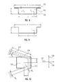
- Fig. 8 shows a cross-sectional view of the load beam 102 and member 106 (box structure).
- K B 1 12 Eat 3 [2 + 6 ⁇ 2 ⁇ (2 - ⁇ ) + 2 ( ⁇ ) ⁇ 3 (1 - 3(1 + 2 ⁇ ) 2 )]
- K T Gat 3 3 [ 3(1 + ⁇ (1 + 2 ⁇ ) 2 ) 1 + ⁇ + 2 (1 + ⁇ ) ⁇ + 1 - ⁇ ]
- Fig. 9 shows an open suspension structure for sake of comparison with the box structure of the present invention.
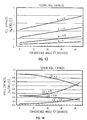
- K B bending stiffness
- K T torsional stiffness
- the units of stiffness have been normalized. It can be seen that the box structure has from 1.5 to 10 times better stiffness than an open structure of similar size.
- Fig. 11 shows a graph of torsional stiffness vs. (h/t) for box and open structures. The units of stiffness have been normalized. It can be seen that the box structure has from five to two hundred times more torsional rigidity than an open structure of similar size.
- Flexure 104 is made of a thin rigid material, such as stainless steel, and is of a thickness in the range of 0.02 mm to 0.03 mm, and preferably 0.025 mm.
- the flexure 104 is flat and unformed and is substantially triangular in shape.
- Flexure 104 has a tooling aperture 200 which corresponds to tooling apertures 164 and 190.
- Flexure 104 has a tongue section 202 which is substantially similar in size and shape to the forward portion of the rigid section 160 of load beam 102. Tongue 202 is surrounded by an aperture 204.
- Aperture 204 is comprised of a pair of slot sections 206 and one gap section 208. Slot sections 206 separate tongue section 202 from a pair of flexure legs 210.
- a tab section 212 is connected to the ends of legs 210 and is separated from tongue 202 by gap section 208.
- Flexure 104 is spot welded to the top surface of rigid section 160 of beam 102.
- Legs 210 are sized such that they extend freely beyond the sides of load beam 102.
- Legs 210 have a bend or knee 214 about halfway along their length.
- Gap section 208 is sized such that the dimple 170 of beam 102 remains uncovered.
- Capture tabs 172 of beam 102 are sized to extend below legs 210.
- Spacer member 108 is spot welded to the bottom side of tab section 212 of flexure 104.
- Spacer member 108 has a shape substantially similar to tab 212.
- Member 108 has a finger tab 220, a wiring tab 221, and a concave edge 222.
- Concave edge 222 is sized to provide clearance for the tip 168 of beam 102.
- Spacer member 108 is made of a thin rigid material, such as stainless steel, and is preferably substantially the same thickness as the material of load beam 102.
- Slider plate member 110 is shaped substantially similar to spacer 108. Member 110 has finger tabs 230. Member 110 also has a dimple tongue 232 which is shaped to extend below and contact dimple 170 of beam 102. In an alternative embodiment, dimple 170 may be formed in slider plate member 110 and project upward to contact the tip of load beam 102 which no longer has a dimple. Member 110 is spot welded to spacer 108. Slider 120 is cemented to member 110 by an appropriate adhesive such as cyanoacrylate. Slider 120 is connected to plate 110 such that dimple 170 is positioned over the center of gravity of slider 120. Slider 120 is made of a wear resistant material and is preferably made of ceramic.
- the centerline of the flexure legs are spaced further apart at the base, where the flexure is connected to the load beam and closer together where the legs are joined to the tab section 212.
- the width of the legs are wider at the base and narrower at the tab.
- the centerlines of the legs are not straight lines, but have bend 214 where the angle changes such that each centerline forms a convex curve or polygram with respect to the longitudinal centerline of the suspension.
- the flexure 104 the following equations are given:
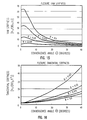
- Figs. 13, 14, 15, and 16 show graphs of roll, pitch, yaw and tangential stiffness versus convergence angle ⁇ for flexure 104. The units of stiffness have been normalized.
- Fig. 17 shows a graph of slider rotation angle versus the slider location (a/L) for three different tapers (B 1 /B 2 ).
- the units of angle have been normalized by g/L, where g is the height of the dimple 170. It can be seen that the taper of legs 210 helps reduce any unwanted rotation.
- the centerlines of the flexure legs are spaced apart 2.9 mm at the base, 2.5 mm at the knee and 0.8 mm at the tab section.
- the flexure leg widths are 0.55 mm at the base, 0.4 mm at the knee and 0.3 mm at the tab section.
- the angle of the flexure legs and the tapered width and length were optimized to increase the lateral stiffness to 35 N/mm while keeping pitch and roll stiffnesses low.
- Figs. 18, 19 and 20 show the manufacture of the suspension 32 of the present invention.
- Fig. 18 shows an exploded view of mounting block 100, a sheet 300, a sheet 302, and a sheet 304.
- Sheets 300, 302 and 304 are thin sheets of stainless steel which are etched to form the desired parts.
- Sheet 300 contains the flexure 104.
- Sheet 302 contains the load beam 102 and spacer 108.
- Sheet 304 contains the stiffener member 106 and the slider plate member 110. It can be seen, that load beam 102 and spacer 108 are the same thickness, as are stiffener member 106 and slider plate member 110.
- sheet 302 is stamped in order to form the lower elevation portions of wiring tabs 167 and 221, capture tabs 172 and dimple 170.
- Sheet 304 is stamped to form the chamber 192 of the stiffener member 106.
- the parts are then stacked and positioned as shown in Fig. 19.
- the parts are spot welded together at welds 143.
- the excess material of the sheets 300, 302 and 304 is cut away as shown in Fig. 20.
- the spring portion 150 is then bent slightly downward to the desired angle needed to position the slider 120 over the disk.
- the slider 120 and the wiring are attached.
- the slider 120 has a thickness of 0.425 mm.
- FIG. 21 shows a perspective view of the assembly 98 when placed in a tooling jig.
- a tooling jig comprises pegs 310, 312, 314 and 316.
- the peg 310 passes through apertures 130 of block 100 and aperture 142 of beam 102.
- Peg 312 passes through apertures 190, 164 and 200 of stiffener 106, beam 102 and flexure 104, respectively.
- the pegs 310 and 312 are used to keep the individual parts in proper alignment during manufacture of assembly 98.
- a final step in the manufacture of assembly 98 is the addition of wiring leads 318.
- Wiring leads 318 connect the electrical pads 124 of head 30 to the read/write channel 58.
- the leads 318 are ultrasonically bonded to the pads 124 of head 30.
- Leads 318 are then attached to assembly 98 by adhesive drops 320 as described in US Patent 5,074,029. Suitable adhesives include ultraviolet curing adhesives.
- the leads 318 are attached to wiring tabs 221 and 167.
- the pegs 314 and 316 are used to properly position the leads 318 during attachment.
- the leads 318 are then passed on to the read/write channel 58.
- the side to which the leads 318 are routed on assembly 98 is determined by the orientation of the assembly 98 in the disk stack.
- the leads 318 are preferably routed to the side of assembly 98 furthest away from the spindle 14.
- Fig. 22 shows a perspective view of the assembly 98 using an alternative wiring scheme.
- the leads 318 are routed over the top of the suspension.
- Peg 312 has a slot 322 for aligning the leads 318 during attachment.
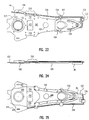
- Figs. 23, 24, and 25 show a top, side, and bottom view, respectively, of the completed assembly 98 including leads 318.
- Fig 26 shows a perspective view of the head portion of assembly 98.
- Figs. 27 and 28 show two different cross sectional views of the portion of Fig. 26.
- the dimple 170 makes a point contact with the tongue 232 of plate 110. This allows slider 120 to pitch (rotate about the latitudinal axis 128) and roll (rotate about the longitudinal axis 127). To achieve this movement, legs 210 bend in the vertical direction 129. It can be seen that capture tabs 172 limit the bending of legs 210 in a downward direction. This limitation protects the assembly 98 and especially the wiring leads 318 from shock damage during assembly and whenever the head 30 is unloaded from the disk surface. This limitation is essential in the alternate wiring scheme shown in Fig. 22.
- the height of dimple 170 must be selected carefully to position capture tabs 172 in the center of the vertical clearance between the slider 120 and flexure legs 210.
- the dimple height is selected large enough to create clearance between the slider 120 and the tip of stiffener ledge 180 which is proximate load beam tip 168.
- the tip of the load beam, stiffener and flexure directly over the slider deflects due to the load transmitted to the air bearing through dimple 170.
- the clearance must be large enough to allow for this bending deflection and allow for pitch (rotation about latitudinal axis 128) and roll (rotation about longitudinal axis 127) excursions of the slider.
- the dimple height cannot be selected too large, however, since the dimple height directly adds to the profile height of the suspension assembly through the slider and limits how close the disks can be spaced. In the preferred embodiment an optimal dimple height has been found to be 0.05 mm.
- the solid height of the slider 120, slider mounting plate 110, dimple 170, load beam tip 168 and flexure 104 in the preferred embodiment is 0.583 mm.
- the preferred side routing of the wires is contained within this height, such that the wires do not reduce the ability to merge the suspension systems in the smallest possible disk to disk spacing of about 1.5 mm as shown in Figure 5 allowing 0.17 mm per suspension unload clearance. If the smallest disk to disk spacing is not required, the alternate wiring shown in Fig. 22 may be used with a disk to disk spacing of 1.8 mm or greater.
- the head/suspension assembly 98 is parked off of disks 12 on ledge 84 of ramp member 80. This is the unloaded condition.
- Spindle motor 16 rotates the disks 12.
- controller unit 50 causes actuator motor 36 to move assembly 98 inward towards the disks 12.
- the assemblies 98 slide down the ramps 82 until they are positioned proximate a surface of one of the disks 12. The data is then recorded or read from a data track of one of the disks 12.
- the rotation of disks 12 causes an air bearing to be formed at air bearing surface 126 of slider 120. This causes the slider 120 to float above the surface of the disks 12.
- Spring section 150 of load beam 102 exerts a force to bring the slider 120 towards the surface of the disks 12 such that the proper fly height is maintained.
- the assembly 98 maintains a rigid structure between the spring section 150 and the head 30. This is achieved in a very low profile by the use of the stiffener member 106 and beam 102.
- the assembly 98 also provides a low profile pivoting assembly for the slider 120. This is accomplished by a series of thin stacked members. This allows precise manufacture of the pivoting assembly even at very small dimensions.
- An additional feature of the pivoting assembly is the use of the capture tabs 172. These tabs 172 prevent the legs 210 from bending too far in the vertical direction. This limits the movement of the head 30 away from the tip 168 of beam 102 when the head is unloaded from the disk 12 and during manufacture of the suspension. This helps prevent the wire leads 318 from becoming bent or damaged.
- the present invention gives several manufacturing advantages compared with prior art suspensions.
- the flexure is not formed to create a clearance between the flexure legs and the slider as is the case in prior art. Instead, the clearance is created by a stack of thin members as already described so arranged as to allow the flexure to be attached to the load beam from the side opposite the slider.
- the flexure is attached between the load beam and the slider.
- the arrangement of the present invention allows a "tops down" assembly method where the parts are handled in strips of multiple components. The capture tab feature is thus created without any interleaving of components prior to welding. Since the flexure goes onto the stack last and is unformed, there is no manufacturing variations of the clearance dimension or static pitch and roll angles.
- flexure thickness can be varied by design to allow multiple products to be manufactured without affecting any forming dies and without the normal variation of dimensions usually experienced in forming flexures.
- Different thickness flexures can be used for different size sliders or different size air bearings with their unique stiffness requirements.
- Resonance modes which produce lateral motion of the slider along axis 128 are undesirable because they limit the performance of the actuator.
- Such modes include torsion and lateral sway modes.
- Prior art flanged open structure suspensions tend to have some of these modes below 3000 Hz.
- the boxed structure of the present invention will have higher resonance frequencies.
- Fig. 29 shows a graph of gain versus frequency at the spring legs 154 and slider 120 of the suspension.
- the suspension of the present invention has high frequency radial resonances with controllable gain.
- the first torsion mode is about 2000 - 3000 Hz and it has a relatively higher gain. This compares with a first torsional mode of about 5000 Hz with about zero gain for the present invention.
- prior art suspensions commonly require the addition of dampers at considerable additional cost, whereas the present invention suspension does not require dampers.
- the measurement in Fig. 29 was performed on a shaker where the shaker mass is very high when compared to an actual disk drive actuator, the gain when mounted on the actuator would be much lower.
- the box section also results in a very low and smooth side profile, compared to conventional side flanged suspension of prior art. This small side area and smoother surfaces result in smaller excitations of the suspension due to air flow turbulence and results in smaller off-track errors due to the air flow in the disk drive system.
- the overall result of the present invention is a low profile suspension which is ideally suited for use with smaller sized heads.
- the low profile enables the disks to be spaced closer together thereby allowing a disk drive system to have more disks in order to increase the data storage capacity or to have the same capacity in a smaller package height.
- flexure 104 is not a separate piece, but is integral with load beam 102 and spacer member 108. Flexure legs 210 are connected to load beam 102 at finger tabs 166 and to spacer member 108.
Landscapes
- Supporting Of Heads In Record-Carrier Devices (AREA)
- Adjustment Of The Magnetic Head Position Track Following On Tapes (AREA)
- Vehicle Body Suspensions (AREA)
Claims (16)
- Ein Trägersystem für einen Lese-/Schreibkopf eines Plattenlaufwerks mit:einem Träger (102), der ein erstes Ende (140) zum Anschluß eines Stützglieds (100), einem zweiten Ende (160) mit einem vorstehenden Kontaktpunkt (170;einem Aussteifungsglied (106), das zwischen dem ersten Ende (140) und dem zweiten Ende (160) mit dem Träger (102)verbunden ist, wobei entlang einer Querschnittsebene eine abgeschlossene Innenkammer (192) gebildet wird;einem flexiblen Glied (104), das mit dem zweiten Ende (160) des Trägers (102) verbunden ist, wobei das flexible Glied (104) eine Vielzahl von flexiblen Schenkelgliedern (210, 212) hat, die sich über den Träger (102) hinaus erstrecken; undeinem Wandlermontageglied (120, 108, 110) zur Montage eines Wandlerelements (122), das mit den flexiblen Schenkelgliedern (210, 212)verbunden ist, wobei das Wandlermontageglied (120) den Kontaktpunkt (170) des Trägers (102) berührt.
- Das System nach Anspruch 1, wobei der Träger (102) einen Federbereich (150) hat, der zwischen dem Aussteifungsglied (106) und dem Trägerglied liegt.
- Das System nach Anspruch 1 oder 2, wobei der Träger (102) ein Paar Federbeine (154) hat, die eine Öffnung (152) umgeben, die zwischen dem Aussteifungsglied und dem Trägerglied liegt.
- Ein System nach einem der Ansprüche 1 bis 3, wobei das Aussteifungsglied (106) wenigstens drei Seiten (182, 184, 186) von der eingeschlossenen Innenkammer (192) bildet.
- Ein System nach einem der Ansprüche 1 bis 4, wobei das Aussteifungsglied (106) einen unteren Bereich (182) enthält, einen Seitenwandbereich (184, 186), der mit dem unteren Bereich verbunden ist, und einen vorspringenden Bereich (180), der mit dem Seitenwandbereich verbunden ist.
- Ein System nach einem der Ansprüche 1 bis 5, wobei das Wandlermontageglied (120, 108, 110) einen auf einem flüssigen Polster gelagerten Schieber (120) enthält, ein erstes Plattenglied (110), das mit dem Schieber verbunden ist, wobei das erste Plattenglied einen Bereich (232) hat, der das vorspringende Kontaktglied berührt, und ein zweites Plattenglied (108), das zwischen dem ersten Plattenglied (110) und den flexiblen Schenkelgliedern (210, 212) angeschlossen ist.
- Ein System nach einem der Ansprüche 1 bis 6, wobei sich der Schieber und das Aussteifungsglied auf der gleichen Seite des Trägers (102) befinden.
- Ein System nach einem der Ansprüche 1 bis 7, wobei die Dicke des ersten Plattenglieds im wesentlichen gleich der Dicke des Materials von dem Aussteifungsglied (106) ist.
- Ein System nach einem der Ansprüche 1 bis 8, wobei die Dicke des zweiten Plattenglieds im wesentlichen gleich der Dicke des Materials von dem Träger (102) ist.
- Ein System nach einem der Ansprüche 1 bis 9, wobei der Träger (102) außerdem wenigstens einen erweiterten Bereich (172) enthält, der sich zwischen einem der flexiblen Schenkelglieder und dem Wandlermontageglied erstreckt.
- Ein System nach einem der Ansprüche 1 bis 10, wobei die flexiblen Schenkelglieder (210, 212) jeweils eine Mittellinie haben, die in einem ersten Winkel mit Bezug auf einen anderen konvergiert.
- Ein System nach einem der Ansprüche 1 bis 11, wobei jedes der flexiblen Schenkelglieder (210, 212) eine Krümmung (214) in seinen Mittellinien hat, die jedes flexible Schenkelglied (210 oder 212) in einen ersten und zweiten Teil dividiert, so daß die Mittellinien der ersten Teile in einem ersten Winkel konvergieren, und die Mittellinien der zweiten Teile in einem zweiten Winkel konvergieren.
- Ein System nach einem der Ansprüche 1 bis 12, wobei die flexiblen Schenkelglieder (210, 212) sich in der Breite verjüngen.
- Ein System nach einem der vorhergehenden Ansprüche, das außerdem enthält:eine Datenspeicherungsplatte (12), die sich in der Nähe des Wandlermontageglieds befindet;ein Rotationsmittel (14, 16), das mit der Platte verbunden ist, welche die Platte dreht; undein Bewegungsmittel (36), das mit dem Stützglied verbunden ist, um das Wandlermontageglied in bezug auf die Platte zu verfahren.
- Ein System nach einem der vorhergehenden Ansprüche, das außerdem ein Wandlerelement (122) enthält, das mit dem Wandlermontageglied verbunden ist.
- Ein Plattenlaufwerksystem, das ein Trägersystem enthält, wie dieses in einem der vorhergehenden Ansprüche angemeldet wurde.
Applications Claiming Priority (2)
| Application Number | Priority Date | Filing Date | Title |
|---|---|---|---|
| US12287993A | 1993-09-16 | 1993-09-16 | |
| US122879 | 1993-09-16 |
Publications (2)
| Publication Number | Publication Date |
|---|---|
| EP0644530A1 EP0644530A1 (de) | 1995-03-22 |
| EP0644530B1 true EP0644530B1 (de) | 1999-06-30 |
Family
ID=22405377
Family Applications (1)
| Application Number | Title | Priority Date | Filing Date |
|---|---|---|---|
| EP94306673A Expired - Lifetime EP0644530B1 (de) | 1993-09-16 | 1994-09-12 | Trägersystem für Wandler |
Country Status (9)
| Country | Link |
|---|---|
| US (1) | US5570261A (de) |
| EP (1) | EP0644530B1 (de) |
| JP (1) | JPH0798949A (de) |
| KR (1) | KR950008175A (de) |
| CN (1) | CN1108418A (de) |
| DE (1) | DE69419294T2 (de) |
| MY (1) | MY111296A (de) |
| SG (1) | SG44365A1 (de) |
| TW (1) | TW296837U (de) |
Families Citing this family (30)
| Publication number | Priority date | Publication date | Assignee | Title |
|---|---|---|---|---|
| JP2814450B2 (ja) * | 1994-03-31 | 1998-10-22 | インターナショナル・ビジネス・マシーンズ・コーポレイション | ヘッド・サスペンション・アセンブリおよびその製造方法 |
| JP2955829B2 (ja) | 1994-04-15 | 1999-10-04 | ハッチンソン テクノロジー インコーポレイテッド | ヘッドサスペンション |
| JP3173714B2 (ja) * | 1994-12-08 | 2001-06-04 | インターナショナル・ビジネス・マシーンズ・コーポレ−ション | サスペンション・システム |
| JP3400248B2 (ja) * | 1995-08-30 | 2003-04-28 | インターナショナル・ビジネス・マシーンズ・コーポレーション | ディスク・ドライブ装置用のヘッド・サスペンションのロード・ビーム |
| US5742996A (en) * | 1996-01-03 | 1998-04-28 | International Business Machines Corporation | Method of manufacturing a transducer suspension system |
| US5793569A (en) * | 1996-04-10 | 1998-08-11 | Hutchinson Technology, Inc. | Three piece suspension |
| US5892637A (en) * | 1996-05-10 | 1999-04-06 | International Business Machines Corporation | Multi-piece integrated suspension assembly for a magnetic storage system |
| US5818662A (en) * | 1996-07-15 | 1998-10-06 | International Business Machines Corporation | Static attitude and stiffness control for an integrated suspension |
| US5734526A (en) * | 1996-12-31 | 1998-03-31 | Hutchinson Technology Incorporated | Monocoque head suspension and its method of construction |
| US5812343A (en) * | 1997-01-15 | 1998-09-22 | Seagate Technology, Inc. | Base plate with improved swage performance and reduced mass |
| WO1998044488A1 (en) * | 1997-03-31 | 1998-10-08 | Seagate Technology, Inc. | Flexure microactuator |
| JP3909934B2 (ja) * | 1997-11-06 | 2007-04-25 | 日本発条株式会社 | ディスク装置用サスペンション |
| EP0942412A1 (de) * | 1998-03-13 | 1999-09-15 | STMicroelectronics S.r.l. | Aufhängungsarm mit hohler Struktur für Kopf einer Plattenspeichervorrichtung |
| US7085104B1 (en) | 1999-10-06 | 2006-08-01 | Western Digital (Fremont), Inc. | Low profile head gimbal assembly with shock limiting and load/unload capability |
| US6538850B1 (en) | 1999-10-06 | 2003-03-25 | Read-Rite Corporation | Low profile head gimbal assembly with shock limiting and load/unload capability and method of manufacture thereof |
| US6738226B1 (en) | 2000-01-13 | 2004-05-18 | Jpmorgan Chase Bank | Adhesive control features for disc drive head suspension and flex circuit interconnect |
| AU2002231321A1 (en) | 2000-10-25 | 2002-05-06 | Seagate Technology Llc | Monocoque head suspension |
| SG117391A1 (en) | 2000-11-27 | 2005-12-29 | Seagate Technology Llc | Head actuator for a data storage head having a loss mass with lateral stiffness |
| AU2002228802A1 (en) * | 2000-12-08 | 2002-06-18 | Seagate Technology Llc | Boxy suspension and arm design with high stiffness |
| JP2002269713A (ja) | 2001-03-12 | 2002-09-20 | Tdk Corp | ヘッド支持体の加工方法 |
| US6947257B2 (en) * | 2001-07-11 | 2005-09-20 | Iomega Corporation | System and method of introducing a preferential curvature to a flexible medium for reduced medium vibration and sensor to medium spacing with a disk drive head stack assembly having a non-zero static roll attitude |
| US6741424B1 (en) | 2001-08-31 | 2004-05-25 | Hutchinson Technology, Inc. | Head suspension with rail and stiffener combination |
| US7352533B1 (en) * | 2004-06-18 | 2008-04-01 | Hutchinson Technology Incorporated | Head suspension with polymer stiffener |
| US7660073B2 (en) * | 2006-07-14 | 2010-02-09 | Seagate Technology Llc | Braced suspension for supporting a head slider |
| US7969689B2 (en) | 2007-08-14 | 2011-06-28 | Seagate Technology Llc | Spacer keys with pivoting supports |
| SG165198A1 (en) * | 2009-03-20 | 2010-10-28 | Agency Science Tech & Res | Apparatus for vibration reduction in a hard disk drive |
| JP5634432B2 (ja) * | 2012-04-20 | 2014-12-03 | サンコール株式会社 | 磁気ヘッドサスペンション |
| US9805750B1 (en) | 2016-06-24 | 2017-10-31 | Seagate Technology Llc | Data storage loadbeam stiffening feature |
| JP7077248B2 (ja) * | 2019-02-07 | 2022-05-30 | 株式会社東芝 | ディスク装置 |
| CN112304638A (zh) * | 2020-10-30 | 2021-02-02 | 广州汽车集团股份有限公司 | 一种行人保护aPLI腿动态标定装置、方法 |
Family Cites Families (47)
| Publication number | Priority date | Publication date | Assignee | Title |
|---|---|---|---|---|
| US3931641A (en) * | 1974-08-22 | 1976-01-06 | International Business Machines Corporation | Transducer suspension mount apparatus |
| US4167765A (en) * | 1978-07-27 | 1979-09-11 | International Business Machines Corporation | Transducer suspension mount apparatus |
| US4449155A (en) * | 1981-11-16 | 1984-05-15 | Dma Systems Corporation | Gimbal assembly for flying magnetic transducer heads |
| JPH0823976B2 (ja) * | 1983-04-18 | 1996-03-06 | 株式会社東芝 | 磁気記録再生装置 |
| JPS59207065A (ja) * | 1983-05-09 | 1984-11-24 | Nec Corp | 浮動ヘツド支持装置 |
| JPS6035384A (ja) * | 1983-08-08 | 1985-02-23 | Nec Corp | 浮動ヘッド支持装置 |
| EP0155746B1 (de) * | 1984-01-26 | 1988-03-30 | Memorex Corporation | Federelement zur Halterung von Winchester-Gleitmagnetköpfen |
| JPS6163974A (ja) * | 1984-09-05 | 1986-04-02 | Matsushita Electric Ind Co Ltd | ピツクアツプ装置 |
| JPS61192081A (ja) * | 1985-02-20 | 1986-08-26 | Mitsubishi Electric Corp | ヘツド支持装置 |
| JPS61222020A (ja) * | 1985-03-27 | 1986-10-02 | Tdk Corp | 磁気ヘツドの支持機構 |
| US4807054A (en) * | 1985-08-14 | 1989-02-21 | Miniscribe Corporation | Transducer support assembly having laterally offset flexures |
| GB2193833B (en) * | 1986-08-12 | 1990-09-19 | Hutchinson Technology | Magnetic head arm assembly |
| US4797763A (en) * | 1986-08-13 | 1989-01-10 | Micropolis Corporation | Compact magnetic head flexible suspension |
| US4724500A (en) * | 1986-08-14 | 1988-02-09 | Tandon Corporation | Mechanism for preventing shock damage to head slider assemblies and disks in rigid disk drive |
| KR910001150B1 (ko) * | 1986-09-19 | 1991-02-25 | 가부시끼가이샤 히다찌세이사꾸쇼 | 헤드 슬라이더 지지장치 |
| JPS63261584A (ja) * | 1987-04-20 | 1988-10-28 | Hitachi Ltd | ヘツドスライダ支持装置 |
| JPS63281282A (ja) * | 1987-05-13 | 1988-11-17 | Hitachi Ltd | スライダ−支持装置 |
| US4853811A (en) * | 1987-08-03 | 1989-08-01 | International Business Machines Corporation | Magnetic disk drive with low profile head-suspension system |
| US4868694A (en) * | 1987-12-11 | 1989-09-19 | Magnetic Peripherals Inc. | Flexure for rotary actuated arm |
| US4991045A (en) * | 1987-12-21 | 1991-02-05 | Hutchinson Technology, Inc. | Suspension assembly |
| JPH01213821A (ja) * | 1988-02-23 | 1989-08-28 | Toshiba Corp | 磁気記録媒体駆動装置の磁気ヘッド構造 |
| US5003420A (en) * | 1988-03-23 | 1991-03-26 | Digital Equipment Corporation | Low profile head-load beam slider arm for disk drive |
| US4992898A (en) * | 1988-03-31 | 1991-02-12 | Applied Magnetic Corporation | Magnetic head slider suspension assembly having inverted load rails |
| JPH01277380A (ja) * | 1988-04-22 | 1989-11-07 | Internatl Business Mach Corp <Ibm> | ヘツド・サスペンシヨン・ロードビーム |
| DE3870230D1 (de) * | 1988-04-29 | 1992-05-21 | Ibm | Magnetkopftraegeraufbau und zugriffseinrichtung fuer eine platteneinheit. |
| US5079660A (en) * | 1988-07-05 | 1992-01-07 | Mitsubishi Denki Kabushiki Kaisha | Magnetic head suspension assembly for reducing vibration effects |
| US4937693A (en) * | 1988-10-20 | 1990-06-26 | Hewlett-Packard Company | Staggered heads for minimizing disk spacing in a disk drive |
| US5138507A (en) * | 1989-03-27 | 1992-08-11 | Computer & Communications Technology Corp. | Disk head assembly flexure with improved motion stability |
| US5001583A (en) * | 1989-04-19 | 1991-03-19 | Tdk Corporation | Flexible polymeric resinous magnetic head supporting device |
| DE68919683T2 (de) * | 1989-05-13 | 1995-05-24 | Ibm Deutschland | Kleinprofil-Magnetkopfaufhängung. |
| US5208712A (en) * | 1989-06-01 | 1993-05-04 | Quantum Corporation | Data head load beam for height compacted, low power fixed head and disk assembly |
| JPH0733668Y2 (ja) * | 1989-06-09 | 1995-08-02 | 株式会社国盛化学 | 冷菓製造装置 |
| JP2585431B2 (ja) * | 1989-07-10 | 1997-02-26 | 株式会社日立製作所 | 磁気ヘッドスライダ支持機構 |
| US4996623A (en) * | 1989-08-07 | 1991-02-26 | International Business Machines Corporation | Laminated suspension for a negative pressure slider in a data recording disk file |
| CA2021359C (en) * | 1989-11-13 | 1994-04-12 | Wayne E. Foote | Magnetic head suspension assembly in a disk drive |
| US5172286A (en) * | 1990-01-03 | 1992-12-15 | Hutchinson Technology, Inc. | Load beam interlocking boss |
| JPH03219473A (ja) * | 1990-01-24 | 1991-09-26 | Matsushita Electric Ind Co Ltd | トランスデューサ支持装置 |
| JPH03238616A (ja) * | 1990-02-16 | 1991-10-24 | Mitsubishi Electric Corp | 磁気ヘッド支持機構 |
| US5115363A (en) * | 1990-02-16 | 1992-05-19 | Digital Equipment Corporation | Head/gimbal assembly having low stiffness cross band flexure |
| JPH06501333A (ja) * | 1990-09-14 | 1994-02-10 | ハッチンソン テクノロジー インコーポレイテッド | 改良形反転レールヘッドサスペンション |
| US5074029A (en) * | 1990-10-02 | 1991-12-24 | International Business Machines Corporation | Method for stringing wire on an actuator arm |
| EP0484906A3 (en) * | 1990-11-09 | 1993-04-28 | Brier Technology | Head mounting device |
| US5198945A (en) * | 1990-11-09 | 1993-03-30 | Hutchinson Technology Incorporated | Magnetic head suspension |
| US5237472A (en) * | 1990-12-19 | 1993-08-17 | Integral Peripherals, Inc. | Rigid disk drive with dynamic head loading apparatus |
| JPH04313870A (ja) * | 1991-04-12 | 1992-11-05 | Hitachi Ltd | ヘッド支持装置及びディスク記憶装置 |
| US5291359A (en) * | 1991-04-29 | 1994-03-01 | Hutchinson Technology Incorporated | Head suspension assembly including a flexure having rails arranged for interfacing with a head ramp |
| JP2870264B2 (ja) * | 1991-11-14 | 1999-03-17 | 松下電器産業株式会社 | 磁気ヘッドスライダ支持装置 |
-
1994
- 1994-07-19 JP JP6166799A patent/JPH0798949A/ja active Pending
- 1994-08-12 TW TW085212155U patent/TW296837U/zh unknown
- 1994-08-16 MY MYPI94002142A patent/MY111296A/en unknown
- 1994-08-16 KR KR1019940020098A patent/KR950008175A/ko not_active Ceased
- 1994-08-16 CN CN94115052A patent/CN1108418A/zh active Pending
- 1994-09-12 EP EP94306673A patent/EP0644530B1/de not_active Expired - Lifetime
- 1994-09-12 DE DE69419294T patent/DE69419294T2/de not_active Expired - Fee Related
- 1994-09-12 SG SG1995002338A patent/SG44365A1/en unknown
-
1995
- 1995-10-20 US US08/546,518 patent/US5570261A/en not_active Expired - Fee Related
Also Published As
| Publication number | Publication date |
|---|---|
| SG44365A1 (en) | 1997-12-19 |
| US5570261A (en) | 1996-10-29 |
| JPH0798949A (ja) | 1995-04-11 |
| DE69419294D1 (de) | 1999-08-05 |
| MY111296A (en) | 1999-10-30 |
| EP0644530A1 (de) | 1995-03-22 |
| TW296837U (en) | 1997-01-21 |
| KR950008175A (ko) | 1995-04-17 |
| CN1108418A (zh) | 1995-09-13 |
| DE69419294T2 (de) | 2000-01-27 |
Similar Documents
| Publication | Publication Date | Title |
|---|---|---|
| EP0644530B1 (de) | Trägersystem für Wandler | |
| CA2154510C (en) | Transducer suspension system | |
| USRE40203E1 (en) | Magnetic head suspension assembly fabricated with integral load beam and flexure | |
| US5115363A (en) | Head/gimbal assembly having low stiffness cross band flexure | |
| US8027128B2 (en) | Suspension and disk drive | |
| US7137187B2 (en) | Integrated lead suspension for high density drive | |
| US4853811A (en) | Magnetic disk drive with low profile head-suspension system | |
| US5790347A (en) | Head suspension load beam and flexure construction for reducing structural height | |
| US5299081A (en) | Magnetic head suspension assembly | |
| US6243235B1 (en) | Transducer suspension system with limiter | |
| EP0362072B1 (de) | Aufhängevorrichtung eines Kopf-Gleitkörpers für ein Aufzeichnungsgerät | |
| US5617274A (en) | Low profile integral flexure for closely packed disks in a disk drive assembly | |
| US6741424B1 (en) | Head suspension with rail and stiffener combination | |
| WO1993017416A1 (en) | Gimbal for magnetic head suspension systems | |
| US5734525A (en) | Head suspension with torsion spring region | |
| US20030137774A1 (en) | Motion limiter for disk drive integrated gimbal suspension | |
| US5455727A (en) | Transducer suspension assembly with a first pair of flanges for raising the resonant frequency and a second pair of flanges for increasing stiffness | |
| US6477017B2 (en) | Disk drive and head suspension unit | |
| US6304420B1 (en) | Preloaded gimbal in a head suspension for limiting head/disc separation | |
| WO2001073765A1 (en) | Dynamically symmetric actuator | |
| USH1425H (en) | Head suspension assembly having improved frequency response, accurate head positioning and minimized flying variation | |
| US7218479B2 (en) | Head support device with bearing and elastic member | |
| US7245456B2 (en) | Head support device and disk drive using the same | |
| US20250191609A1 (en) | Profile Shape Control For Gimbal Assembly | |
| US7586714B2 (en) | Head suspension with rails and support extensions |
Legal Events
| Date | Code | Title | Description |
|---|---|---|---|
| PUAI | Public reference made under article 153(3) epc to a published international application that has entered the european phase |
Free format text: ORIGINAL CODE: 0009012 |
|
| AK | Designated contracting states |
Kind code of ref document: A1 Designated state(s): DE FR GB |
|
| 17P | Request for examination filed |
Effective date: 19950714 |
|
| 17Q | First examination report despatched |
Effective date: 19980205 |
|
| GRAG | Despatch of communication of intention to grant |
Free format text: ORIGINAL CODE: EPIDOS AGRA |
|
| GRAG | Despatch of communication of intention to grant |
Free format text: ORIGINAL CODE: EPIDOS AGRA |
|
| GRAH | Despatch of communication of intention to grant a patent |
Free format text: ORIGINAL CODE: EPIDOS IGRA |
|
| GRAH | Despatch of communication of intention to grant a patent |
Free format text: ORIGINAL CODE: EPIDOS IGRA |
|
| GRAA | (expected) grant |
Free format text: ORIGINAL CODE: 0009210 |
|
| AK | Designated contracting states |
Kind code of ref document: B1 Designated state(s): DE FR GB |
|
| REF | Corresponds to: |
Ref document number: 69419294 Country of ref document: DE Date of ref document: 19990805 |
|
| PGFP | Annual fee paid to national office [announced via postgrant information from national office to epo] |
Ref country code: FR Payment date: 19990917 Year of fee payment: 6 |
|
| ET | Fr: translation filed | ||
| PLBE | No opposition filed within time limit |
Free format text: ORIGINAL CODE: 0009261 |
|
| STAA | Information on the status of an ep patent application or granted ep patent |
Free format text: STATUS: NO OPPOSITION FILED WITHIN TIME LIMIT |
|
| 26N | No opposition filed | ||
| PGFP | Annual fee paid to national office [announced via postgrant information from national office to epo] |
Ref country code: GB Payment date: 20000904 Year of fee payment: 7 |
|
| PGFP | Annual fee paid to national office [announced via postgrant information from national office to epo] |
Ref country code: DE Payment date: 20000920 Year of fee payment: 7 |
|
| PG25 | Lapsed in a contracting state [announced via postgrant information from national office to epo] |
Ref country code: FR Free format text: LAPSE BECAUSE OF NON-PAYMENT OF DUE FEES Effective date: 20010531 |
|
| REG | Reference to a national code |
Ref country code: FR Ref legal event code: ST |
|
| PG25 | Lapsed in a contracting state [announced via postgrant information from national office to epo] |
Ref country code: GB Free format text: LAPSE BECAUSE OF NON-PAYMENT OF DUE FEES Effective date: 20010912 |
|
| GBPC | Gb: european patent ceased through non-payment of renewal fee |
Effective date: 20010912 |
|
| PG25 | Lapsed in a contracting state [announced via postgrant information from national office to epo] |
Ref country code: DE Free format text: LAPSE BECAUSE OF NON-PAYMENT OF DUE FEES Effective date: 20020501 |