EP0644516B1 - Verfahren und Einrichtung zur bidirektionalen Übertragung von Datensignalen - Google Patents
Verfahren und Einrichtung zur bidirektionalen Übertragung von Datensignalen Download PDFInfo
- Publication number
- EP0644516B1 EP0644516B1 EP94112278A EP94112278A EP0644516B1 EP 0644516 B1 EP0644516 B1 EP 0644516B1 EP 94112278 A EP94112278 A EP 94112278A EP 94112278 A EP94112278 A EP 94112278A EP 0644516 B1 EP0644516 B1 EP 0644516B1
- Authority
- EP
- European Patent Office
- Prior art keywords
- signal
- frequency
- sidebands
- lsb
- vehicle
- Prior art date
- Legal status (The legal status is an assumption and is not a legal conclusion. Google has not performed a legal analysis and makes no representation as to the accuracy of the status listed.)
- Expired - Lifetime
Links
- 238000000034 method Methods 0.000 title claims description 13
- 230000005540 biological transmission Effects 0.000 title claims description 10
- 230000002457 bidirectional effect Effects 0.000 title claims description 3
- 230000002596 correlated effect Effects 0.000 claims description 3
- 230000004044 response Effects 0.000 claims description 2
- 238000004891 communication Methods 0.000 description 12
- 238000001228 spectrum Methods 0.000 description 5
- 238000011156 evaluation Methods 0.000 description 3
- 238000010586 diagram Methods 0.000 description 2
- 238000005259 measurement Methods 0.000 description 2
- 230000008569 process Effects 0.000 description 2
- 229940035637 spectrum-4 Drugs 0.000 description 2
- 230000004888 barrier function Effects 0.000 description 1
- 238000006243 chemical reaction Methods 0.000 description 1
- 238000001514 detection method Methods 0.000 description 1
- 239000012530 fluid Substances 0.000 description 1
- 230000006870 function Effects 0.000 description 1
- 230000006698 induction Effects 0.000 description 1
- 230000010354 integration Effects 0.000 description 1
- 230000007246 mechanism Effects 0.000 description 1
- 238000012544 monitoring process Methods 0.000 description 1
- 230000010363 phase shift Effects 0.000 description 1
- 238000012545 processing Methods 0.000 description 1
- 230000035945 sensitivity Effects 0.000 description 1
- 230000001629 suppression Effects 0.000 description 1
Images


Classifications
-
- G—PHYSICS
- G08—SIGNALLING
- G08G—TRAFFIC CONTROL SYSTEMS
- G08G1/00—Traffic control systems for road vehicles
- G08G1/09—Arrangements for giving variable traffic instructions
- G08G1/0962—Arrangements for giving variable traffic instructions having an indicator mounted inside the vehicle, e.g. giving voice messages
- G08G1/0967—Systems involving transmission of highway information, e.g. weather, speed limits
- G08G1/096708—Systems involving transmission of highway information, e.g. weather, speed limits where the received information might be used to generate an automatic action on the vehicle control
- G08G1/096716—Systems involving transmission of highway information, e.g. weather, speed limits where the received information might be used to generate an automatic action on the vehicle control where the received information does not generate an automatic action on the vehicle control
-
- G—PHYSICS
- G01—MEASURING; TESTING
- G01S—RADIO DIRECTION-FINDING; RADIO NAVIGATION; DETERMINING DISTANCE OR VELOCITY BY USE OF RADIO WAVES; LOCATING OR PRESENCE-DETECTING BY USE OF THE REFLECTION OR RERADIATION OF RADIO WAVES; ANALOGOUS ARRANGEMENTS USING OTHER WAVES
- G01S13/00—Systems using the reflection or reradiation of radio waves, e.g. radar systems; Analogous systems using reflection or reradiation of waves whose nature or wavelength is irrelevant or unspecified
- G01S13/74—Systems using reradiation of radio waves, e.g. secondary radar systems; Analogous systems
- G01S13/76—Systems using reradiation of radio waves, e.g. secondary radar systems; Analogous systems wherein pulse-type signals are transmitted
- G01S13/765—Systems using reradiation of radio waves, e.g. secondary radar systems; Analogous systems wherein pulse-type signals are transmitted with exchange of information between interrogator and responder
-
- G—PHYSICS
- G01—MEASURING; TESTING
- G01S—RADIO DIRECTION-FINDING; RADIO NAVIGATION; DETERMINING DISTANCE OR VELOCITY BY USE OF RADIO WAVES; LOCATING OR PRESENCE-DETECTING BY USE OF THE REFLECTION OR RERADIATION OF RADIO WAVES; ANALOGOUS ARRANGEMENTS USING OTHER WAVES
- G01S13/00—Systems using the reflection or reradiation of radio waves, e.g. radar systems; Analogous systems using reflection or reradiation of waves whose nature or wavelength is irrelevant or unspecified
- G01S13/88—Radar or analogous systems specially adapted for specific applications
- G01S13/91—Radar or analogous systems specially adapted for specific applications for traffic control
-
- G—PHYSICS
- G07—CHECKING-DEVICES
- G07B—TICKET-ISSUING APPARATUS; FARE-REGISTERING APPARATUS; FRANKING APPARATUS
- G07B15/00—Arrangements or apparatus for collecting fares, tolls or entrance fees at one or more control points
- G07B15/06—Arrangements for road pricing or congestion charging of vehicles or vehicle users, e.g. automatic toll systems
- G07B15/063—Arrangements for road pricing or congestion charging of vehicles or vehicle users, e.g. automatic toll systems using wireless information transmission between the vehicle and a fixed station
-
- G—PHYSICS
- G08—SIGNALLING
- G08G—TRAFFIC CONTROL SYSTEMS
- G08G1/00—Traffic control systems for road vehicles
- G08G1/01—Detecting movement of traffic to be counted or controlled
- G08G1/052—Detecting movement of traffic to be counted or controlled with provision for determining speed or overspeed
- G08G1/054—Detecting movement of traffic to be counted or controlled with provision for determining speed or overspeed photographing overspeeding vehicles
-
- G—PHYSICS
- G08—SIGNALLING
- G08G—TRAFFIC CONTROL SYSTEMS
- G08G1/00—Traffic control systems for road vehicles
- G08G1/09—Arrangements for giving variable traffic instructions
- G08G1/0962—Arrangements for giving variable traffic instructions having an indicator mounted inside the vehicle, e.g. giving voice messages
- G08G1/0967—Systems involving transmission of highway information, e.g. weather, speed limits
- G08G1/096733—Systems involving transmission of highway information, e.g. weather, speed limits where a selection of the information might take place
- G08G1/096758—Systems involving transmission of highway information, e.g. weather, speed limits where a selection of the information might take place where no selection takes place on the transmitted or the received information
-
- G—PHYSICS
- G08—SIGNALLING
- G08G—TRAFFIC CONTROL SYSTEMS
- G08G1/00—Traffic control systems for road vehicles
- G08G1/09—Arrangements for giving variable traffic instructions
- G08G1/0962—Arrangements for giving variable traffic instructions having an indicator mounted inside the vehicle, e.g. giving voice messages
- G08G1/0967—Systems involving transmission of highway information, e.g. weather, speed limits
- G08G1/096766—Systems involving transmission of highway information, e.g. weather, speed limits where the system is characterised by the origin of the information transmission
- G08G1/096783—Systems involving transmission of highway information, e.g. weather, speed limits where the system is characterised by the origin of the information transmission where the origin of the information is a roadside individual element
-
- G—PHYSICS
- G01—MEASURING; TESTING
- G01S—RADIO DIRECTION-FINDING; RADIO NAVIGATION; DETERMINING DISTANCE OR VELOCITY BY USE OF RADIO WAVES; LOCATING OR PRESENCE-DETECTING BY USE OF THE REFLECTION OR RERADIATION OF RADIO WAVES; ANALOGOUS ARRANGEMENTS USING OTHER WAVES
- G01S13/00—Systems using the reflection or reradiation of radio waves, e.g. radar systems; Analogous systems using reflection or reradiation of waves whose nature or wavelength is irrelevant or unspecified
- G01S13/74—Systems using reradiation of radio waves, e.g. secondary radar systems; Analogous systems
- G01S13/76—Systems using reradiation of radio waves, e.g. secondary radar systems; Analogous systems wherein pulse-type signals are transmitted
- G01S13/767—Responders; Transponders
Definitions
- the invention relates to a method for bidirectional transmission of data signals between a fixed device and a vehicle device in which the fixed Device sends out a signal of a predetermined frequency, the vehicle device receives the transmitted signal, in particular according to the semi-passive transponder principle, with sends back at least one modulation frequency modulated with data and the fixed facility the returned Receives signal and evaluates to determine the transmitted data.
- the invention further relates to a fixed device to carry out the procedure.
- the procedure mentioned at the beginning is to determine the means characterized in that the received Modulation frequencies in both sidebands in relation to the predetermined frequency of the originally broadcast Signal are brought and from the frequency difference of the associated Modulation frequencies in both sidebands one Speed information derived for the vehicle in question becomes.
- the received modulation frequencies are preferably in the baseband is mixed down and there becomes a frequency difference between the down-mixed modulation frequencies detected.
- the device for determining the difference Counters for pulses from the signals in both Sidebands Preferably, the device for determining the difference Counters for pulses from the signals in both Sidebands.
- the counters are through zero crossing detectors with connected meters educated. It expediently generates a pulse generator a control pulse when a predetermined counter reading is reached through the counter.
- the pulse generator can be a Be a comparator whose one input is the counter reading of the Counter and its other input a reference signal can be supplied is.
- Through the control pulses generated for both sidebands can then turn a time measuring device on or off his. At this time measuring device is expediently one Computing device for converting the measured time into Vehicle speed can be connected.
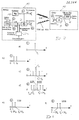
- FIGS 3 and 4 illustrate this communication for the Uplink phase.
- an oscillator 15 generates a constant output signal of a predetermined frequency f T , the frequency spectrum 1 of which is shown in FIG. 4 a.
- This output signal arrives at a transmitting antenna 16, which emits the signal with the predetermined fixed frequency f T as a continuous signal (CW).
- This signal is received by a transmitting / receiving antenna 17 of the vehicle device 13. Due to the movement of the vehicle 14, the signal received by the antenna 17 no longer has the frequency f T , but a frequency f T + f D shifted by the Doppler frequency.
- the vehicle device 13 contains data stored in a memory which are to be transmitted to the beacon 12 during the uplink phase.
- a phase or frequency modulation generator 18, which generates modulation control signals for a modulator 19, is controlled in accordance with this data.
- frequency modulation takes place with two shift frequencies f 1 , f 2 , the frequency spectrum 2 of which is shown in FIG. 4 b.
- the modulated signal which consists of the received carrier frequency f T + f D and the shift frequencies arranged symmetrically thereto in both sidebands, as shown by the frequency spectrum 3 in FIG. 4 c.
- a device 11 is used to obtain the transmitted data Demodulator 22 is provided, at the output of which the transmitted Data are removable.
- the single sideband mixer 21 is - as already illustrated in Figure 3 -
- a gate circuit 25, 25 ' is connected between the zero crossing detector 23, 23' and a counter 24, 24 'counting the zero crossings. This is controlled by a measuring time control 26, 26 '. This receives a start signal which is derived from the communication control as shown in FIG. 2. The measurement time control 26, 26 'can also ensure that only zero crossings are forwarded to the counter 24, 24', each of which lies within a narrow time slot, the intervals of the time slots resulting from the known shift frequencies f 1 , f 2 . This enables interference suppression for interference signals lying outside these time slots.
- the zero crossings of the data signals, which are naturally in the upper Sideband USB and lower sideband LSB are identical counted by the counters 24, 24 '.
- the counter reading of the counter 24, 24 ' reaches a comparator 27, 27', the other Input a reference number from a reference number generator 28 can be fed.
- Vehicle 14 is moving during data communication the beacon 12 too, the frequencies in the upper sideband are USB somewhat higher than in the lower sideband LSB.
- the counter 24 reaches the reference number sooner than the counter 24 ', which counts the zero crossings in the lower sideband LSB.
- the comparator 27, 27 ' generates an output pulse which is transmitted via the measuring time control 26, 26 ' passed on as a control signal for a time measuring device 29 becomes.
- the control pulse of the comparator 27 serves as Start signal for the time measuring device 29, during the control pulse of the comparator 27 'stops the time measuring device.
- the time measured by the time measuring device 29, the Time difference for reaching the specified reference counter reading represents is a measure of speed of the vehicle 14.
- the circuit shown in Figure 5 can be done with simple create digital building blocks and is suitable for integration to an IC.
Landscapes
- Physics & Mathematics (AREA)
- Engineering & Computer Science (AREA)
- General Physics & Mathematics (AREA)
- Radar, Positioning & Navigation (AREA)
- Remote Sensing (AREA)
- Computer Networks & Wireless Communication (AREA)
- Life Sciences & Earth Sciences (AREA)
- Atmospheric Sciences (AREA)
- Electromagnetism (AREA)
- Business, Economics & Management (AREA)
- Finance (AREA)
- Traffic Control Systems (AREA)
- Radar Systems Or Details Thereof (AREA)
- Digital Transmission Methods That Use Modulated Carrier Waves (AREA)
Description
- Figur 1
- - eine schematische Darstellung der Datenkommunikation zwischen einer Bake als feststehende Einrichtung und einem Fahrzeug
- Figur 2
- - eine schematische Darstellung zur Erläuterung der im Zeitmultiplex ablaufenden Kommunikation
- Figur 3
- - Funktionsblockschaltbilder für die Sende-/Empfangseinrichtung der Bake und der Sende-/Empfangseinrichtung des Fahrzeugs
- Figur 4
- - Frequenzspektren zur Erläuterung der an verschiedenen Stellen der Anordnung gemäß Figur 3 auftretenden Signale
- Figur 5
- - ein Blockschaltbild für eine Einrichtung zur Ermittlung der Geschwindigkeit in der Bake
Claims (12)
- Verfahren zur bidirektionalen Übertragung von Datensignalen zwischen einer feststehenden Einrichtung (11) und einer Fahrzeugeinrichtung (13), bei dem die feststehende Einrichtung (11) ein Signal einer vorgegebenen Frequenz (fT) aussendet, die Fahrzeugeinrichtung (13) das ausgesandte Signal, insbesondere nach dem semi-passiven Transponder-Prinzip, mit wenigstens einer Modulationsfrequenz (f1, f2) mit Daten moduliert zurücksendet und die feststehende Einrichtung (11) das zurückgesandte Signal empfängt und zur Ermittlung der übersandten Daten auswertet, dadurch gekennzeichnet, daß die empfangenen Modulationsfrequenzen in beiden Seitenbändern (USB, LSB) in Relation zu der vorgegebenen Frequenz (fT) des ursprünglich ausgesandten Signals gebracht werden und aus Frequenzdifferenzen der zugehörigen Modulationsfrequenzen in beiden Seitenbändern (USB, LSB) eine Geschwindigkeitsinformation für das betreffende Fahrzeug (14) hergeleitet wird.
- Verfahren nach Anspruch 1, dadurch gekennzeichnet, daß die empfangenen Modulationsfrequenzen (f1, f2) in das Basisband heruntergemischt werden und daß eine Frequenzdifferenz zwischen den heruntergemischten Modulationsfrequenzen (f1, f2) festgestellt wird.
- Verfahren nach Anspruch 1 oder 2, dadurch gekennzeichnet, daß zur Auswertung der Frequenzdifferenz Impulse aus Signalen im oberen und unteren Seitenband (USB, LSB) gezählt werden.
- Verfahren nach Anspruch 3, dadurch gekennzeichnet, daß bei Erreichen eines vorgegebenen Zählwerts in einem Seitenband (USB) eine Zeitmeßeinrichtung (29) gestartet und bei Erreichen des vorgegebenen Zählwerts in dem anderen Seitenband (LSB) die Zeitmeßeinrichtung (29) gestoppt wird und daß die gemessene Zeit mit der Geschwindigkeit des Fahrzeugs korreliert wird.
- Feststehende Einrichtung zur Durchführung des Verfahrens nach einem der Ansprüche 1 bis 4 mit einer Sendeeinrichtung (15, 16) für ein Signal mit einer vorgegebenen Frequenz (fT), einer Empfangseinrichtung (20) zum Empfang eines Antwortsignals, das durch Modulation des ausgesandten Signals mit wenigstens einer Frequenz zur Übermittlung von Daten gebildet ist, einer Mischeinrichtung (21) und einer Auswertungseinrichtung (22) zur Ermittlung der übersandten Daten, dadurch gekennzeichnet, daß in der Mischeinrichtung (21) beide Seitenbänder (USB, LSB) des von der Empfangseinrichtung (20) empfangenen Signals unter Verwendung der vorgegebenen Frequenz (fT) des ursprünglich ausgesandten Signals gemischt demoduliert werden und daß die Auswertungseinrichtung eine Einrichtung (22a) zur Feststellung einer Frequenzdifferenz zwischen den Signalen der beiden Seitenbänder aufweist.
- Einrichtung nach Anspruch 5, dadurch gekennzeichnet, daß die Mischeinrichtung ein Einseitenband-Mischer (21) ist, an dessen Ausgängen die in das Basisband heruntergemischten Modulationsfrequenzen (f1, f2) für beide Seitenbänder gesondert anstehen.
- Einrichtung nach Anspruch 5 oder 6, dadurch gekennzeichnet, daß die Einrichtung zur Feststellung des Unterschieds Zähleinrichtungen für Impulse aus den Signalen in beiden Seitenbändern (USB, LSB) aufweist.
- Einrichtung nach Anspruch 7, dadurch gekennzeichnet, daß die Zähleinrichtungen durch Nulldurchgangsdetektoren (23, 23') mit angeschlossenen Zählern (24, 24') gebildet sind.
- Einrichtung nach Anspruch 7 oder 8, gekennzeichnet durch einen Impulserzeuger (27) zur Erzeugung eines Steuerimpulses beim Erreichen eines vorgegebenen Zählerstands durch die Zähleinrichtung.
- Einrichtung nach Anspruch 9, dadurch gekennzeichnet, daß der Impulserzeuger ein Vergleicher (27, 27') ist, dessen einem Eingang der Zählerstand der Zähleinrichtung und dessen anderem Eingang ein Referenzsignal zuführbar ist.
- Einrichtung nach Anspruch 9 oder 10, dadurch gekennzeichnet, daß mit dem für beide Seitenbänder (USB, LSB) erzeugten Steuerimpulsen eine Zeitmeßeinrichtung (29) ein- bzw. ausschaltbar ist.
- Einrichtung nach Anspruch 11, gekennzeichnet durch eine an die Zeitmeßeinrichtung (29) angeschlossene Recheneinrichtung zur Umrechnung der gemessenen Zeit in die Fahrzeuggeschwindigkeit.
Applications Claiming Priority (2)
| Application Number | Priority Date | Filing Date | Title |
|---|---|---|---|
| DE4331286A DE4331286A1 (de) | 1993-09-15 | 1993-09-15 | Verfahren und Einrichtung zur bidirektionalen Übertragung von Datensignalen |
| DE4331286 | 1993-09-15 |
Publications (3)
| Publication Number | Publication Date |
|---|---|
| EP0644516A2 EP0644516A2 (de) | 1995-03-22 |
| EP0644516A3 EP0644516A3 (de) | 1997-06-11 |
| EP0644516B1 true EP0644516B1 (de) | 2000-07-12 |
Family
ID=6497758
Family Applications (1)
| Application Number | Title | Priority Date | Filing Date |
|---|---|---|---|
| EP94112278A Expired - Lifetime EP0644516B1 (de) | 1993-09-15 | 1994-08-05 | Verfahren und Einrichtung zur bidirektionalen Übertragung von Datensignalen |
Country Status (4)
| Country | Link |
|---|---|
| EP (1) | EP0644516B1 (de) |
| CN (1) | CN1050670C (de) |
| DE (2) | DE4331286A1 (de) |
| ES (1) | ES2150458T3 (de) |
Families Citing this family (3)
| Publication number | Priority date | Publication date | Assignee | Title |
|---|---|---|---|---|
| DE4331286A1 (de) * | 1993-09-15 | 1995-03-16 | Bosch Gmbh Robert | Verfahren und Einrichtung zur bidirektionalen Übertragung von Datensignalen |
| BE1011160A3 (nl) * | 1997-05-20 | 1999-05-04 | Smartmove Naamloze Vennootscha | Werkwijze en inrichting voor het tot stand brengen van een draadloze communicatie tussen voertuigen en communicatieapparatuur opgesteld langs de weg. |
| NL1011298C2 (nl) | 1999-02-12 | 2000-08-15 | Amb It Holding | Stelsel voor overdracht tussen voortbewegende objecten en vaste stations. |
Family Cites Families (4)
| Publication number | Priority date | Publication date | Assignee | Title |
|---|---|---|---|---|
| DE3207950A1 (de) * | 1982-03-05 | 1983-09-15 | Bosch Gmbh Robert | Abstandsmessvorrichtung |
| JPS60192282A (ja) * | 1984-03-13 | 1985-09-30 | Nippon Soken Inc | 後続車接近検知装置 |
| IT1183820B (it) * | 1985-05-06 | 1987-10-22 | Fiat Auto Spa | Sistema di comunicazione e segnalazione automatica fra una pluralita di autoveicoli |
| DE4331286A1 (de) * | 1993-09-15 | 1995-03-16 | Bosch Gmbh Robert | Verfahren und Einrichtung zur bidirektionalen Übertragung von Datensignalen |
-
1993
- 1993-09-15 DE DE4331286A patent/DE4331286A1/de not_active Withdrawn
-
1994
- 1994-08-05 ES ES94112278T patent/ES2150458T3/es not_active Expired - Lifetime
- 1994-08-05 EP EP94112278A patent/EP0644516B1/de not_active Expired - Lifetime
- 1994-08-05 DE DE59409432T patent/DE59409432D1/de not_active Expired - Fee Related
- 1994-09-14 CN CN94115883A patent/CN1050670C/zh not_active Expired - Fee Related
Also Published As
| Publication number | Publication date |
|---|---|
| CN1115852A (zh) | 1996-01-31 |
| EP0644516A2 (de) | 1995-03-22 |
| DE4331286A1 (de) | 1995-03-16 |
| DE59409432D1 (de) | 2000-08-17 |
| EP0644516A3 (de) | 1997-06-11 |
| CN1050670C (zh) | 2000-03-22 |
| ES2150458T3 (es) | 2000-12-01 |
Similar Documents
| Publication | Publication Date | Title |
|---|---|---|
| DE4242700C2 (de) | Verfahren zur Messung des Abstandes und der Geschwindigkeit von Objekten | |
| EP0567889B1 (de) | System zur bidirektionalen Datenübertragung zwischen mehreren feststehenden Einrichtungen und einem Fahrzeug | |
| DE69020203T2 (de) | Verfahren und Gerät zur Hilfe des Landfahrzeugverkehrs. | |
| DE2925576A1 (de) | Fm-cw-radargeraet | |
| US4079377A (en) | FM-CW radar for range and relative speed determination | |
| EP1466189B1 (de) | Verfahren zur abstandsbestimmung zwischen einer basisstation und einem mobilen objekt, sowie basisstation und identifikationssystem für ein derartiges verfahren | |
| DE69317186T2 (de) | System zur Bestimmung von zumindest einem Verkehrsregelungsparameter für Fahrzeuge | |
| DE2032211A1 (de) | System zur Überwachung von Fahrzeugen | |
| EP0789898B1 (de) | Verfahren zur positionsbestimmung eines fahrzeuges auf einer strasse | |
| DE2265444C2 (de) | Einrichtung zur Messung des Abstandes eines Gegenstandes von einem Landfahrzeug | |
| DE2158793B2 (de) | Einrichtung zum Messen und Anzeigen des Abstandes und/oder der Abstandsänderung zwischen einem Kraftfahrzeug und einem Hindernis | |
| EP0519361B1 (de) | Dauerstrich-Radargerät, zusätzlich als Sender für die Informationsübertragung verwendbar | |
| DE19946168B4 (de) | FMCW-Verfahren zum Bestimmen des Abstandes zwischen zwei Fahrzeugen | |
| DE19703237C1 (de) | Radar-Abstandsmesser | |
| DE10348216B4 (de) | Objekterfassungssystem für ein Fahrzeug | |
| EP0644516A2 (de) | Verfahren und Einrichtung zur bidirektionalen Übertragung von Datensignalen | |
| DE19503818B4 (de) | Verfahren und Einrichtung zur bidirektionalen Übertragung von Datensignalen | |
| DE3414159C2 (de) | ||
| EP0919000A1 (de) | Verfahren zur identifizierung eines fahrzeugs auf einer strasse | |
| DE2305941B2 (de) | Fahrzeughindernisradar mit abwechselndem FM/CW- und CW-Betrieb zur Entfernungs- bzw. Geschwindigkeitsmessung | |
| DE4313352C2 (de) | Verfahren und Vorrichtung zum automatischen Feststellen von sich bewegenden Personen und/oder Fahrzeugen nach dem Doppler-Prinzip | |
| DE3027981C2 (de) | ||
| DE4035398A1 (de) | Verfahren zur hochfrequenten datenuebertragung von fahrinformationen und vorrichtung dazu | |
| DE3908771C2 (de) | Verfahren zur Messung der Entfernung bewegter Objekte mittels eines Dopplermeßradars sowie Dopplermeßradar zum Ausführen des Verfahrens | |
| DE69131324T2 (de) | Hochleistungsapparat zum messen von betriebsparametern und zeiten von über eine rennstrecke fahrenden fahrzeugen |
Legal Events
| Date | Code | Title | Description |
|---|---|---|---|
| PUAI | Public reference made under article 153(3) epc to a published international application that has entered the european phase |
Free format text: ORIGINAL CODE: 0009012 |
|
| AK | Designated contracting states |
Kind code of ref document: A2 Designated state(s): CH DE ES FR IT LI SE |
|
| PUAL | Search report despatched |
Free format text: ORIGINAL CODE: 0009013 |
|
| AK | Designated contracting states |
Kind code of ref document: A3 Designated state(s): CH DE ES FR IT LI SE |
|
| 17P | Request for examination filed |
Effective date: 19971211 |
|
| GRAG | Despatch of communication of intention to grant |
Free format text: ORIGINAL CODE: EPIDOS AGRA |
|
| 17Q | First examination report despatched |
Effective date: 19990930 |
|
| GRAG | Despatch of communication of intention to grant |
Free format text: ORIGINAL CODE: EPIDOS AGRA |
|
| GRAH | Despatch of communication of intention to grant a patent |
Free format text: ORIGINAL CODE: EPIDOS IGRA |
|
| GRAH | Despatch of communication of intention to grant a patent |
Free format text: ORIGINAL CODE: EPIDOS IGRA |
|
| GRAA | (expected) grant |
Free format text: ORIGINAL CODE: 0009210 |
|
| AK | Designated contracting states |
Kind code of ref document: B1 Designated state(s): CH DE ES FR IT LI SE |
|
| REG | Reference to a national code |
Ref country code: CH Ref legal event code: EP |
|
| REG | Reference to a national code |
Ref country code: CH Ref legal event code: NV Representative=s name: SCINTILLA AG, DIREKTION |
|
| REF | Corresponds to: |
Ref document number: 59409432 Country of ref document: DE Date of ref document: 20000817 |
|
| ITF | It: translation for a ep patent filed | ||
| ET | Fr: translation filed | ||
| REG | Reference to a national code |
Ref country code: ES Ref legal event code: FG2A Ref document number: 2150458 Country of ref document: ES Kind code of ref document: T3 |
|
| PLBE | No opposition filed within time limit |
Free format text: ORIGINAL CODE: 0009261 |
|
| STAA | Information on the status of an ep patent application or granted ep patent |
Free format text: STATUS: NO OPPOSITION FILED WITHIN TIME LIMIT |
|
| 26N | No opposition filed | ||
| PGFP | Annual fee paid to national office [announced via postgrant information from national office to epo] |
Ref country code: FR Payment date: 20010824 Year of fee payment: 8 |
|
| PGFP | Annual fee paid to national office [announced via postgrant information from national office to epo] |
Ref country code: SE Payment date: 20010827 Year of fee payment: 8 Ref country code: CH Payment date: 20010827 Year of fee payment: 8 |
|
| PGFP | Annual fee paid to national office [announced via postgrant information from national office to epo] |
Ref country code: ES Payment date: 20010921 Year of fee payment: 8 |
|
| PG25 | Lapsed in a contracting state [announced via postgrant information from national office to epo] |
Ref country code: SE Free format text: LAPSE BECAUSE OF NON-PAYMENT OF DUE FEES Effective date: 20020806 Ref country code: ES Free format text: LAPSE BECAUSE OF NON-PAYMENT OF DUE FEES Effective date: 20020806 |
|
| PG25 | Lapsed in a contracting state [announced via postgrant information from national office to epo] |
Ref country code: LI Free format text: LAPSE BECAUSE OF NON-PAYMENT OF DUE FEES Effective date: 20020831 Ref country code: CH Free format text: LAPSE BECAUSE OF NON-PAYMENT OF DUE FEES Effective date: 20020831 |
|
| EUG | Se: european patent has lapsed | ||
| REG | Reference to a national code |
Ref country code: CH Ref legal event code: PL |
|
| PG25 | Lapsed in a contracting state [announced via postgrant information from national office to epo] |
Ref country code: FR Free format text: LAPSE BECAUSE OF NON-PAYMENT OF DUE FEES Effective date: 20030430 |
|
| REG | Reference to a national code |
Ref country code: FR Ref legal event code: ST |
|
| REG | Reference to a national code |
Ref country code: ES Ref legal event code: FD2A Effective date: 20030912 |
|
| PG25 | Lapsed in a contracting state [announced via postgrant information from national office to epo] |
Ref country code: IT Free format text: LAPSE BECAUSE OF NON-PAYMENT OF DUE FEES;WARNING: LAPSES OF ITALIAN PATENTS WITH EFFECTIVE DATE BEFORE 2007 MAY HAVE OCCURRED AT ANY TIME BEFORE 2007. THE CORRECT EFFECTIVE DATE MAY BE DIFFERENT FROM THE ONE RECORDED. Effective date: 20050805 |
|
| PGFP | Annual fee paid to national office [announced via postgrant information from national office to epo] |
Ref country code: DE Payment date: 20081024 Year of fee payment: 15 |
|
| PG25 | Lapsed in a contracting state [announced via postgrant information from national office to epo] |
Ref country code: DE Free format text: LAPSE BECAUSE OF NON-PAYMENT OF DUE FEES Effective date: 20100302 |