EP0644299A2 - Système et procédé d'égout sous vide - Google Patents
Système et procédé d'égout sous vide Download PDFInfo
- Publication number
- EP0644299A2 EP0644299A2 EP94306817A EP94306817A EP0644299A2 EP 0644299 A2 EP0644299 A2 EP 0644299A2 EP 94306817 A EP94306817 A EP 94306817A EP 94306817 A EP94306817 A EP 94306817A EP 0644299 A2 EP0644299 A2 EP 0644299A2
- Authority
- EP
- European Patent Office
- Prior art keywords
- collecting container
- sewage
- sewer
- container
- tube
- Prior art date
- Legal status (The legal status is an assumption and is not a legal conclusion. Google has not performed a legal analysis and makes no representation as to the accuracy of the status listed.)
- Granted
Links
Images


Classifications
-
- E—FIXED CONSTRUCTIONS
- E03—WATER SUPPLY; SEWERAGE
- E03D—WATER-CLOSETS OR URINALS WITH FLUSHING DEVICES; FLUSHING VALVES THEREFOR
- E03D5/00—Special constructions of flushing devices, e.g. closed flushing system
-
- B—PERFORMING OPERATIONS; TRANSPORTING
- B63—SHIPS OR OTHER WATERBORNE VESSELS; RELATED EQUIPMENT
- B63B—SHIPS OR OTHER WATERBORNE VESSELS; EQUIPMENT FOR SHIPPING
- B63B29/00—Accommodation for crew or passengers not otherwise provided for
- B63B29/02—Cabins or other living spaces; Construction or arrangement thereof
- B63B29/14—Closet or like flushing arrangements; Washing or bathing facilities peculiar to ships
-
- E—FIXED CONSTRUCTIONS
- E03—WATER SUPPLY; SEWERAGE
- E03F—SEWERS; CESSPOOLS
- E03F1/00—Methods, systems, or installations for draining-off sewage or storm water
- E03F1/006—Pneumatic sewage disposal systems; accessories specially adapted therefore
Definitions
- the invention relates to a simplified vacuum sewer system for toilets according to the preamble of claim 1 and to a method of operating such a system according to the preamble of claim 10.
- This invention seeks to provide a simplified vacuum sewer system with low manufacturing and installation costs that is well suited for use in vacuum sewer systems in which the number of toilet bowls is clearly less than 100 units and in which it is unlikely that very many toilet bowls will be flushed at the same time.
- the invention has particular, but not exclusive, application to ships. What constitutes the invention is defined in the following claim 1.
- a liquid ring pump for generating a partial vacuum in a sewer system, where moisture and dirt abound.
- a liquid ring pump utilises an eccentrically rotating ring of liquid which effects the volume increase and decrease of a pumping space in the pump.
- Such a pump is reliable and operates well, but its efficiency rate is low, which means that its power demand is high.
- a liquid ring pump needs an expensive automatic arrangement to ensure that there is always enough liquid (frequently water) in the liquid ring of the pump.
- the vacuum sewer system according to US-A-4034421 does not use a liquid ring pump, instead a circulation pump runs an ejector pump that produces the required vacuum. This combination operates reliably but its efficiency rate is only about 5%.
- the invention is based on the concept that, contrary to the trend of the prior art, a dry rotary vane pump could be used as a vacuum pump. Although this kind of pump is relatively cheap and has good efficiency, dry vane pumps do not, however, tolerate moisture. Thus to make it possible to use a dry rotary vane pump in a vacuum sewer system according to the invention, it is necessary to protect the pump very effectively, by means of a liquid separating means, so that it does not become exposed to humidity. Providing that operating conditions suitable for a dry rotary vane pump can be arranged, a dry rotary vane pump is a surprising but an extremely advantageous component in a vacuum sewer system according to the invention and its power can be as low as 0.4 kW or even less.
- a vacuum sewer system For making it easy to install a vacuum sewer system according to the invention in a ship, even in a restricted space, it is important that the component parts of the system have small dimensions and are so formed and arranged, that they may all be easily integrated in a module with small outer dimensions.
- a module suitably has the form of a fully prefabricated rigid unit that may be installed in a ship and simply connected to the shipboard vacuum sewer network and to its electric network.
- the sewage collecting container has to be relatively small, and consequently, it has to be emptied quite frequently.
- the emptying of the collecting container may take place to a larger sewage storage tank, to a sewage treatment plant or direct into the sea. In harbour, the emptying may take place to any available sewage transport or adjacent treatment system.
- the collecting container of a vacuum sewer system must be emptied relatively frequently, it is desirable that the emptying process be automated or an arrangement providing convenient emptying of the collecting container be provided. Therefore, it is helpful that there be a fixed tube and valve system, by means of which the collecting container is emptied.
- the dry rotary vane pump of the vacuum sewer system is also used in the emptying phase of the collecting container, the suction side of the pump then being connected to the ambient air and the pressure side of the pump to the collecting container, whereby the pump pressure empties the container. Because the dry rotary vane pump is used both for producing vacuum and for emptying the collecting container, the number of elements in the vacuum sewer system may be minimised and the production costs of the system, and particularly the cost of a prefabricated module therefor, can be kept low.
- the sewer pipes of the toilet bowls are connected to the collecting container through a common end tube, that is connected to the collecting container so that the liquid sewer flow into the collecting container takes place as peacefully as possible. This is accomplished, in a preferred embodiment, by connecting the end tube of the sewer pipe to the collecting container via separating means, in which the sewage is separated from the air accompanying it. In this way the flow speed of the sewage is reduced before the sewage arrives in the interior of the collecting container.
- the collecting container may be cylindrical and the end tube of the sewer pipe may be mounted to lie against the circumferential surface of the collecting container. That side of the end tube that is facing the centre of curvature of the circumferential surface of the collecting container then has a plurality of apertures that open to the interior of the collecting container, so that the end tube itself works as a separating device, in which the air accompanying the sewage is bled from the sewage as the sewage approaches its entry point into the collecting container.
- the shape of the separating device is such that the sewage flows into the collecting container mainly tangentially, which greatly reduces splashing and other disturbances in the mass of mainly liquid sewage contained in the collecting container.
- a cylindrical collecting container is mounted with its longitudinal axis slightly offset from a vertical position, the lowest section of the container's oblique bottom forms a space, in which the inlet end of a tube for emptying the container can advantageously be installed.
- the container can then be emptied much more completely than if the container has a horizontal flat bottom. Setting the collecting container slightly offset from the vertical does not cause difficulties in mounting the end tube of the sewer, because the end tube may, in spite of the offset position of the collecting container, easily be mounted on the circumferential surface of the collecting container or in its close vicinity, so that each section of the end tube still slopes downwardly.
- the collecting container be a cylindrical pressure vessel with convex ends (for example according to DIN 28022). At the lowest point of the bottom of the container a downwardly directed emptying tube may be connected.
- the collecting container must always have a large enough space under vacuum, when flushing of any of the toilet bowls takes place. To ensure this, it is recommended to have an automatic emptying system providing, under the control of a level monitor or the like, emptying of the collecting container, when it has become about half full of sewage. If the level monitor is situated inside the collecting container, the air flow caused in the collecting container by the dry rotary vane pump when suction and/or pressure is produced, can be directed along or against the level monitor, so that the air flow keeps it clean from matter that could otherwise stick to it.
- the sewage flows into the collecting container mainly in the form of liquid plugs.
- a plug is discharged into the sewer pipe when any of the vacuum toilet bowls is flushed, but the sewer pipe may be so long that the plug does not reach the collecting container during that flushing operation.
- a U-shaped trap can be provided in the sewer pipe just upstream of the collecting container, which trap forms a collecting pocket for liquid present in the end portion of the sewer. Sewage collected in the trap forms a liquid plug, and this liquid plug flows into the collecting container pushed by the pressure impulse caused by the next toilet bowl flushing.
- the flow of sewage into the collecting container always takes place in the form of liquid plugs, which enhances the functioning of the separating device of the collecting container.
- the dry rotary vane pump has only one air flow connection to the collecting container, through which connection the collecting container is maintained under partial vacuum as well as under pressure.
- the air flow created during the vacuum generating phase, in a direction from the collecting container to the dry rotary vane pump, can be led to the pump through a moisture separator, which preferably is so devised, that it works also as a means protecting the collecting container against overfilling, or in other words so that if the collecting container is filled completely, the level of sewage in the system cannot go above the level of the overfilling protecting means.
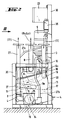
- numeral 1 indicates W.C. toilet bowls installed on board a ship. Each toilet bowl 1 is, through a normally-closed sewer valve la, connected to a sewer pipe 2, that is kept under partial vacuum and at its downstream end, by means of an end tube 3 and a check valve 10, communicates with a collecting container 4.
- the number of toilet bowls in a system according to the invention is usually at the most 60. It is, however, from the point of view of functional reliability recommendable, that the number of toilet bowls is less than this, for example between 30 and 40, and that the system is so devised, that normally not very many toilet bowls will be flushed at the same time. If necessary, the system may be provided with some form of flush-preventing or flush-delaying means. Such restrictions and/or restrictive actions are necessary primarily because the power of the vacuum pump of the system is relatively small and the volume of the collecting container 4 is also relatively small. The total volume of the collecting container 4 may be only about 50 litres, but it could be larger than this. The total volume of the interior of the vacuum sewer pipes 2, 3 is typically about 400 ⁇ 100 litres.
- the partial vacuum and the pressure required in the vacuum sewer system illustrated is provided by a dry sliding-vane rotary pump 5, the suction side 5a of which is connected to the collecting container 4 via a check valve 7, a liquid separator 6 and tubes 6a and 18.
- the pressure side 5b of the sliding-vane pump 5 includes a remote-controlled three-way valve 22 and tubes 27a and 27 connected to the atmosphere.
- the partial vacuum generated by the pump 5 in the sewer system 2, 3 and in the collecting container 4 is usually about 50% of the atmospheric pressure.
- the suction side 5a of the pump 5 is, through a remote-controlled three-way valve 21, connected to the atmosphere.
- the inflow of ambient air is represented by the arrow 21a and the pressure side 5b of the pump 5 is connected, through the remote-controlled three-way valve 22 and through the tube 6a, to the collecting container 4.
- the pressure generated by the pump 5 then acts on the sewage 17, because the pressure cannot escape through the check valve 10.
- the tube 9 operates as a separating device due to the fact that matter heavier than air, because of the action of centrifugal force, is moved to that side of the curved tube 9 that is outwards from its centre of curvature, while air present with the plug finds its way to the side of the curved tube 9 facing its centre of curvature. That side of the tube 9 is contacting the container 4 and is provided with apertures 12 through which the air is discharged into the collecting container 4. Finally, the sewage plug, flowing now rather slowly, passes into the collecting container 4 mainly tangentially through an outlet opening 9a marking the end of the tube 9.
- the sewer pipes 2 leading from the toilet bowls 1 communicate with the end tube 3, in which there is provided a U-shaped curve 19 forming a liquid-collecting trap.
- a U-shaped curve 19 forming a liquid-collecting trap.
- this trap at least a part of any liquid remaining in the sewer pipe is collected, forming there a liquid plug, which ensures that each sewage discharge which passes into the curved tube 9 includes a liquid plug.
- the level of sewage 17 preferably does not rise to above half the depth of the collecting container 4 so that sewage can enter the container 4 without excessive splashing, because the apertures 12 and 9a of the separating device created by the tube 9 are always above the sewage level.
- a level monitor 16 is provided in the collecting container 4 that monitors the amount of sewage 17 present.
- the sliding-vane pump 5 generates air flows, when partial vacuum is generated as well as when pressure is generated, in the container 4.
- the air guide pipe 18 at the collecting container end of the tube 6a these air flows are led along the surface of the level monitor 16, whereby the monitor is cleaned of matter that might possibly stick to it.
- the liquid separator 6 shown only schematically, forces the air flow flowing through it to the pump 5 to make several sharp changes in flow direction, whereby, because of the action of centrifugal force, any liquid drops present are separated from the air.
- the velocity of the air flow through the separating means 6 is also essentially slowed down at the points, where the cross-sectional area of the flow duct is large, which also is likely to cause a separating out of water drops flowing with the air.
- the separated liquid flows through the lower part of the tube 6a back to the collecting container 4. If the collecting container 4, in the case of a disturbance, is filled up totally, in other words to such a high level that the liquid level rises up to the device 6, a float 24 present therein closes the connection to the upper part of the pipe 6a. This prevents the liquid from rising higher than the device 6.
- the cylindrical collecting container 4 has in the embodiment illustrated a slightly oblique disposition, so that its longitudinal axis 13 forms an angle A to the vertical. This ensures the inlet end 14 of the outlet tube 8 of the collecting container 4 is in close vicinity to the lowest part 15 of the obliquely mounted collecting container 4. This gives the advantage that the collecting container is effectively completely emptied, only an extremely small amount of sewage remaining therein at the point 15, following a full emptying operation.
- a collecting and separating device 25 for, for example, condensed liquid is shown connected to the lower end of the mainly vertical tube 27. Any liquid collected in the device 25 is, in a known manner by means of partial vacuum, led through a pump 27b to the sewer 3 and therethrough to the collecting container 4.
- the device 25 one may use technical solutions of the kind shown in US-A-4057076, US-A-4280528, SE-B-398654 or GB-A-1312601.
- the operation of the vacuum sewer system and the tube and valve system is monitored and controlled by a control centre 23, receiving, through electric cables 26, data relating to the operational conditions of the different units of the system. Some of this data is provided by a pressure controlled relay 35 connected via a tube 33 to the sewer 3 downstream of the check valve 10 or directly to the container 4. Also shown is a pressure gauge 34 connected in parallel with the relay 35.
- Figures 2 and 3 show how the component parts of a system according to the invention, in other words the parts 3-29 and 33-35 of Figure 1 may be arranged in a prefabricated module having a frame 30 for mounting the described equipment and for fixing the component parts in place.
- a mounting module of this kind can be designed to be so compact that it requires a floor area of less than 0.5 m2.
Landscapes
- Engineering & Computer Science (AREA)
- Water Supply & Treatment (AREA)
- Health & Medical Sciences (AREA)
- Life Sciences & Earth Sciences (AREA)
- Hydrology & Water Resources (AREA)
- Public Health (AREA)
- Aviation & Aerospace Engineering (AREA)
- Chemical & Material Sciences (AREA)
- Combustion & Propulsion (AREA)
- Mechanical Engineering (AREA)
- Ocean & Marine Engineering (AREA)
- Sanitary Device For Flush Toilet (AREA)
- Sewage (AREA)
Applications Claiming Priority (2)
| Application Number | Priority Date | Filing Date | Title |
|---|---|---|---|
| FI934126 | 1993-09-21 | ||
| FI934126A FI93667C (fi) | 1993-09-21 | 1993-09-21 | Alipaineviemärilaite |
Publications (3)
| Publication Number | Publication Date |
|---|---|
| EP0644299A2 true EP0644299A2 (fr) | 1995-03-22 |
| EP0644299A3 EP0644299A3 (fr) | 1995-08-02 |
| EP0644299B1 EP0644299B1 (fr) | 1998-12-02 |
Family
ID=8538629
Family Applications (1)
| Application Number | Title | Priority Date | Filing Date |
|---|---|---|---|
| EP94306817A Expired - Lifetime EP0644299B1 (fr) | 1993-09-21 | 1994-09-19 | Système et procédé d'égout sous vide |
Country Status (11)
| Country | Link |
|---|---|
| US (1) | US5644802A (fr) |
| EP (1) | EP0644299B1 (fr) |
| JP (1) | JPH07196078A (fr) |
| KR (1) | KR100408869B1 (fr) |
| CA (1) | CA2132362A1 (fr) |
| DE (1) | DE69414949T2 (fr) |
| ES (1) | ES2125415T3 (fr) |
| FI (1) | FI93667C (fr) |
| NO (1) | NO943490L (fr) |
| PL (1) | PL175550B1 (fr) |
| SG (1) | SG48342A1 (fr) |
Cited By (5)
| Publication number | Priority date | Publication date | Assignee | Title |
|---|---|---|---|---|
| EP0937830A3 (fr) * | 1998-02-19 | 2000-02-02 | ROEDIGER VAKUUM- und HAUSTECHNIK GmbH | Système de vidange par aspiration ou évacuation |
| EP1270832A1 (fr) * | 2001-06-29 | 2003-01-02 | Evac International Oy | Système d'évacuation sous vide d'eaux usées |
| WO2012112838A1 (fr) * | 2011-02-17 | 2012-08-23 | The White Oak Partnership, Lp | Appareil et procédé d'accroissement de la capacité hydraulique d'un égout existant |
| US8381324B2 (en) | 2006-12-21 | 2013-02-26 | Evac International Oy | Vacuum sewage system |
| AT525155A1 (de) * | 2021-06-14 | 2022-12-15 | Eoos Next Gmbh | Vakuumtoilette sowie ein Vakuumtank für eine Vakuumtoilette |
Families Citing this family (24)
| Publication number | Priority date | Publication date | Assignee | Title |
|---|---|---|---|---|
| FI108937B (sv) * | 1999-03-10 | 2002-04-30 | Evac Int Oy | Vakuumtoalettanordning |
| US6152160A (en) * | 1999-08-30 | 2000-11-28 | Evac International Oy | Modular vacuum drainage system |
| KR100307179B1 (ko) * | 1999-10-07 | 2001-09-26 | 이영순 | 반지제조방법 |
| FI111289B (fi) * | 2000-07-10 | 2003-06-30 | Evac Int Oy | Alipainejärjestelmä |
| WO2002006594A1 (fr) * | 2000-07-17 | 2002-01-24 | Evac International Oy | Système de toilette à aspiration pour véhicules |
| FI20001759A0 (fi) * | 2000-08-07 | 2000-08-07 | Evac Int Oy | Alipaineviemärijärjestelmä |
| US6453481B1 (en) * | 2001-03-20 | 2002-09-24 | Evac International Oy | Vacuum waste system having a vacuum control valve |
| US6673135B2 (en) * | 2002-02-08 | 2004-01-06 | National Tank Company | System and method of separating entrained immiscible liquid component of an inlet stream |
| US20040135356A1 (en) * | 2002-06-28 | 2004-07-15 | Nobuyuki Katsuda | Air bag apparatus |
| KR20040001571A (ko) * | 2002-06-28 | 2004-01-07 | 선진환경기공주식회사 | 분뇨 수거 설비 및 그의 자동 운전방법 |
| ITPD20030015U1 (it) * | 2003-03-04 | 2004-09-05 | Cappellotto Spa | Impianto perfezionato per la creazione del vuoto all'interno di serbatoi di accumulo spurgo |
| US7373946B2 (en) * | 2004-10-22 | 2008-05-20 | Dometic Sanitation Corporation | Vacuum tank assembly |
| EP1752589A1 (fr) * | 2005-08-12 | 2007-02-14 | Glova GmbH | Une toilette sous vide |
| US7998250B2 (en) * | 2008-10-03 | 2011-08-16 | B/E Aerospace, Inc. | Multiple vortex waste separator apparatus |
| US7998251B2 (en) * | 2008-10-03 | 2011-08-16 | B/E Aerospace, Inc. | Vortex waste separator apparatus |
| CN201512849U (zh) * | 2009-09-24 | 2010-06-23 | 山东华腾环保科技有限公司 | 真空辅助便器 |
| US8228190B2 (en) * | 2010-02-24 | 2012-07-24 | Data Flow Systems, Inc. | Valve malfunctioning detection system for a vacuum sewer an associated methods |
| US8490223B2 (en) | 2011-08-16 | 2013-07-23 | Flow Control LLC | Toilet with ball valve mechanism and secondary aerobic chamber |
| BR112015020338A2 (pt) * | 2013-03-05 | 2017-08-22 | Maricap Oy | Método para o enchimento de um dispositivo de contenção/separação de rejeitos de um sistema pneumático de transporte de materiais, equipamento para o enchimento de um dispositivo de contenção/separação de rejeitos de um sistema pneumático de transporte de materiais, dispositivos de contenção/separação de rejeitos para sistemas pneumáticos de transporte de materiais |
| KR101464481B1 (ko) | 2013-10-22 | 2014-11-27 | 주식회사 호두 | 진공변기시스템의 자동배출장치 |
| DE202013011431U1 (de) * | 2013-12-20 | 2015-03-23 | Evac Gmbh | Vakuumtoilette mit Fliehkraftabscheider |
| KR101514930B1 (ko) * | 2014-11-10 | 2015-04-24 | 주식회사 호두 | 안전성이 강화된 진공변기시스템용 자동배출장치 |
| CN106379357A (zh) * | 2016-09-29 | 2017-02-08 | 青岛轶骋铁路真空系统制造有限公司 | 一种带有分离器的真空保持式集便系统 |
| CN109680781B (zh) * | 2018-12-29 | 2020-08-07 | 重庆工程职业技术学院 | 装配式建筑外挂墙板排水结构 |
Citations (5)
| Publication number | Priority date | Publication date | Assignee | Title |
|---|---|---|---|---|
| US3956776A (en) * | 1975-05-28 | 1976-05-18 | Thetford Corporation | Liquid waste material conveying system for toilets and the like |
| US4332041A (en) * | 1980-11-24 | 1982-06-01 | The Boeing Company | Pressurized drain for toilet waste tank |
| US4521925A (en) * | 1982-06-30 | 1985-06-11 | The Boeing Company | Nonrecirculating vacuum flush toilet system utilizing fresh water |
| DE8421675U1 (de) * | 1984-07-20 | 1985-11-14 | Feluwa Schlesiger & Co KG, 5531 Mürlenbach | Arbeitsbehälter für eine Saug- bzw. Druckvorrichtung einer Flüssigkeit-Förderanlage |
| EP0386449A2 (fr) * | 1989-03-10 | 1990-09-12 | Bavaria Keytronic Technologie Gmbh | Toilette pour aéronef |
Family Cites Families (6)
| Publication number | Priority date | Publication date | Assignee | Title |
|---|---|---|---|---|
| SE389882B (sv) * | 1975-04-23 | 1976-11-22 | Ifoe Ab | Anordning vid vakuumklosett med uppsamlingsbehallare |
| US4963094A (en) * | 1987-04-13 | 1990-10-16 | Ramvac Corp. | Vacuum controller and filter assembly for dental vacuum system |
| US4819279A (en) * | 1987-09-28 | 1989-04-11 | Sealand Technology, Inc. | Vacuum toilet system |
| US4865631A (en) * | 1988-02-26 | 1989-09-12 | Oy Wartsila Ab | Vacuum sewage system |
| US5002592A (en) * | 1988-02-26 | 1991-03-26 | Oy Wartsila Ab | Waste tank for a vacuum sewage system |
| SE501960C2 (sv) * | 1990-04-20 | 1995-06-26 | Waertsilae Oy Ab | Vakuumtoalettsystem med vakuumgenerator med väsentligen konstant drifttid |
-
1993
- 1993-09-21 FI FI934126A patent/FI93667C/fi active
-
1994
- 1994-09-19 DE DE69414949T patent/DE69414949T2/de not_active Expired - Fee Related
- 1994-09-19 SG SG1996009023A patent/SG48342A1/en unknown
- 1994-09-19 EP EP94306817A patent/EP0644299B1/fr not_active Expired - Lifetime
- 1994-09-19 ES ES94306817T patent/ES2125415T3/es not_active Expired - Lifetime
- 1994-09-19 CA CA002132362A patent/CA2132362A1/fr not_active Abandoned
- 1994-09-20 JP JP6224600A patent/JPH07196078A/ja active Pending
- 1994-09-20 NO NO943490A patent/NO943490L/no not_active Application Discontinuation
- 1994-09-21 PL PL94305126A patent/PL175550B1/pl unknown
- 1994-09-22 KR KR1019940023851A patent/KR100408869B1/ko not_active IP Right Cessation
-
1996
- 1996-08-20 US US08/700,125 patent/US5644802A/en not_active Expired - Fee Related
Patent Citations (5)
| Publication number | Priority date | Publication date | Assignee | Title |
|---|---|---|---|---|
| US3956776A (en) * | 1975-05-28 | 1976-05-18 | Thetford Corporation | Liquid waste material conveying system for toilets and the like |
| US4332041A (en) * | 1980-11-24 | 1982-06-01 | The Boeing Company | Pressurized drain for toilet waste tank |
| US4521925A (en) * | 1982-06-30 | 1985-06-11 | The Boeing Company | Nonrecirculating vacuum flush toilet system utilizing fresh water |
| DE8421675U1 (de) * | 1984-07-20 | 1985-11-14 | Feluwa Schlesiger & Co KG, 5531 Mürlenbach | Arbeitsbehälter für eine Saug- bzw. Druckvorrichtung einer Flüssigkeit-Förderanlage |
| EP0386449A2 (fr) * | 1989-03-10 | 1990-09-12 | Bavaria Keytronic Technologie Gmbh | Toilette pour aéronef |
Cited By (7)
| Publication number | Priority date | Publication date | Assignee | Title |
|---|---|---|---|---|
| EP0937830A3 (fr) * | 1998-02-19 | 2000-02-02 | ROEDIGER VAKUUM- und HAUSTECHNIK GmbH | Système de vidange par aspiration ou évacuation |
| EP1270832A1 (fr) * | 2001-06-29 | 2003-01-02 | Evac International Oy | Système d'évacuation sous vide d'eaux usées |
| US8381324B2 (en) | 2006-12-21 | 2013-02-26 | Evac International Oy | Vacuum sewage system |
| WO2012112838A1 (fr) * | 2011-02-17 | 2012-08-23 | The White Oak Partnership, Lp | Appareil et procédé d'accroissement de la capacité hydraulique d'un égout existant |
| US9157226B2 (en) | 2011-02-17 | 2015-10-13 | The White Oak Partnership Lp | Apparatus and method for increasing hydraulic capacity of a sewer |
| AT525155A1 (de) * | 2021-06-14 | 2022-12-15 | Eoos Next Gmbh | Vakuumtoilette sowie ein Vakuumtank für eine Vakuumtoilette |
| AT525155B1 (de) * | 2021-06-14 | 2023-02-15 | Eoos Next Gmbh | Vakuumtoilette sowie ein Vakuumtank für eine Vakuumtoilette |
Also Published As
| Publication number | Publication date |
|---|---|
| KR100408869B1 (ko) | 2004-03-06 |
| ES2125415T3 (es) | 1999-03-01 |
| NO943490L (no) | 1995-03-22 |
| KR950008873A (ko) | 1995-04-19 |
| NO943490D0 (no) | 1994-09-20 |
| SG48342A1 (en) | 1998-04-17 |
| US5644802A (en) | 1997-07-08 |
| EP0644299A3 (fr) | 1995-08-02 |
| FI934126A0 (fi) | 1993-09-21 |
| JPH07196078A (ja) | 1995-08-01 |
| PL305126A1 (en) | 1995-04-03 |
| CA2132362A1 (fr) | 1995-03-22 |
| FI93667B (fi) | 1995-01-31 |
| EP0644299B1 (fr) | 1998-12-02 |
| FI93667C (fi) | 1995-05-10 |
| DE69414949T2 (de) | 1999-04-22 |
| PL175550B1 (pl) | 1999-01-29 |
| DE69414949D1 (de) | 1999-01-14 |
Similar Documents
| Publication | Publication Date | Title |
|---|---|---|
| EP0644299B1 (fr) | Système et procédé d'égout sous vide | |
| AU2007336150B2 (en) | Vacuum sewage system | |
| EP0363012B1 (fr) | Système de toilette à vide | |
| FI60273C (fi) | Undertrycks-avloppsanlaeggning foer byggnader | |
| CN202893538U (zh) | 真空排污系统及其旋流分离装置 | |
| KR20180110097A (ko) | 변기 구조물 | |
| US5538546A (en) | Waste tank for vacuum sewage system | |
| CA2352596A1 (fr) | Systeme d'egout a vide | |
| EP0287350A2 (fr) | Système sous vide pour recueillir des eaux usées | |
| JP2684526B2 (ja) | 真空式汚水集排水装置と真空式下水道 | |
| EP1291468A2 (fr) | Systeme d'evacuation a vide equipe d'une citerne d'eaux residuelles de retenue temporelle | |
| FI72955B (fi) | Anlaeggning foer avloppsvattenbehandling. | |
| AU668795B2 (en) | Waste tank for vacuum sewage system | |
| CA2209661C (fr) | Reservoir d'eaux usees destine a un systeme de confinement d'eaux usees par vide d'air | |
| US5284507A (en) | Waste tank for vacuum sewage system | |
| JP2002194807A (ja) | 真空式下水道 | |
| EP1105588A1 (fr) | Procede et systeme permettant d'evacuer un flux residuaire et siphon associe | |
| BE901775A (nl) | Inrichting voor het verwijderen van afvalwater van een voor de wal liggend schip. | |
| KR200433504Y1 (ko) | 하수도용 관거 세척장치 | |
| KR100749915B1 (ko) | 하수도용 관거 세척장치 | |
| JPH08145218A (ja) | 真空式汚水集排水用タンクの排気弁装置 | |
| AU7209200A (en) | Waste tank for vacuum sewage system | |
| HU194343B (en) | Sewage disposal apparatus | |
| JP2003034974A (ja) | 真空集排水ステーション及びその真空集排水方法 |
Legal Events
| Date | Code | Title | Description |
|---|---|---|---|
| PUAI | Public reference made under article 153(3) epc to a published international application that has entered the european phase |
Free format text: ORIGINAL CODE: 0009012 |
|
| AK | Designated contracting states |
Kind code of ref document: A2 Designated state(s): DE ES GB GR NL |
|
| PUAL | Search report despatched |
Free format text: ORIGINAL CODE: 0009013 |
|
| AK | Designated contracting states |
Kind code of ref document: A3 Designated state(s): DE ES GB GR NL |
|
| 17P | Request for examination filed |
Effective date: 19951208 |
|
| 17Q | First examination report despatched |
Effective date: 19970414 |
|
| GRAG | Despatch of communication of intention to grant |
Free format text: ORIGINAL CODE: EPIDOS AGRA |
|
| GRAG | Despatch of communication of intention to grant |
Free format text: ORIGINAL CODE: EPIDOS AGRA |
|
| GRAH | Despatch of communication of intention to grant a patent |
Free format text: ORIGINAL CODE: EPIDOS IGRA |
|
| GRAH | Despatch of communication of intention to grant a patent |
Free format text: ORIGINAL CODE: EPIDOS IGRA |
|
| GRAA | (expected) grant |
Free format text: ORIGINAL CODE: 0009210 |
|
| AK | Designated contracting states |
Kind code of ref document: B1 Designated state(s): DE ES GB GR NL |
|
| REF | Corresponds to: |
Ref document number: 69414949 Country of ref document: DE Date of ref document: 19990114 |
|
| REG | Reference to a national code |
Ref country code: ES Ref legal event code: FG2A Ref document number: 2125415 Country of ref document: ES Kind code of ref document: T3 |
|
| PLBE | No opposition filed within time limit |
Free format text: ORIGINAL CODE: 0009261 |
|
| STAA | Information on the status of an ep patent application or granted ep patent |
Free format text: STATUS: NO OPPOSITION FILED WITHIN TIME LIMIT |
|
| 26N | No opposition filed | ||
| REG | Reference to a national code |
Ref country code: GB Ref legal event code: IF02 |
|
| PGFP | Annual fee paid to national office [announced via postgrant information from national office to epo] |
Ref country code: NL Payment date: 20020815 Year of fee payment: 9 |
|
| PGFP | Annual fee paid to national office [announced via postgrant information from national office to epo] |
Ref country code: GR Payment date: 20020822 Year of fee payment: 9 |
|
| PGFP | Annual fee paid to national office [announced via postgrant information from national office to epo] |
Ref country code: ES Payment date: 20020909 Year of fee payment: 9 |
|
| PGFP | Annual fee paid to national office [announced via postgrant information from national office to epo] |
Ref country code: GB Payment date: 20030815 Year of fee payment: 10 |
|
| PGFP | Annual fee paid to national office [announced via postgrant information from national office to epo] |
Ref country code: DE Payment date: 20030821 Year of fee payment: 10 |
|
| PG25 | Lapsed in a contracting state [announced via postgrant information from national office to epo] |
Ref country code: ES Free format text: LAPSE BECAUSE OF NON-PAYMENT OF DUE FEES Effective date: 20030920 |
|
| PG25 | Lapsed in a contracting state [announced via postgrant information from national office to epo] |
Ref country code: NL Free format text: LAPSE BECAUSE OF NON-PAYMENT OF DUE FEES Effective date: 20040401 |
|
| PG25 | Lapsed in a contracting state [announced via postgrant information from national office to epo] |
Ref country code: GR Free format text: LAPSE BECAUSE OF NON-PAYMENT OF DUE FEES Effective date: 20040402 |
|
| NLV4 | Nl: lapsed or anulled due to non-payment of the annual fee |
Effective date: 20040401 |
|
| PG25 | Lapsed in a contracting state [announced via postgrant information from national office to epo] |
Ref country code: GB Free format text: LAPSE BECAUSE OF NON-PAYMENT OF DUE FEES Effective date: 20040919 |
|
| REG | Reference to a national code |
Ref country code: ES Ref legal event code: FD2A Effective date: 20030920 |
|
| PG25 | Lapsed in a contracting state [announced via postgrant information from national office to epo] |
Ref country code: DE Free format text: LAPSE BECAUSE OF NON-PAYMENT OF DUE FEES Effective date: 20050401 |
|
| GBPC | Gb: european patent ceased through non-payment of renewal fee |
Effective date: 20040919 |