EP0643429A2 - Boîtier à piles avec interconnexion câblée minimale pour ordinateur portable - Google Patents
Boîtier à piles avec interconnexion câblée minimale pour ordinateur portable Download PDFInfo
- Publication number
- EP0643429A2 EP0643429A2 EP94306648A EP94306648A EP0643429A2 EP 0643429 A2 EP0643429 A2 EP 0643429A2 EP 94306648 A EP94306648 A EP 94306648A EP 94306648 A EP94306648 A EP 94306648A EP 0643429 A2 EP0643429 A2 EP 0643429A2
- Authority
- EP
- European Patent Office
- Prior art keywords
- circuit board
- printed circuit
- battery pack
- batteries
- housing
- Prior art date
- Legal status (The legal status is an assumption and is not a legal conclusion. Google has not performed a legal analysis and makes no representation as to the accuracy of the status listed.)
- Withdrawn
Links
Images

Classifications
-
- G—PHYSICS
- G06—COMPUTING; CALCULATING OR COUNTING
- G06F—ELECTRIC DIGITAL DATA PROCESSING
- G06F1/00—Details not covered by groups G06F3/00 - G06F13/00 and G06F21/00
- G06F1/16—Constructional details or arrangements
- G06F1/1613—Constructional details or arrangements for portable computers
-
- G—PHYSICS
- G06—COMPUTING; CALCULATING OR COUNTING
- G06F—ELECTRIC DIGITAL DATA PROCESSING
- G06F1/00—Details not covered by groups G06F3/00 - G06F13/00 and G06F21/00
- G06F1/16—Constructional details or arrangements
- G06F1/1613—Constructional details or arrangements for portable computers
- G06F1/1633—Constructional details or arrangements of portable computers not specific to the type of enclosures covered by groups G06F1/1615 - G06F1/1626
- G06F1/1635—Details related to the integration of battery packs and other power supplies such as fuel cells or integrated AC adapter
-
- H—ELECTRICITY
- H01—ELECTRIC ELEMENTS
- H01M—PROCESSES OR MEANS, e.g. BATTERIES, FOR THE DIRECT CONVERSION OF CHEMICAL ENERGY INTO ELECTRICAL ENERGY
- H01M50/00—Constructional details or processes of manufacture of the non-active parts of electrochemical cells other than fuel cells, e.g. hybrid cells
- H01M50/20—Mountings; Secondary casings or frames; Racks, modules or packs; Suspension devices; Shock absorbers; Transport or carrying devices; Holders
- H01M50/204—Racks, modules or packs for multiple batteries or multiple cells
- H01M50/207—Racks, modules or packs for multiple batteries or multiple cells characterised by their shape
- H01M50/213—Racks, modules or packs for multiple batteries or multiple cells characterised by their shape adapted for cells having curved cross-section, e.g. round or elliptic
-
- Y—GENERAL TAGGING OF NEW TECHNOLOGICAL DEVELOPMENTS; GENERAL TAGGING OF CROSS-SECTIONAL TECHNOLOGIES SPANNING OVER SEVERAL SECTIONS OF THE IPC; TECHNICAL SUBJECTS COVERED BY FORMER USPC CROSS-REFERENCE ART COLLECTIONS [XRACs] AND DIGESTS
- Y02—TECHNOLOGIES OR APPLICATIONS FOR MITIGATION OR ADAPTATION AGAINST CLIMATE CHANGE
- Y02E—REDUCTION OF GREENHOUSE GAS [GHG] EMISSIONS, RELATED TO ENERGY GENERATION, TRANSMISSION OR DISTRIBUTION
- Y02E60/00—Enabling technologies; Technologies with a potential or indirect contribution to GHG emissions mitigation
- Y02E60/10—Energy storage using batteries
Definitions
- the present invention relates to a battery pack for a portable computer wherein the battery pack has a minimum number of hard wire connections.
- Hard wiring various circuits within the battery pack is expensive and time-consuming since all of the hard wiring must be done by hand.
- the combination of hand soldering and hand installation adds significant additional manpower to manufacture of such battery packs.
- the necessity of hard wiring within a battery pack adds additional space to the overall battery pack housing in order to mount such hard wiring within the battery pack housing.
- the battery pack of this invention includes a generally rectangular housing which includes a bottom having an opening therein.
- the housing is sized to receive a plurality of batteries for providing power to the portable computer.
- a support chassis is mounted with the housing and includes a plurality of mounting slots, which mounting slots receive individual, electrical contacts.
- the support chassis is mounted over the opening in the bottom of the housing such that the electrical contacts are aligned with the housing bottom opening and are thus exposed for making electrical contact with circuitry of the main computer housing.
- a printed circuit board is attached to the support chassis.
- the printed circuit board includes a plurality of openings.
- the electrical contacts mounted in the support chassis mounting slots include tabbed end portions which extend through the openings in the printed circuit board in order to be electrically connected to the electronic components located on the printed circuit board.
- Hard wiring is necessary only to electrically connect the positive and negative terminal ends of the battery set within the battery pack housing. In this manner, a battery pack is provided which substantially minimizes the amount of hard wiring and instead provides electrical contacts mounted within a modular chassis for making electrical contact to the main computer housing.
- the letter P generally designates the battery pack of the preferred embodiment of this invention.
- the battery pack P is specifically designed for use in a portable or notebook computer but has application in equivalent power systems.
- the battery pack P includes a generally rectangular, box-like housing 10 which includes a bottom 10a having formed therewith four sidewalls including side walls 10b and 10c which intersect to form a corner 10d.
- the housing 10 further includes a third sidewall which opposes sidewall 10b and a fourth sidewall which opposes sidewall 10c, neither of which is illustrated in the drawings but is easily understood as within the ordinary skill of the art.
- the upstanding sidewalls including sidewalls 10b and 10c are integrally formed with the bottom and cooperate to provide a generally rectangular box-like interior space to receive a plurality of batteries generally designated as B (Fig. 2).
- the housing 10 further includes a top or lid 10e which is generally rectangular in configuration and is sized to fit onto the four sidewalls such as 10b and 10c of the housing 10.
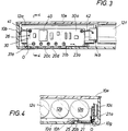
- a rectangular opening O is located in the bottom 10a of the housing 10.
- the opening O is formed by side edges 10g, 10h, 10i and 10j. Referring to Fig. 4, side opening edge 10h is slightly indented.
- the batteries B are actually an array which are serially connected to provide the necessary voltage. Although not all batteries are shown, the batteries preferably utilized in this invention are 1.2-volt nickel metal hydride batteries connected in series to provide a total voltage of 12 volts. Referring to Fig. 2, batteries 12a, 12b, 12c, 12d, 12e and 12f are illustrated. The serial connection between batteries is provided by a series of conducting contact strips such as illustrated at 14 as is well known in the art. Battery 12a includes a first terminal contact strip 14a and battery 12f includes a terminal contact strip 14b to the series connection of the batteries together. In addition and not shown, one or more fuses may be hard wired between various terminals of the batteries to act as circuit breakers or permanent disconnects in the event of power surges, shorts and the like.
- a support chassis generally designated as 20 is provided for mounting within the battery housing 10 in the opening O in order to provide a wireless electrical interface between the batteries B, a printed circuit board generally designated as 30 and the main computer housing (not shown).
- the support chassis 20 includes a generally rectangular plate member designated as 20a.
- the plate member 20a includes a plurality of aligned openings 20b which cooperate with a second set of aligned openings 20c to provide mounting shoulders for a plurality of metal conducting strips or contacts 21.
- the outer face of the rectangular mounting plate 20a includes a plurality of ridges such as 20c and 20d which cooperate to receive the individually mounted electrical contacts or strips 21.
- each electrical contact or strip 21 includes internally directed shoulders which are inserted into the openings 20b and 20c in order to snap the contacts into place in slots formed by the external ridges such as 20c and 20d.
- Each electrical contact or conductive strip 21 further includes an inverted, T-shaped tab portion 21a.
- Each of the inverted T-shaped tab portions 21a extend through openings at 31a and 31b in the base 30a of the printed circuit board 30.
- the tabs 21a for each of the five electrical contacts illustrated in the drawings extend through the openings at 31a and 31b in the base 30 for the printed circuit board and are soldered into place as illustrated in Fig. 3 (the actual openings in the base being filled by the solder as illustrated in Fig. 3).
- a generally U-shaped opening 22 cooperates with a node 22a to mount a thermistor element 23.
- the thermistor element 23 includes two terminal end portions, one of which being identified as 23a, which extend through openings in the base 30a of the printed circuit board 30 and are soldered in place.
- the soldered joints such as 31a and 31b and the terminated end portions such as 23a of the thermistor 23 are electronically connected to the various electronic components generally designated as 40 mounted on the printed circuit board base 30a.
- the thermistor is a temperature sensor which generates temperature dependent signals which are utilized in the various circuits of the electrical components to, among other things, timely re-charge the batteries.
- the location of the thermistor element 23 is such that it is in close proximity to the batteries B when the batteries B are installed in the housing 10, allowing the thermistor element 23 to accurately sense the temperature of the batteries B.
- the chassis plate 20a further includes two laterally extending pedestals or ledges such as 24 which mount the printed circuit board base 30a thereon such that the printed circuit board base 30a is at a right angle with respect to the internal flat surface of the chassis support plate 20a.
- Each of the pedestals 24 include an outwardly extending node such as 26 which has an enlarged end and extends through an opening in the printed circuit board face so that upon snapping the opening over the enlarged end of the node 26, the printed circuit board 30 is attached to the pedestals or ledges 24 of the overall chassis 20.
- the chassis plate 20a further includes a stepped mounting ledge generally designated as 25 for mounting the chassis in the opening O in the battery pack housing bottom.
- the chassis 20 is actually mounted in place from inside of the housing by first inserting the mounting ledge or lip 25 over the indented bottom opening edge 10h and then rotating the chassis into a frictional fit in the remainder of the opening 0.
- the printed circuit board 30 is provided to electronically interface between the batteries B and the main computer housing through the electrical contacts 21 which are exposed through the opening O in the bottom of the battery pack.
- the utilization of the five electrical contact surfaces of points 21 to interface with the main computer housing eliminates the necessity of hard wiring those contact points thereby reducing expense and labour in the manufacture of the battery pack P.
- the printed circuit board 30 includes the electronics generally designated as 40 to perform whatever necessary electronic functions are needed to properly maintain and recharge the array of batteries B.
- One version of such electronics is found in EP-A-0 577 810 entitled “Battery Charge Monitor and Fuel Gauge" and EP-A-0 616 281 entitled “Battery Pack Including Static Memory and a Timer For Charged Management". Since the electronic components mounted on the printed circuit board do not form part of this invention, there is no need for further description of the components themselves.
- the combination of the chassis 20 and printed circuit board 30 in cooperation of the array of batteries B provide for a substantially wireless connection between the host computer and the battery pack. Further, the positioning of the chassis 20 in the opening O in the bottom of the battery pack places the chassis in an unobtrusive relationship with the actual bottom 10a of the housing such that the chassis takes up minimal space within the confines of the housing. Further, the utilization of the pedestals such as 24 to mount the printed circuit board 30 at a right angle to the chassis base plate 20a allows the printed circuit board to be positioned adjacent the upright side wall 10c once again mounting the components in a highly efficient manner within the confines of the battery pack housing. This efficient mounting of the chassis 20 and printed circuit board 30a in cooperation with the utilization of the series of electrical contacts 21 provide a wireless, compact battery power and electronic transfer unit for portable and notebook computers.
Landscapes
- Engineering & Computer Science (AREA)
- Theoretical Computer Science (AREA)
- Computer Hardware Design (AREA)
- General Physics & Mathematics (AREA)
- Physics & Mathematics (AREA)
- General Engineering & Computer Science (AREA)
- Human Computer Interaction (AREA)
- Power Engineering (AREA)
- Chemical & Material Sciences (AREA)
- Chemical Kinetics & Catalysis (AREA)
- Electrochemistry (AREA)
- General Chemical & Material Sciences (AREA)
- Battery Mounting, Suspending (AREA)
Applications Claiming Priority (2)
| Application Number | Priority Date | Filing Date | Title |
|---|---|---|---|
| US119426 | 1993-09-10 | ||
| US08/119,426 US5459388A (en) | 1993-09-10 | 1993-09-10 | Battery pack with minimum hard wiring connection for portable computer |
Publications (2)
| Publication Number | Publication Date |
|---|---|
| EP0643429A2 true EP0643429A2 (fr) | 1995-03-15 |
| EP0643429A3 EP0643429A3 (fr) | 1995-09-06 |
Family
ID=22384359
Family Applications (1)
| Application Number | Title | Priority Date | Filing Date |
|---|---|---|---|
| EP94306648A Withdrawn EP0643429A3 (fr) | 1993-09-10 | 1994-09-09 | Boîtier à piles avec interconnexion câblée minimale pour ordinateur portable. |
Country Status (4)
| Country | Link |
|---|---|
| US (1) | US5459388A (fr) |
| EP (1) | EP0643429A3 (fr) |
| JP (1) | JP2769982B2 (fr) |
| CA (1) | CA2131213A1 (fr) |
Cited By (5)
| Publication number | Priority date | Publication date | Assignee | Title |
|---|---|---|---|---|
| EP0694980A2 (fr) * | 1994-07-29 | 1996-01-31 | International Business Machines Corporation | Paquet de batterie et mécanisme interconnexion |
| EP0739049A1 (fr) * | 1995-04-18 | 1996-10-23 | International Business Machines Corporation | Paquet de batteries |
| WO1999005731A1 (fr) * | 1997-07-25 | 1999-02-04 | Minnesota Mining And Manufacturing Company | Module de stockage d'energie transistorise a carte d'interconnexion integree |
| EP0906853A3 (fr) * | 1997-10-03 | 2000-06-28 | Lear Automotive Dearborn, Inc. | Boite de jonction montée sur la batterie |
| EP1630889A1 (fr) * | 2004-06-30 | 2006-03-01 | Tyco Electronics Nederland B.V. | Bouchon pour une batterie d'un appareil électronique mobile |
Families Citing this family (18)
| Publication number | Priority date | Publication date | Assignee | Title |
|---|---|---|---|---|
| US5621299A (en) * | 1994-01-27 | 1997-04-15 | David A. Krall | Rechargeable battery power supply with load voltage sensing, selectable output voltage and a wrist rest |
| US5898290A (en) * | 1995-09-07 | 1999-04-27 | Norand Corporation | Battery pack with capacity and pre-removal indicators |
| US5736271A (en) * | 1996-06-28 | 1998-04-07 | Telxon Corporation | Battery pack for portable electronic device |
| US6224996B1 (en) * | 1998-08-21 | 2001-05-01 | Compaq Computer Corporation | Battery housing wall interweave with all of system enclosure to reduce height of portable computer |
| JP3454748B2 (ja) * | 1999-02-26 | 2003-10-06 | 三洋電機株式会社 | パック電池 |
| US6326767B1 (en) | 1999-03-30 | 2001-12-04 | Shoot The Moon Products Ii, Llc | Rechargeable battery pack charging system with redundant safety systems |
| US7609027B2 (en) | 2001-11-09 | 2009-10-27 | Milwaukee Electric Tool Corporation | Electrical component, audio component, or electrical combination having a selectively connectable battery charger |
| US7149482B2 (en) * | 2003-09-16 | 2006-12-12 | Andrew Corporation | Compensation of filters in radio transmitters |
| US8604752B2 (en) | 2003-10-14 | 2013-12-10 | Robert Bosch Gmbh | Portable battery charging and audio unit |
| US7835534B2 (en) | 2003-10-14 | 2010-11-16 | Robert Bosch Gmbh | Battery charging jobsite lunchbox |
| US20050271934A1 (en) * | 2004-06-05 | 2005-12-08 | Kiger William B | Battery pack assembly |
| JP4991122B2 (ja) * | 2005-04-18 | 2012-08-01 | 株式会社東芝 | 電子機器 |
| US7741809B2 (en) | 2006-01-06 | 2010-06-22 | Milwaukee Electric Tool Corporation | Electrical component including a battery receptacle for including a battery |
| US8287185B2 (en) * | 2009-10-01 | 2012-10-16 | Delphi Technologies, Inc. | Cell temperature sensing apparatus for a battery module |
| JP2013157291A (ja) * | 2012-01-31 | 2013-08-15 | Toshiba Corp | バッテリユニットを含む構造及び電子機器 |
| US10439196B2 (en) | 2015-12-18 | 2019-10-08 | Bourns, Inc. | Electromechanical circuit breaker |
| EP3811441B1 (fr) | 2018-06-22 | 2023-06-07 | Bourns, Inc. | Disjoncteurs |
| EP4022662A4 (fr) | 2019-08-27 | 2023-10-25 | Bourns, Inc. | Connecteur doté d'un dispositif de coupure thermique intégré pour bloc-batterie |
Citations (3)
| Publication number | Priority date | Publication date | Assignee | Title |
|---|---|---|---|---|
| GB2249865A (en) * | 1990-10-25 | 1992-05-20 | Triumph Adler Ag | Power supply pack comprising rechargeable batteries in a foamed plastics body, for portable electrical devices |
| US5122927A (en) * | 1989-10-31 | 1992-06-16 | Kabushiki Kaisha Toshiba | Portable electronic apparatus having terminal supported from the bottom case for electrically connecting optional part to the apparatus and method of assembling the same |
| US5248927A (en) * | 1991-03-18 | 1993-09-28 | Sony Corporation | Battery pack with temperature detecting element and battery charger therefor |
Family Cites Families (19)
| Publication number | Priority date | Publication date | Assignee | Title |
|---|---|---|---|---|
| US4481458A (en) * | 1983-04-11 | 1984-11-06 | Levitt-Safety Limited | Miners lamp power pack |
| US4647832A (en) * | 1984-07-26 | 1987-03-03 | Pittway Corporation | Three position switch for portable, rechargeable device |
| US4670701A (en) * | 1984-11-19 | 1987-06-02 | Matsushita Electric Industrial Co., Ltd. | Rechargeable cordless vacuum cleaner apparatus |
| US4680527A (en) * | 1986-08-06 | 1987-07-14 | Motorola, Inc. | Electrical battery including apparatus for current sensing |
| JPH0747957Y2 (ja) * | 1987-03-31 | 1995-11-01 | トツパン・ム−ア株式会社 | 非接触式電力供給装置 |
| US5164652A (en) * | 1989-04-21 | 1992-11-17 | Motorola, Inc. | Method and apparatus for determining battery type and modifying operating characteristics |
| US5193220A (en) * | 1989-06-02 | 1993-03-09 | Nec Corporation | Device for mounting an electronic part |
| JP2736128B2 (ja) * | 1989-09-20 | 1998-04-02 | 株式会社東芝 | 無線通信装置 |
| US5001772A (en) * | 1989-11-17 | 1991-03-19 | Jack N. Holcomb | Power pack with concealed radio transmitter for portable cellular telephone |
| US5111128A (en) * | 1990-12-17 | 1992-05-05 | Motorola, Inc. | Battery identification apparatus |
| JP2545123Y2 (ja) * | 1991-02-20 | 1997-08-25 | 三洋電機株式会社 | 電池パック |
| US5151643A (en) * | 1991-03-04 | 1992-09-29 | Motorola, Inc. | Integral hang-up and battery charging apparatus |
| US5307519A (en) * | 1992-03-02 | 1994-04-26 | Motorola, Inc. | Circuit with built-in heat sink |
| US5180644A (en) * | 1992-03-09 | 1993-01-19 | Motorola, Inc. | Weldless battery pack |
| US5242767A (en) * | 1992-06-22 | 1993-09-07 | Motorola, Inc. | Battery housing assembly with integral limited travel guide rails |
| US5223780A (en) * | 1992-07-14 | 1993-06-29 | Stephen Hu | Mobile telephone battery power supply unit with power detection and discharge circuit |
| US5245269A (en) * | 1992-08-17 | 1993-09-14 | Ncr Corporation | Battery temperature sensing apparatus |
| US5298347A (en) * | 1992-09-14 | 1994-03-29 | Motorola, Inc. | Battery pack |
| GB2273226B (en) * | 1992-12-01 | 1997-03-26 | Nokia Mobile Phones Uk | A battery pack |
-
1993
- 1993-09-10 US US08/119,426 patent/US5459388A/en not_active Expired - Lifetime
-
1994
- 1994-08-31 CA CA002131213A patent/CA2131213A1/fr not_active Abandoned
- 1994-09-09 JP JP6242026A patent/JP2769982B2/ja not_active Expired - Fee Related
- 1994-09-09 EP EP94306648A patent/EP0643429A3/fr not_active Withdrawn
Patent Citations (3)
| Publication number | Priority date | Publication date | Assignee | Title |
|---|---|---|---|---|
| US5122927A (en) * | 1989-10-31 | 1992-06-16 | Kabushiki Kaisha Toshiba | Portable electronic apparatus having terminal supported from the bottom case for electrically connecting optional part to the apparatus and method of assembling the same |
| GB2249865A (en) * | 1990-10-25 | 1992-05-20 | Triumph Adler Ag | Power supply pack comprising rechargeable batteries in a foamed plastics body, for portable electrical devices |
| US5248927A (en) * | 1991-03-18 | 1993-09-28 | Sony Corporation | Battery pack with temperature detecting element and battery charger therefor |
Cited By (8)
| Publication number | Priority date | Publication date | Assignee | Title |
|---|---|---|---|---|
| EP0694980A2 (fr) * | 1994-07-29 | 1996-01-31 | International Business Machines Corporation | Paquet de batterie et mécanisme interconnexion |
| EP0694980A3 (fr) * | 1994-07-29 | 1996-05-01 | Ibm | Paquet de batterie et mécanisme interconnexion |
| EP0739049A1 (fr) * | 1995-04-18 | 1996-10-23 | International Business Machines Corporation | Paquet de batteries |
| US5818198A (en) * | 1995-04-18 | 1998-10-06 | International Business Machines Corp. | Battery pack |
| WO1999005731A1 (fr) * | 1997-07-25 | 1999-02-04 | Minnesota Mining And Manufacturing Company | Module de stockage d'energie transistorise a carte d'interconnexion integree |
| US6146778A (en) * | 1997-07-25 | 2000-11-14 | 3M Innovative Properties Company | Solid-state energy storage module employing integrated interconnect board |
| EP0906853A3 (fr) * | 1997-10-03 | 2000-06-28 | Lear Automotive Dearborn, Inc. | Boite de jonction montée sur la batterie |
| EP1630889A1 (fr) * | 2004-06-30 | 2006-03-01 | Tyco Electronics Nederland B.V. | Bouchon pour une batterie d'un appareil électronique mobile |
Also Published As
| Publication number | Publication date |
|---|---|
| US5459388A (en) | 1995-10-17 |
| CA2131213A1 (fr) | 1995-03-11 |
| JPH07153437A (ja) | 1995-06-16 |
| JP2769982B2 (ja) | 1998-06-25 |
| EP0643429A3 (fr) | 1995-09-06 |
Similar Documents
| Publication | Publication Date | Title |
|---|---|---|
| US5459388A (en) | Battery pack with minimum hard wiring connection for portable computer | |
| JP4910170B2 (ja) | 通信ポートを備えたバッテリーパック | |
| US5225760A (en) | Rechargeable power pack | |
| US20020182480A1 (en) | Electrical energy storage pack | |
| US20220223949A1 (en) | Battery pack and electric device | |
| US5679017A (en) | Universal battery charger | |
| EP1225646A1 (fr) | Unité de batterie assemblées et sa méthode de fabrication | |
| JPH0794232A (ja) | 電池用電気コネクタ | |
| JPS6359226B2 (fr) | ||
| EP0617486A1 (fr) | Connecteur pour batterie | |
| EP0545132B1 (fr) | Bloc d'alimentation rechargeable | |
| US6464512B2 (en) | Apparatus with spring-loaded contacts | |
| JPH08236215A (ja) | カード受入コネクタのための万能接地クリップ | |
| EP0694980A2 (fr) | Paquet de batterie et mécanisme interconnexion | |
| US8216706B2 (en) | Battery pack | |
| US5920178A (en) | Battery pack having integrated charging circuit and charging connector and method of forming same | |
| US4622274A (en) | Battery terminal | |
| JPH0512515A (ja) | 電池およびこの電池を用いたicカード | |
| EP0601711A1 (fr) | Paquet de batteries | |
| US5403203A (en) | Contact array | |
| CN114069164A (zh) | 电池连接模块 | |
| US20020076580A1 (en) | Interlocking cell constructions | |
| US5995375A (en) | Cell holder unit and electronic device using such | |
| JPH1012201A (ja) | プリント基板を内蔵するパック電池 | |
| KR200247738Y1 (ko) | 양면 장착이 가능한 배터리 팩 |
Legal Events
| Date | Code | Title | Description |
|---|---|---|---|
| PUAI | Public reference made under article 153(3) epc to a published international application that has entered the european phase |
Free format text: ORIGINAL CODE: 0009012 |
|
| AK | Designated contracting states |
Kind code of ref document: A2 Designated state(s): AT BE CH DE DK ES FR GB GR IE IT LI LU MC NL PT SE |
|
| RAX | Requested extension states of the european patent have changed |
Free format text: LT PAYMENT 941111;SI PAYMENT 941111 |
|
| PUAL | Search report despatched |
Free format text: ORIGINAL CODE: 0009013 |
|
| AK | Designated contracting states |
Kind code of ref document: A3 Designated state(s): AT BE CH DE DK ES FR GB GR IE IT LI LU MC NL PT SE |
|
| 17P | Request for examination filed |
Effective date: 19960223 |
|
| STAA | Information on the status of an ep patent application or granted ep patent |
Free format text: STATUS: THE APPLICATION HAS BEEN WITHDRAWN |
|
| 18W | Application withdrawn |
Withdrawal date: 19960607 |