EP0642882A1 - Echangeur de palettes pour machine-outil - Google Patents
Echangeur de palettes pour machine-outil Download PDFInfo
- Publication number
- EP0642882A1 EP0642882A1 EP94109772A EP94109772A EP0642882A1 EP 0642882 A1 EP0642882 A1 EP 0642882A1 EP 94109772 A EP94109772 A EP 94109772A EP 94109772 A EP94109772 A EP 94109772A EP 0642882 A1 EP0642882 A1 EP 0642882A1
- Authority
- EP
- European Patent Office
- Prior art keywords
- pallet
- bridge table
- rocker
- guides
- rack
- Prior art date
- Legal status (The legal status is an assumption and is not a legal conclusion. Google has not performed a legal analysis and makes no representation as to the accuracy of the status listed.)
- Granted
Links
Images


Classifications
-
- B—PERFORMING OPERATIONS; TRANSPORTING
- B23—MACHINE TOOLS; METAL-WORKING NOT OTHERWISE PROVIDED FOR
- B23Q—DETAILS, COMPONENTS, OR ACCESSORIES FOR MACHINE TOOLS, e.g. ARRANGEMENTS FOR COPYING OR CONTROLLING; MACHINE TOOLS IN GENERAL CHARACTERISED BY THE CONSTRUCTION OF PARTICULAR DETAILS OR COMPONENTS; COMBINATIONS OR ASSOCIATIONS OF METAL-WORKING MACHINES, NOT DIRECTED TO A PARTICULAR RESULT
- B23Q7/00—Arrangements for handling work specially combined with or arranged in, or specially adapted for use in connection with, machine tools, e.g. for conveying, loading, positioning, discharging, sorting
- B23Q7/14—Arrangements for handling work specially combined with or arranged in, or specially adapted for use in connection with, machine tools, e.g. for conveying, loading, positioning, discharging, sorting co-ordinated in production lines
- B23Q7/1426—Arrangements for handling work specially combined with or arranged in, or specially adapted for use in connection with, machine tools, e.g. for conveying, loading, positioning, discharging, sorting co-ordinated in production lines with work holders not rigidly fixed to the transport devices
- B23Q7/1431—Work holder changers
-
- Y—GENERAL TAGGING OF NEW TECHNOLOGICAL DEVELOPMENTS; GENERAL TAGGING OF CROSS-SECTIONAL TECHNOLOGIES SPANNING OVER SEVERAL SECTIONS OF THE IPC; TECHNICAL SUBJECTS COVERED BY FORMER USPC CROSS-REFERENCE ART COLLECTIONS [XRACs] AND DIGESTS
- Y10—TECHNICAL SUBJECTS COVERED BY FORMER USPC
- Y10T—TECHNICAL SUBJECTS COVERED BY FORMER US CLASSIFICATION
- Y10T29/00—Metal working
- Y10T29/51—Plural diverse manufacturing apparatus including means for metal shaping or assembling
- Y10T29/5196—Multiple station with conveyor
Definitions
- the invention relates to a pallet changer for machine tools according to the preamble of claim 1.
- a pallet changer of this type is known from EP 0 281 664 B1.
- a pallet receptacle is slidably mounted in the X direction on a slide which can be displaced in the Y direction.
- a rocker is pivotally mounted on the pallet holder about an axis perpendicular to the XY plane.
- a gear wheel attached to the axis of the rocker engages in a toothed rack attached to the slide in order to pivot the rocker when the pallet holder is moved in the X direction on the slide.
- the rocker engages with a roller attached to its free end in a groove of the pallet in order to move the pallet during the pivoting movement of the rocker.
- the pallet holder is used to change the pallet hydraulically lifted to axially move the rocker gear and engage the rack.
- the pallet holder is then shifted in the X direction, whereby the pallet is pushed at a higher speed in the X direction from the pallet holder in accordance with the radius ratio of the rocker and gear.
- the slide is moved in the Y direction in order to bring the rocker into engagement with its roller with a pallet with unmachined workpieces that is in a waiting position B.
- the pallet holder is then pushed back in the X direction, the rocker being pivoted back and pushing the pallet with the unprocessed workpieces onto the pallet holder.
- the pallet is tensioned and indexed by lowering the pallet holder.
- the pallet changer pushes the pallet from the pallet holder into an immediately adjacent first waiting position and picks up the pallets from a likewise immediately adjacent second waiting position, the two waiting positions being arranged next to one another in a common plane.
- the spatial separation of the waiting positions from the work area of the machine tools is insufficient.
- the need for two waiting positions placed next to each other on the same level affects the flexibility in the construction of the machine tool and in the possible uses of a pallet store.
- the pallet change requires movements of the pallet holder in two axes, namely the X and Y directions, so that the pallet changer is not suitable for machine tools, such as machining centers, in which the pallet holder can only be displaced in one spatial axis, while the movement in the other two spatial axes is carried out by the tool.
- the invention has for its object to provide a pallet changer that enables a change of the pallets with short idle times with a pallet holder that can only be moved in one spatial direction and that is flexible in the connection to the pallet feeder.
- the pallet receptacle is mounted in a slide that can only be displaced in one spatial axis.
- the movement of the slide is used to pivot the rocker, the rocker pushing the pallet perpendicular to the axis of movement of the slide from the pallet holder.
- a bridge table is taken in synchronism with the displacement of the slide, so that the pallet can be pushed from the pallet holder onto the bridge table during the movement of the slide.
- the bridge table is held so that the pallet of the Bridge table can be pushed into the transfer station, for which the slide is moved further and the rocker swings further.
- the transfer of the pallet to the bridge table and the transfer of the pallet from the bridge table to the transfer station enable the transfer station to be at a greater distance from the working area of the machine tool in which the pallet holder of the slide is located.
- the transfer station can be a station of a pallet store or a linking system, so that there is a high degree of flexibility in the use of the machine tool and its pallet feed.
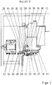
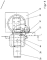
- the pallet changer is shown in connection with a machining center in which the workpiece table can be moved vertically on a stand with a horizontal axis (X axis) and the tool spindle is mounted horizontally in a spindle box which is in the two horizontal Axes (Y-axis and Z-axis) can be moved.
- a carriage 14 can be moved on the stand 10 in vertical guide rails 12.
- the carriage 14 is driven by an electric motor via a spindle 16.
- a rotary table or rotary indexing table with a horizontal axis is rotatably mounted in the slide 14.
- the rotary table or rotary indexing table has a plate 18, on the end face of which a pallet holder 20 is attached.
- the pallet holder 20 has pallet guides 22 and a pallet indexing.
- the pallet guides 22 are equipped with ball-bearing rollers and are used in a known manner for receiving standardized interchangeable pallets.
- a rack 24 is attached, which is vertically parallel to the guide rails 12 runs, adjoins the slide 14 laterally and extends upwards from the lower end position of the slide 14.
- the toothing of the rack 24 faces the carriage 14.
- a vertical bridge guide rail 26 is attached to the vertical end face of the stand 10 and is located on the side of the rack 24 facing away from the slide 14.
- a bridge table 28 is vertically displaceable.
- the bridge table 28 carries, on its vertical end face, horizontally arranged pallet guides 30 which are designed corresponding to the pallet guides 22 of the pallet receptacle 20.
- a second vertical toothed rack 32 is fastened to the bridge table 28 and is arranged on the end face in front of the toothed rack 24.
- the toothings of the toothed racks 24 and 32 match in tooth shape and tooth pitch and are arranged such that they come to coincide with one another when the toothed rack 32 is in a corresponding vertical position.
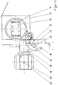
- a driver roller 34 is rotatably mounted on the bridge table 28 about a horizontal axis. The driver roller 34 is arranged on the front side of the bridge table 28 in front of the rack 32, as can be seen from FIG.
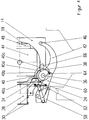
- a shaft 36 with a horizontal axis perpendicular to the plane of the slide 14 is rotatably mounted in the slide 14.
- a gear 38 sits on the end of the shaft 36 facing the stator 10, the toothing of which extends over approximately 2/3 of the circumference.
- the toothing of the gear wheel 38 corresponds to the toothing of the toothed racks 24 and 32.
- the axial width and the axial arrangement of the gear wheel 38 are chosen so that its teeth can engage with the racks 24 and 32.
- a driver cam 40 is also mounted in a rotationally fixed manner on the shaft 36, the outer circumference of which can come into contact with the driver roller 34 of the bridge table 28.
- a crescent-shaped rocker 42 sits on the shaft 36 in a rotationally fixed manner.
- the pivoting plane of the rocker 42 lies directly on the front side in front of the vertical end face of the slide 14.
- the rocker 42 is located outside a pallet 44 arranged on the pallet holder 20 Swing arm 42 has at its free end a roller 46 which is rotatable about a horizontal axis and is seated on the side of the swing arm 42 facing away from the slide 14.
- the pallets 44 have on their one end face perpendicular to the direction of the pallet guides 22 on the underside a groove 48, in which the roller 46 of the rocker 42 can engage.
- a transfer station 50 is arranged to the side of the stand 10, which in the exemplary embodiment shown is a station of a pallet store.
- the transfer station 50 also has horizontally arranged pallet guides 52 for the standardized pallets 44.
- a door 54 that can be lowered vertically closes off the work space of the machining center.
- the door 54 lowers between the slide 14 with the pallet holder 20 and the bridge table 28.
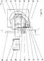
- the door 54 is raised and lowered by means of a fluid cylinder, the piston rod 56 of which is shown in FIG. 3.
- the door 54 presses a first lever 58 downward, which in turn takes a second lever 60 downward against the force of a prestressed spring 62 attached to the stand.
- a roller 64 is mounted, which can come into engagement with the gear 38.
- the rocker 42 is under its own weight in an end position in which its roller 46 is located outside the pallet 44.
- the carriage 14 is first moved into its lowest position shown in FIG.
- the entire device takes the position shown in Figure 3.
- the door 54 closing the work space is now opened upwards.
- the stop of the door 54 lifts off the first lever 58 and releases it.
- the preloaded spring 62 can now pull the second lever 60 upward (clockwise in the drawing).
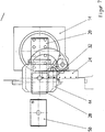
- the roller 64 of the second lever 60 is pressed under the force of the spring 62 against the tooth flank of the first tooth of the gear 38, as shown in FIG. 4.
- the rocker 42 is thereby pivoted counterclockwise out of its basic position, the driver curve 40 comes free from the stop 66 and the gear 38 comes with its last tooth in the counterclockwise direction into engagement with the stationary rack 24. This situation is shown in FIG.
- the bridge table 28 is taken synchronously with the carriage 14 and moved upwards on its bridge guide rail 26, since its driving roller 34 concentric on the Circumferential portion 40b of the driver curve 40 is supported.
- the rocker 42 is pivoted further counterclockwise and thereby pushes the pallet 44 (to the left in the drawing) from the pallet guides 22 of the pallet receptacle 20 onto the pallet guides 30 of the bridge table 28.
- This displacement is possible during the movement of the slide 14, since the bridge table 28 moves together with the slide 14, thereby the pallet guides 22 of the pallet receptacle 20 and the pallet guides 30 of the bridge table 28 always remain in alignment.
- the crescent-shaped design of the rocker 42 ensures that the rocker 42 is guided around the lower right corner of the pallet 44 during this pivoting movement and that the pallet 44 does not hinder the movement of the rocker 42. This situation is shown in Figure 6.
- the pallet guides 30 of the bridge table 28 and the pallet guides 52 of the transfer station 50 are exactly aligned, the pallet 44 is completely open pushed the bridge table 28 and released from the pallet guides 22 of the pallet receptacle 20.
- the entraining curve 40 has rotated so far that its concentric circumferential section 40b is turned away under the entraining roller 34 and the entraining roller 34 comes to rest against an essentially radial section 40c of the entraining curve 40.
- the course of the radial section 40c of the driver curve 40 is selected such that when the carriage 14 moves further upward, the driver roller 34 is not pushed upward further and the bridge table 28 maintains its vertical position in which its pallet guides 30 with the pallet guides 52 the transfer station 50 are aligned. Since the bridge table 28 is no longer moved upward, the toothed rack 32 attached to the bridge table 28 also stops and the toothed wheel 38 now also comes into engagement with this toothed rack 32. This situation is shown in Figure 8.
- the carriage 14 is moved upward.
- the rocker 42 pushes the pallet 44 from the bridge table 28 completely onto the pallet guides 52 of the transfer station 50.
- the driver roller 34 is located in the region of the undercut section 40d of the driver curve 40 and is thus free from the driver curve 40 and is no longer supported by it.
- the movement of the carriage 14 upwards no longer takes the bridge table 28 with it.
- the gear 38 meshes with both the rack 24 fixed to the stand and with the rack 32 fastened to the bridge table 28.
- the racks 24 and 32 are thereby held by means of the gear 38 with congruent teeth and the bridge table 28 is in relation to the stand 10 in the Fixed position in which its pallet guides 30 are aligned with the pallet guides 52 of the transfer station 50. This situation is shown in Figure 10.
- the pallet store can be switched on, so that the transferred pallet 44 with the machined workpieces is moved out of the transfer station 50 and a new pallet with unworked workpieces reaches the transfer station 50.
- the carriage 14 is then moved down again, the rocker 42 being pivoted counterclockwise via the gear 38 meshing with the rack 24.
- the roller 46 of the rocker 42 enters from below into the groove 48 of the pallet 44, which is now in the transfer station 50.
Applications Claiming Priority (2)
| Application Number | Priority Date | Filing Date | Title |
|---|---|---|---|
| DE4330915A DE4330915C1 (de) | 1993-09-11 | 1993-09-11 | Palettenwechsler für Werkzeugmaschinen |
| DE4330915 | 1993-09-11 |
Publications (2)
| Publication Number | Publication Date |
|---|---|
| EP0642882A1 true EP0642882A1 (fr) | 1995-03-15 |
| EP0642882B1 EP0642882B1 (fr) | 1996-10-23 |
Family
ID=6497509
Family Applications (1)
| Application Number | Title | Priority Date | Filing Date |
|---|---|---|---|
| EP94109772A Expired - Lifetime EP0642882B1 (fr) | 1993-09-11 | 1994-06-24 | Echangeur de palettes pour machine-outil |
Country Status (4)
| Country | Link |
|---|---|
| US (1) | US5454149A (fr) |
| EP (1) | EP0642882B1 (fr) |
| AT (1) | ATE144451T1 (fr) |
| DE (1) | DE4330915C1 (fr) |
Cited By (1)
| Publication number | Priority date | Publication date | Assignee | Title |
|---|---|---|---|---|
| DE10204327A1 (de) * | 2002-02-01 | 2003-08-14 | Grob Werke Burkhart Grob Ek | Palettenwechselsystem |
Families Citing this family (6)
| Publication number | Priority date | Publication date | Assignee | Title |
|---|---|---|---|---|
| DE19533975A1 (de) * | 1995-09-14 | 1997-03-20 | Merck Patent Gmbh | Arylalkyl-diazinone |
| JP3361769B2 (ja) * | 1999-02-22 | 2003-01-07 | 安田工業株式会社 | 工作機械用のパレット交換装置 |
| US6464066B2 (en) * | 2000-04-04 | 2002-10-15 | Inno-Veyor, Inc. | Conveyor assembly with pallet coupling |
| US20040182680A1 (en) * | 2003-03-21 | 2004-09-23 | Hinrich Stave | Pallet changing system |
| US7575789B2 (en) * | 2003-12-17 | 2009-08-18 | E.I. Du Pont De Nemours And Company | Coated pipes for conveying oil |
| CN106335779A (zh) * | 2016-08-26 | 2017-01-18 | 江苏大学 | 一种具有急回特性的新型推进机构 |
Citations (7)
| Publication number | Priority date | Publication date | Assignee | Title |
|---|---|---|---|---|
| EP0000874A1 (fr) * | 1977-08-24 | 1979-03-07 | KEARNEY & TRECKER CORPORATION | Machine-outil avec entrainement commun pour la table et pour le transporteur des pallets |
| DD201987A5 (de) * | 1981-01-21 | 1983-08-24 | Gerhard Stark | Werkzeugmaschine mit werkstueckzufuehrorganen |
| JPS60131146A (ja) * | 1983-12-19 | 1985-07-12 | Toyoda Mach Works Ltd | パレツト交換装置 |
| DE3605470A1 (de) * | 1985-02-25 | 1986-08-28 | Yamazaki Machinery Works, Ltd., Ooguchi, Aichi | Mehrflaechenbearbeitungs-werkzeugmaschine |
| EP0366791A1 (fr) * | 1987-06-19 | 1990-05-09 | Kitamura Machinery Co., Ltd. | Echangeur de palettes |
| EP0281664B1 (fr) * | 1987-02-23 | 1992-10-28 | Matsuura Machinery Corporation | Dispositif de changement de palette pour machine-outil |
| DE4236416A1 (fr) * | 1991-11-20 | 1993-05-27 | Brother Ind Ltd |
Family Cites Families (5)
| Publication number | Priority date | Publication date | Assignee | Title |
|---|---|---|---|---|
| DE201987C (fr) * | ||||
| SU620420A2 (ru) * | 1977-02-24 | 1978-08-25 | Всесоюзный Научно-Исследовательский Технологический Институт Приборостроения | Приспособление к конвейеру дл подачи спутников с издели ми к месту их обработки |
| JPS6021156Y2 (ja) * | 1980-09-05 | 1985-06-24 | 株式會社牧野フライス製作所 | 数値制御工作機械のパレット交換装置 |
| JPH0657376B2 (ja) * | 1985-12-28 | 1994-08-03 | 津田駒工業株式会社 | パレツト交換装置 |
| JP3259333B2 (ja) * | 1992-06-12 | 2002-02-25 | 豊田工機株式会社 | パレット交換装置 |
-
1993
- 1993-09-11 DE DE4330915A patent/DE4330915C1/de not_active Expired - Fee Related
-
1994
- 1994-06-24 EP EP94109772A patent/EP0642882B1/fr not_active Expired - Lifetime
- 1994-06-24 AT AT94109772T patent/ATE144451T1/de not_active IP Right Cessation
- 1994-08-25 US US08/296,108 patent/US5454149A/en not_active Expired - Fee Related
Patent Citations (7)
| Publication number | Priority date | Publication date | Assignee | Title |
|---|---|---|---|---|
| EP0000874A1 (fr) * | 1977-08-24 | 1979-03-07 | KEARNEY & TRECKER CORPORATION | Machine-outil avec entrainement commun pour la table et pour le transporteur des pallets |
| DD201987A5 (de) * | 1981-01-21 | 1983-08-24 | Gerhard Stark | Werkzeugmaschine mit werkstueckzufuehrorganen |
| JPS60131146A (ja) * | 1983-12-19 | 1985-07-12 | Toyoda Mach Works Ltd | パレツト交換装置 |
| DE3605470A1 (de) * | 1985-02-25 | 1986-08-28 | Yamazaki Machinery Works, Ltd., Ooguchi, Aichi | Mehrflaechenbearbeitungs-werkzeugmaschine |
| EP0281664B1 (fr) * | 1987-02-23 | 1992-10-28 | Matsuura Machinery Corporation | Dispositif de changement de palette pour machine-outil |
| EP0366791A1 (fr) * | 1987-06-19 | 1990-05-09 | Kitamura Machinery Co., Ltd. | Echangeur de palettes |
| DE4236416A1 (fr) * | 1991-11-20 | 1993-05-27 | Brother Ind Ltd |
Non-Patent Citations (1)
| Title |
|---|
| PATENT ABSTRACTS OF JAPAN vol. 9, no. 290 (M - 430)<2013> 16 November 1985 (1985-11-16) * |
Cited By (1)
| Publication number | Priority date | Publication date | Assignee | Title |
|---|---|---|---|---|
| DE10204327A1 (de) * | 2002-02-01 | 2003-08-14 | Grob Werke Burkhart Grob Ek | Palettenwechselsystem |
Also Published As
| Publication number | Publication date |
|---|---|
| ATE144451T1 (de) | 1996-11-15 |
| DE4330915C1 (de) | 1994-09-08 |
| US5454149A (en) | 1995-10-03 |
| EP0642882B1 (fr) | 1996-10-23 |
Similar Documents
| Publication | Publication Date | Title |
|---|---|---|
| DE1552408C3 (de) | Werkzeugmaschine mit einer automatischen Werkzeug-Wechselvorrichtung | |
| EP0343552B1 (fr) | Presse à découper avec un outil de découpage échangeable et avancement de pièce à travailler | |
| DE3240911C2 (fr) | ||
| EP0247168B1 (fr) | Dispositif de table rotative a mouvement vertical | |
| DE3536323C2 (de) | Stanz-Gewindebohrmaschine | |
| EP1982799A1 (fr) | Agencement de manipulation | |
| DE3017613C2 (fr) | ||
| EP0901848B1 (fr) | Presse de transfert avec changement d' outil automatique | |
| DE4232497C2 (de) | Vorrichtung zur Positionierung einer Karosserie auf einem Förderer | |
| DE1640520A1 (de) | Automatische Einrichtung zum Aufbringen von elektrischen Schaltungsmustern auf Traegerplatten | |
| DE3241844C1 (de) | Stanzmaschine mit Revolvertrommel | |
| EP0642882B1 (fr) | Echangeur de palettes pour machine-outil | |
| DE19500652C1 (de) | Handhabungsvorrichtung für eine Werkzeugmaschine | |
| DE2733482A1 (de) | Automatische werkzeugwechseleinrichtung | |
| DE3323502C1 (de) | Revolver-Drehautomat | |
| DE3101765C2 (de) | Werkzeugmaschine mit Werkstückzuführorganen | |
| EP0342257A1 (fr) | Machine-outil à magasin et changeur d'outils | |
| DE19545570A1 (de) | Transfereinrichtung für Mehrstationenpressen | |
| DE4421624C2 (de) | Werkzeugwechseleinrichtung für eine Universal-Bearbeitungsmaschine | |
| EP0847832B1 (fr) | Fraiseuse-aléseuse universelle | |
| DE2933491C2 (de) | Transfermaschine | |
| DE3826827C2 (de) | Vorrichtung zum Positionieren einer Blechtafel | |
| DE1402921B2 (de) | Doppelspindel drehmaschine | |
| DE4111547A1 (de) | Rundtaktautomat | |
| DE1802629C3 (de) | Vorrichtung zum Überführen von Werkstücken zwischen aufeinanderfolgenden Bearbeitungsstationen an Pressen und dergleichen Werkzeugmaschinen |
Legal Events
| Date | Code | Title | Description |
|---|---|---|---|
| PUAI | Public reference made under article 153(3) epc to a published international application that has entered the european phase |
Free format text: ORIGINAL CODE: 0009012 |
|
| AK | Designated contracting states |
Kind code of ref document: A1 Designated state(s): AT BE CH ES FR GB IT LI LU NL SE |
|
| 17P | Request for examination filed |
Effective date: 19950511 |
|
| 17Q | First examination report despatched |
Effective date: 19951017 |
|
| GRAH | Despatch of communication of intention to grant a patent |
Free format text: ORIGINAL CODE: EPIDOS IGRA |
|
| GRAH | Despatch of communication of intention to grant a patent |
Free format text: ORIGINAL CODE: EPIDOS IGRA |
|
| RBV | Designated contracting states (corrected) |
Designated state(s): AT BE CH ES FR GB IT LI LU NL SE |
|
| REG | Reference to a national code |
Ref country code: DE Ref legal event code: 8566 |
|
| GRAA | (expected) grant |
Free format text: ORIGINAL CODE: 0009210 |
|
| AK | Designated contracting states |
Kind code of ref document: B1 Designated state(s): AT BE CH ES FR GB IT LI LU NL SE |
|
| PG25 | Lapsed in a contracting state [announced via postgrant information from national office to epo] |
Ref country code: NL Free format text: LAPSE BECAUSE OF FAILURE TO SUBMIT A TRANSLATION OF THE DESCRIPTION OR TO PAY THE FEE WITHIN THE PRESCRIBED TIME-LIMIT Effective date: 19961023 Ref country code: IT Free format text: LAPSE BECAUSE OF FAILURE TO SUBMIT A TRANSLATION OF THE DESCRIPTION OR TO PAY THE FEE WITHIN THE PRE;WARNING: LAPSES OF ITALIAN PATENTS WITH EFFECTIVE DATE BEFORE 2007 MAY HAVE OCCURRED AT ANY TIME BEFORE 2007. THE CORRECT EFFECTIVE DATE MAY BE DIFFERENT FROM THE ONE RECORDED.SCRIBED TIME-LIMIT Effective date: 19961023 Ref country code: FR Effective date: 19961023 Ref country code: ES Free format text: THE PATENT HAS BEEN ANNULLED BY A DECISION OF A NATIONAL AUTHORITY Effective date: 19961023 |
|
| REF | Corresponds to: |
Ref document number: 144451 Country of ref document: AT Date of ref document: 19961115 Kind code of ref document: T |
|
| GBT | Gb: translation of ep patent filed (gb section 77(6)(a)/1977) |
Effective date: 19961024 |
|
| PG25 | Lapsed in a contracting state [announced via postgrant information from national office to epo] |
Ref country code: SE Effective date: 19970123 |
|
| EN | Fr: translation not filed | ||
| NLV1 | Nl: lapsed or annulled due to failure to fulfill the requirements of art. 29p and 29m of the patents act | ||
| PG25 | Lapsed in a contracting state [announced via postgrant information from national office to epo] |
Ref country code: AT Free format text: LAPSE BECAUSE OF NON-PAYMENT OF DUE FEES Effective date: 19970624 |
|
| PG25 | Lapsed in a contracting state [announced via postgrant information from national office to epo] |
Ref country code: LU Free format text: LAPSE BECAUSE OF NON-PAYMENT OF DUE FEES Effective date: 19970630 Ref country code: LI Free format text: LAPSE BECAUSE OF NON-PAYMENT OF DUE FEES Effective date: 19970630 Ref country code: CH Free format text: LAPSE BECAUSE OF NON-PAYMENT OF DUE FEES Effective date: 19970630 Ref country code: BE Effective date: 19970630 |
|
| PLBE | No opposition filed within time limit |
Free format text: ORIGINAL CODE: 0009261 |
|
| STAA | Information on the status of an ep patent application or granted ep patent |
Free format text: STATUS: NO OPPOSITION FILED WITHIN TIME LIMIT |
|
| 26N | No opposition filed | ||
| BERE | Be: lapsed |
Owner name: BERNHARD STEINEL WERKZEUGMASCHINENFABRIK G.M.B.H. Effective date: 19970630 |
|
| REG | Reference to a national code |
Ref country code: CH Ref legal event code: PL |
|
| PGFP | Annual fee paid to national office [announced via postgrant information from national office to epo] |
Ref country code: GB Payment date: 19980617 Year of fee payment: 5 |
|
| PG25 | Lapsed in a contracting state [announced via postgrant information from national office to epo] |
Ref country code: GB Free format text: LAPSE BECAUSE OF NON-PAYMENT OF DUE FEES Effective date: 19990624 |
|
| GBPC | Gb: european patent ceased through non-payment of renewal fee |
Effective date: 19990624 |