EP0639869A2 - Borne ou ramificateur serti, étanche, et anticorrosif - Google Patents
Borne ou ramificateur serti, étanche, et anticorrosif Download PDFInfo
- Publication number
- EP0639869A2 EP0639869A2 EP94306005A EP94306005A EP0639869A2 EP 0639869 A2 EP0639869 A2 EP 0639869A2 EP 94306005 A EP94306005 A EP 94306005A EP 94306005 A EP94306005 A EP 94306005A EP 0639869 A2 EP0639869 A2 EP 0639869A2
- Authority
- EP
- European Patent Office
- Prior art keywords
- barrel
- wire
- insert sleeve
- assembly
- housing
- Prior art date
- Legal status (The legal status is an assumption and is not a legal conclusion. Google has not performed a legal analysis and makes no representation as to the accuracy of the status listed.)
- Ceased
Links
Images


Classifications
-
- H—ELECTRICITY
- H01—ELECTRIC ELEMENTS
- H01R—ELECTRICALLY-CONDUCTIVE CONNECTIONS; STRUCTURAL ASSOCIATIONS OF A PLURALITY OF MUTUALLY-INSULATED ELECTRICAL CONNECTING ELEMENTS; COUPLING DEVICES; CURRENT COLLECTORS
- H01R4/00—Electrically-conductive connections between two or more conductive members in direct contact, i.e. touching one another; Means for effecting or maintaining such contact; Electrically-conductive connections having two or more spaced connecting locations for conductors and using contact members penetrating insulation
- H01R4/10—Electrically-conductive connections between two or more conductive members in direct contact, i.e. touching one another; Means for effecting or maintaining such contact; Electrically-conductive connections having two or more spaced connecting locations for conductors and using contact members penetrating insulation effected solely by twisting, wrapping, bending, crimping, or other permanent deformation
- H01R4/18—Electrically-conductive connections between two or more conductive members in direct contact, i.e. touching one another; Means for effecting or maintaining such contact; Electrically-conductive connections having two or more spaced connecting locations for conductors and using contact members penetrating insulation effected solely by twisting, wrapping, bending, crimping, or other permanent deformation by crimping
- H01R4/20—Electrically-conductive connections between two or more conductive members in direct contact, i.e. touching one another; Means for effecting or maintaining such contact; Electrically-conductive connections having two or more spaced connecting locations for conductors and using contact members penetrating insulation effected solely by twisting, wrapping, bending, crimping, or other permanent deformation by crimping using a crimping sleeve
- H01R4/203—Electrically-conductive connections between two or more conductive members in direct contact, i.e. touching one another; Means for effecting or maintaining such contact; Electrically-conductive connections having two or more spaced connecting locations for conductors and using contact members penetrating insulation effected solely by twisting, wrapping, bending, crimping, or other permanent deformation by crimping using a crimping sleeve having an uneven wire-receiving surface to improve the contact
Definitions
- the present invention relates to a sealed corrosion-proof crimped terminal (or splice) for aluminum or copper wire, and more particularly, to a terminal (or splice) having a perforated insert sleeve for facilitating the crimping process and improving the product resulting therefrom.
- Sealed terminals and splices are a type of connector used especially for terminating discrete aluminum and copper lead wires. These connectors terminate stranded aluminum and copper wire using a "dry crimp" process which eliminates the need for an inhibitor agent to break down oxides which form on the aluminum and copper wire strands. The dry crimp technique results in a sealed connection, thereby preventing re-oxidation and corrosion after crimping.
- a complete line of such high-quality copper sealed terminals and splices is supplied by AMP Incorporated of Harrisburg, Pennsylvania, U.S.A., under the registered trademark COPALUM®.
- U.S. Patent No. 3,955,044 discloses an insert sleeve positioned within the barrel portion of the terminal, and the strands of wire (such as aluminum wire) are received within the insert sleeve.
- the insert sleeve is formed from a material which has a hardness equal to or greater than that of the wire.
- the insert sleeve is a split cylindrical sleeve which is perforated. During the crimping process, the aluminum or copper wire extrudes through the perforations in the insert sleeve, thereby breaking down the aluminum or copper oxide film on the wire strands, increasing the surface contact areas, and facilitating good electrical contact with the terminal.
- the insert sleeve may tend to rotate prior to crimping due to twisting of the wire and, as a result, this may cause cracking of the terminal during the crimping process.
- the present invention finds particular utility in a crimped connector assembly (either for terminating an end of a wire or splicing the respective ends of two wires) wherein a housing has a hollow barrel provided with an open end, wherein an insert sleeve is received within the barrel, wherein the wire is received through the open end of the barrel and within the insert sleeve, and wherein the housing is crimped over the insert sleeve and the wire, thereby retaining the wire.
- a protruding lug is formed on the barrel, and the insert sleeve has a notch receiving the protruding lug on the barrel.
- the insert sleeve is circumferentially keyed to the barrel, thereby preventing relative rotation therebetween, improving heat dissipation, and reinforcing the housing and the insert sleeve when the housing is crimped over the insert sleeve and the wire.
- the housing has an interior wall adjacent to the hollow barrel, and the insert sleeve abuts against this interior wall.
- the lug protrudes axially from the interior wall of the housing, radially inwardly of the barrel, and in the direction of the open end thereof.
- a tapered insertion ring is disposed within the barrel for guiding the wire therein, and the barrel has an internal annular indentation rearwardly of the tapered insertion ring and substantially adjacent thereto, thereby retaining the tapered insertion ring.
- this tapered insertion ring is formed from a plastic material.
- an insertion funnel may be provided as an accessory to facilitate the insertion of the strands of wire (or wires) into the open end of the barrel portion of the housing.
- a crimping assembly for a wire wherein a housing has a hollow barrel provided with an open end, an insert sleeve is received within the barrel, the wire is received through the open end of the barrel and within the insert sleeve, and the housing is crimped over the insert sleeve and the wire, thereby retaining the wire, the barrel includes a protruding lug, and the insert sleeve has a notch receiving the protruding lug on the barrel, thereby circumferentially keying the insert sleeve to the barrel and preventing relative rotation therebetween.
- FIG. 1 is a perspective view of a prior art terminal assembly shown fully assembled and crimped.
- FIG. 2 is a perspective view of the prior art terminal assembly of FIG. 1, showing the discrete components thereof in exploded relationship prior to the crimping operation.
- FIG. 3 is a further exploded perspective view, corresponding substantially to that of FIG. 2, but showing the improvement of the present invention.
- FIG. 4 is a bottom cut-away view of the splice housing used in the assembly of FIG. 3.
- FIG. 5 is a longitudinal cross-sectional view of the splice assembly of FIG. 3 prior to the crimping process (the other insert sleeve being omitted for convenience of illustration).
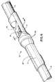
- FIG. 6 is a perspective view of the improved crimped splice of FIGS. 3-5, thereby terminating the respective stranded wire of two cables.
- FIG. 7 is a further perspective view, corresponding substantially to FIG. 6, but showing that the teachings of the present inventions are equally applicable to a terminal for the stranded wires of a single cable.
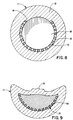
- FIG. 8 is a cross-sectional view, taken along the lines 8-8 of FIG. 5, and showing the insert sleeve circumferentially keyed to the barrel portion of the housing.
- FIG. 9 is a further cross-sectional view, taken along the lines 9-9 of FIG. 6, corresponding substantially to FIG. 8, but showing the strands of wire received within the barrel portion of the housing, and further showing the housing crimped on the wire strands, such that the wire strands tend to extrude through the perforations formed in the insert sleeve, and compressing the wire strands into a complete homogeneous mass.
- FIG. 10 is a partial longitudinal section of the housing showing a brass tapered insertion ring used in the prior art, which provides a steep (45°) angle of approach for the wire.
- FIG. 11 is a further partial longitudinal section, corresponding substantially to that of FIG. 10, but showing a plastic tapered insertion ring retained by an internal annular indentation on the barrel in accordance with the further teachings of the present invention, thereby providing a slight angle of approach for the wire of approximately 30° for an improved function.
- FIG. 12 is a perspective view of a funnel occasionally used as an accessory to facilitate the insertion of the strands of wire (or wires) into the barrel portion of the housing and, especially, inserting wires which have a natural flare due to their manufacture.
- FIG. 13 is a longitudinal sectional view, corresponding substantially to FIG. 5, but showing the funnel of FIG. 12 inserted into the barrel of the housing, thereby facilitating insertion of the multiple strands of wire (or wires) into the barrel of the housing.
- the prior art corrosion-proof sealed terminal 1 includes a hollow barrel 2 having an open end 3 for receiving an insert sleeve 4.
- the insert sleeve 4 is split and has a plurality of perforations 5.
- a tapered insertion ring 6 is received within the barrel 2, rearwardly of the insert sleeve 4, for facilitating insertion (or “lead in") of the wire strands 7 of a cable C.
- the terminal further has a flattened tongue 8 provided with an aperture 9 for mounting purposes.
- the terminal 1 is preferably made of solid copper but, if desired, may be made of aluminum and plated with copper, tin or silver.
- the cable C is provided with an insulation sheath impervious to moisture, and the insulation sheath may be covered by an abrasion-resistant sheath, if desired.
- the terminal 1 is crimped, as shown in FIG. 1, to retain the wire strands 7.
- the wire strands 7 tend to extrude through the perforations 5 in the insert sleeve 4, as described in the aforementioned '044 patent.
- a splice between the respective stranded wires of two discrete cables may be made rather than terminating the stranded wires of a single cable (as in FIGS. 1 and 2).
- a housing 10 has a barrel 11 provided with a protruding lug 12.
- the insert sleeve 13 has a notch 14 for receiving the lug 12 on the barrel 11, thereby circumferentially keying the insert sleeve 13 to the barrel 11 and preventing relative rotation therebetween.
- This structure assures that the proper "window” will be maintained at all times for the crimping process, thickening the wall section of the barrel 11, and reinforcing the housing 10 and the insert sleeve 13 at the crimp 15. Moreover, heat dissipation is improved.
- the housing 10 has an interior wall 16 separating the two barrels 11 (for splicing the respective wire strands of two discrete cables) and providing a water-tight gas-proof barrier.
- the insert sleeve 13 (only one of which is shown in FIG. 5) abuts against the interior wall 16, thereby limiting the insertion of the insert sleeve 13 into the barrel 11 of the housing 10.
- the lug 12 protrudes axially from the interior wall 16, radially inwardly of the barrel 11 of the housing 10, and in the direction of the open end 17 thereof.
- the crimping operation is conventional and involves a pair of cooperating dies (not shown). Upon initiation of the crimp, the dies will initially engage against and indent into the barrel 11 of the housing 10. This radially compresses the barrel 11 as well as the insert sleeve 13 and the wire strands 7. When the crimping operation has been completed, a button 19 is formed at the top of the barrel 11 (as shown in FIG. 6, thereby indicating that a proper termination has been completed.
- the crimping operation causes the strands 7 to rub against each other; and this breaks down any existing aluminum or copper oxide layer. The result is a "cold weld" which establishes intimate interstrand contact.
- the crimped terminal 10 may then be encapsulated in protective heat-shrinkable tubing or the like (not shown).
- a plastic tapered insertion ring 20 (FIG. 11) has been substituted for the brass tapered insertion ring 6 of the prior art (FIGS. 2 and 10).
- the plastic tapered insertion ring 20 is within the barrel 11 (rearwardly of the insert sleeve 13) and is retained therein by an internal annular indentation 21 rearwardly of the plastic tapered insertion ring 20 and substantially adjacent thereto, thereby retaining the tapered insertion ring 20.
- the tapered insertion ring 20 guides the wire strands 7 into the insert sleeve 13 within the barrel 11 of the housing 10.
- a reusable funnel 22 may be used as an accessory to the housing 10.
- the funnel 22 has a forward nipple 23 received within the barrel 11 of the housing 10.
- the insertion of the funnel 22 is limited by an annular shoulder 24 formed on the funnel 22 and abutting against the open end 17 of the barrel 11.
- the funnel 22 further has an internally tapered channel 25 (and flaring outwardly as shown in FIG. 13) for guiding the strands 7 of the wire (or wires). This prevents the individual wire strands 7 of the cable (or cables C) from becoming frayed inadvertently. After the wire strands 7 have been inserted, the funnel 22 is removed prior to the crimping operation.
- This funnel 22 is a most valued accessory when inserting wires which have a natural flare due to their manufacture. Without this funnel 22, it is nearly impossible to get all of the wire bundles into the barrel 11.
- the funnel 22 is formed by molding or the like from a resilient material, and the funnel 22 has a split 26 along at least one side thereof to allow detachment and removal from the wire 7 after complete wire insertion. If desired, the funnel 22 may be formed of two discrete mating pieces as, for example, molded hermaphroditic halves (not shown) which may be separated to allow removal from the wire 7 after crimping.
- the barrel 11 is provided with a longitudinal knurled stripe 27 for alignment purposes, as well as a pair of spaced-apart annular knurled bands 28 for depth location.
Landscapes
- Connections Effected By Soldering, Adhesion, Or Permanent Deformation (AREA)
Applications Claiming Priority (2)
| Application Number | Priority Date | Filing Date | Title |
|---|---|---|---|
| US108159 | 1987-10-13 | ||
| US10815993A | 1993-08-17 | 1993-08-17 |
Publications (2)
| Publication Number | Publication Date |
|---|---|
| EP0639869A2 true EP0639869A2 (fr) | 1995-02-22 |
| EP0639869A3 EP0639869A3 (fr) | 1996-07-17 |
Family
ID=22320634
Family Applications (1)
| Application Number | Title | Priority Date | Filing Date |
|---|---|---|---|
| EP94306005A Ceased EP0639869A3 (fr) | 1993-08-17 | 1994-08-15 | Borne ou ramificateur serti, étanche, et anticorrosif. |
Country Status (3)
| Country | Link |
|---|---|
| EP (1) | EP0639869A3 (fr) |
| JP (1) | JP3392229B2 (fr) |
| KR (1) | KR950007189A (fr) |
Cited By (4)
| Publication number | Priority date | Publication date | Assignee | Title |
|---|---|---|---|---|
| US5749756A (en) * | 1995-10-27 | 1998-05-12 | The Whitaker Corporation | Sealed corrosion-proof crimped terminal of splice |
| US5875547A (en) * | 1996-11-28 | 1999-03-02 | Alcatel | Cable sealing method |
| WO2009002410A2 (fr) * | 2007-06-21 | 2008-12-31 | Tyco Electronics Brasil Ltda | Terminaison bimétallique cuivre sur aluminium |
| WO2015003692A1 (fr) * | 2013-07-11 | 2015-01-15 | Harting Electric Gmbh & Co. Kg | Élément de contact électrique |
Families Citing this family (6)
| Publication number | Priority date | Publication date | Assignee | Title |
|---|---|---|---|---|
| JP2002313511A (ja) * | 2001-04-13 | 2002-10-25 | Masami Fujii | 接地電極 |
| JP2009009736A (ja) * | 2007-06-26 | 2009-01-15 | Auto Network Gijutsu Kenkyusho:Kk | アルミニウム電線への端子接続構造 |
| JP2014128135A (ja) * | 2012-12-27 | 2014-07-07 | Viscas Corp | 電力ケーブルの接続方法及び接続構造 |
| JP2016018671A (ja) * | 2014-07-08 | 2016-02-01 | 矢崎総業株式会社 | 端子金具、及び、端子金具付き電線 |
| DE102015012906A1 (de) * | 2015-02-27 | 2016-09-01 | Gentherm Gmbh | Hülse, Kontaktier-Einrichtung und Verfahren zum Schweißen von dünnen strangförmigen Leitern mittels Ultraschall |
| JP6628245B2 (ja) * | 2016-03-14 | 2020-01-08 | 昭和電線ケーブルシステム株式会社 | アルミニウム導体ケーブルの端末接続部 |
Citations (5)
| Publication number | Priority date | Publication date | Assignee | Title |
|---|---|---|---|---|
| US2316267A (en) * | 1942-03-23 | 1943-04-13 | Int Standard Electric Corp | Sleeve connector |
| US2958723A (en) * | 1957-10-02 | 1960-11-01 | Thomas & Betts Corp | Electrical connector and sealing means therefor |
| US3955044A (en) * | 1970-12-03 | 1976-05-04 | Amp Incorporated | Corrosion proof terminal for aluminum wire |
| EP0297493A2 (fr) * | 1987-06-30 | 1989-01-04 | Drilltec Patents & Technologies Company, Inc. | Dispositif de protection des extremités de tuyaux |
| EP0521190A1 (fr) * | 1991-06-29 | 1993-01-07 | Taller GmbH | Pont à fiches pour une fiche à contact de protection d'un appareil électrique |
-
1994
- 1994-08-05 JP JP20462394A patent/JP3392229B2/ja not_active Expired - Fee Related
- 1994-08-15 EP EP94306005A patent/EP0639869A3/fr not_active Ceased
- 1994-08-16 KR KR1019940020090A patent/KR950007189A/ko not_active Application Discontinuation
Patent Citations (5)
| Publication number | Priority date | Publication date | Assignee | Title |
|---|---|---|---|---|
| US2316267A (en) * | 1942-03-23 | 1943-04-13 | Int Standard Electric Corp | Sleeve connector |
| US2958723A (en) * | 1957-10-02 | 1960-11-01 | Thomas & Betts Corp | Electrical connector and sealing means therefor |
| US3955044A (en) * | 1970-12-03 | 1976-05-04 | Amp Incorporated | Corrosion proof terminal for aluminum wire |
| EP0297493A2 (fr) * | 1987-06-30 | 1989-01-04 | Drilltec Patents & Technologies Company, Inc. | Dispositif de protection des extremités de tuyaux |
| EP0521190A1 (fr) * | 1991-06-29 | 1993-01-07 | Taller GmbH | Pont à fiches pour une fiche à contact de protection d'un appareil électrique |
Cited By (6)
| Publication number | Priority date | Publication date | Assignee | Title |
|---|---|---|---|---|
| US5749756A (en) * | 1995-10-27 | 1998-05-12 | The Whitaker Corporation | Sealed corrosion-proof crimped terminal of splice |
| US5875547A (en) * | 1996-11-28 | 1999-03-02 | Alcatel | Cable sealing method |
| WO2009002410A2 (fr) * | 2007-06-21 | 2008-12-31 | Tyco Electronics Brasil Ltda | Terminaison bimétallique cuivre sur aluminium |
| WO2009002410A3 (fr) * | 2007-06-21 | 2009-02-12 | Tyco Electronics Brasil Ltda | Terminaison bimétallique cuivre sur aluminium |
| WO2015003692A1 (fr) * | 2013-07-11 | 2015-01-15 | Harting Electric Gmbh & Co. Kg | Élément de contact électrique |
| US9502786B2 (en) | 2013-07-11 | 2016-11-22 | Harting Electric Gmbh & Co. Kg | Electrical contact element |
Also Published As
| Publication number | Publication date |
|---|---|
| JP3392229B2 (ja) | 2003-03-31 |
| EP0639869A3 (fr) | 1996-07-17 |
| KR950007189A (ko) | 1995-03-21 |
| JPH07153502A (ja) | 1995-06-16 |
Similar Documents
| Publication | Publication Date | Title |
|---|---|---|
| US5749756A (en) | Sealed corrosion-proof crimped terminal of splice | |
| US5393244A (en) | Twist-on coaxial cable end connector with internal post | |
| US5195906A (en) | Coaxial cable end connector | |
| US3955044A (en) | Corrosion proof terminal for aluminum wire | |
| US3384704A (en) | Connector for composite cables | |
| US7160156B2 (en) | Crimpable wire connector assembly | |
| EP0597579A2 (fr) | Connecteur d'interconnexion pour câbles coaxiaux | |
| US5660565A (en) | Coaxial cable connector | |
| US4415223A (en) | Interlocking crimp sleeve and method of securing to connector | |
| US2904619A (en) | Shielded wire connectors | |
| US4206958A (en) | Electrical conductor having an integral electrical contact | |
| JP4097589B2 (ja) | ケーブル用コネクタ | |
| US20090215306A1 (en) | Electrical connector with compression gores | |
| US4342496A (en) | Contact assembly incorporating retaining means | |
| US3297979A (en) | Crimpable coaxial connector | |
| EP0639869A2 (fr) | Borne ou ramificateur serti, étanche, et anticorrosif | |
| US3331917A (en) | Coaxial and shielded in-line termination | |
| EP0536849B1 (fr) | Dispositif de contact pour câble avec un ou plusieurs conducteurs internes | |
| US3356987A (en) | Insulation support and wire guide for an electrical connector | |
| US5085594A (en) | Solder-free plug-cable connection system | |
| US3594713A (en) | Electrical connector | |
| EP1397846B1 (fr) | Connecteur electrique non serti de type cote a cote | |
| US5522739A (en) | Insulated terminal with integral dual flared barrel | |
| US20240178584A1 (en) | Manufacturing method for terminal-equipped electric wire, and terminal-equipped electric wire | |
| US4392703A (en) | Electrical conductor having an integral electrical contact |
Legal Events
| Date | Code | Title | Description |
|---|---|---|---|
| PUAI | Public reference made under article 153(3) epc to a published international application that has entered the european phase |
Free format text: ORIGINAL CODE: 0009012 |
|
| AK | Designated contracting states |
Kind code of ref document: A2 Designated state(s): DE ES FR GB IT NL SE |
|
| PUAL | Search report despatched |
Free format text: ORIGINAL CODE: 0009013 |
|
| AK | Designated contracting states |
Kind code of ref document: A3 Designated state(s): DE ES FR GB IT NL SE |
|
| 17P | Request for examination filed |
Effective date: 19970109 |
|
| GRAG | Despatch of communication of intention to grant |
Free format text: ORIGINAL CODE: EPIDOS AGRA |
|
| 17Q | First examination report despatched |
Effective date: 19990407 |
|
| STAA | Information on the status of an ep patent application or granted ep patent |
Free format text: STATUS: THE APPLICATION HAS BEEN REFUSED |
|
| 18R | Application refused |
Effective date: 19991127 |