EP0637814B1 - Méthode et appareil pour effectuer le mappage de texture sur des surfaces complexes - Google Patents
Méthode et appareil pour effectuer le mappage de texture sur des surfaces complexes Download PDFInfo
- Publication number
- EP0637814B1 EP0637814B1 EP94305461A EP94305461A EP0637814B1 EP 0637814 B1 EP0637814 B1 EP 0637814B1 EP 94305461 A EP94305461 A EP 94305461A EP 94305461 A EP94305461 A EP 94305461A EP 0637814 B1 EP0637814 B1 EP 0637814B1
- Authority
- EP
- European Patent Office
- Prior art keywords
- space
- texture
- mapping
- values
- vertices
- Prior art date
- Legal status (The legal status is an assumption and is not a legal conclusion. Google has not performed a legal analysis and makes no representation as to the accuracy of the status listed.)
- Expired - Lifetime
Links
- 238000000034 method Methods 0.000 title claims description 107
- 238000013507 mapping Methods 0.000 title claims description 83
- 239000003086 colorant Substances 0.000 claims description 31
- 230000009466 transformation Effects 0.000 claims description 18
- 230000006870 function Effects 0.000 claims description 14
- 238000009877 rendering Methods 0.000 claims description 9
- 238000012545 processing Methods 0.000 claims description 5
- 238000012935 Averaging Methods 0.000 claims description 4
- 230000006399 behavior Effects 0.000 claims description 4
- 230000001131 transforming effect Effects 0.000 claims 4
- 230000008569 process Effects 0.000 description 62
- 238000000844 transformation Methods 0.000 description 5
- 238000010586 diagram Methods 0.000 description 4
- 230000008901 benefit Effects 0.000 description 3
- OAICVXFJPJFONN-UHFFFAOYSA-N Phosphorus Chemical compound [P] OAICVXFJPJFONN-UHFFFAOYSA-N 0.000 description 2
- 238000013459 approach Methods 0.000 description 2
- 230000001419 dependent effect Effects 0.000 description 2
- 238000013461 design Methods 0.000 description 2
- 230000000694 effects Effects 0.000 description 2
- 230000002452 interceptive effect Effects 0.000 description 2
- 238000012986 modification Methods 0.000 description 2
- 230000004048 modification Effects 0.000 description 2
- 230000003252 repetitive effect Effects 0.000 description 2
- 230000003044 adaptive effect Effects 0.000 description 1
- 238000005452 bending Methods 0.000 description 1
- 230000015572 biosynthetic process Effects 0.000 description 1
- 238000001914 filtration Methods 0.000 description 1
- 230000002093 peripheral effect Effects 0.000 description 1
- 238000003786 synthesis reaction Methods 0.000 description 1
- 230000000007 visual effect Effects 0.000 description 1
Images
Classifications
-
- G—PHYSICS
- G06—COMPUTING; CALCULATING OR COUNTING
- G06T—IMAGE DATA PROCESSING OR GENERATION, IN GENERAL
- G06T15/00—3D [Three Dimensional] image rendering
- G06T15/04—Texture mapping
Definitions
- the present invention relates to a system and method for rendering textured objects. Particularly, the present invention relates to a system and method for rendering textured NURBS surfaces.
- texture mapping a map of the texture is generated in a texture coordinate (TC) space.
- the object to which the texture is to be applied is realized in modeling coordinate (MC) space.
- a binding processes is then performed to define the correspondence of the texture coordinates to the object coordinates.
- the binding process binds the coordinates of the texture map in TC space (e.g., u,v coordinates) to predetermined coordinates of the object in MC space (e.g., x,y,z,w coordinates).
- TC space e.g., u,v coordinates
- predetermined coordinates of the object in MC space e.g., x,y,z,w coordinates.
- a subset of all possible points of the object is typically used, such as the vertices of the object.
- the object is mapped to device coordinate space (DC).
- DC device coordinate space
- an interpolation process using the subset of all possible points binded, is performed to determine the elements of the texture map to be applied to each coordinate of the object in DC space.
- a color composition process is subsequently performed to incorporate the colors of the texture map onto the object in the display coordinate space. This object with the colors of the texture is then displayed on the display device.
- the binding process is performed for each object and texture combination and the application of different texture maps to the same object requires separate binding processes.
- objects defined in parameter coordinate (PC) space such as non-uniform rational B-spline surfaces (NURBS)
- NURBS non-uniform rational B-spline surfaces
- texture mapping can be found in an article entitled “A high-quality filtering using forward texture mapping” by D. Ghazanfarpour and B. Peroche, Computers & Graphics, Vol. 15(2), 1991, p.569-577, and also in an article entitled “Hierarchical texture synthesis on 3-D surfaces” by Chakib Bennis and André Gagalowicz, Eurographics, '89, W. Hansmann, F.R.A. Hopgood and W. Strasser (ed), p.257-269.
- MC modeling coordinate
- WC world coordinate
- PC parameter coordinate
- a mapping between the PC space and texture coordinate (TC) space is generated.
- This mapping referred to herein as the ⁇ mapping, correlates the (s 1 ...s n ) coordinates of the PC space to the (u 1 ...u n ) coordinates of the TC space.
- the object is mapped from the MC space to the display coordinate (DC) and the ⁇ mapping is then used to map the texture map onto the selected points of the object, such as the vertices of the object.
- object parameter interpolation is then performed to render the pixels of the object, including the location, colors and intensity of the pixel, in the DC space.
- a color composition process is executed to interpolate the colors of the mapped texture to render a texture color for each pixel and a composition process is performed to combine the texture colors with the pixels of the object.
- Other processes and sequences for performing object parameter interpolation, texture mapping, texture interpolation and texture/object composition can also be used.
- the granularity of the texture applied to the object can be controlled using such techniques as mipmap criteria, texture quality or, in the case of NURBS, NURBS approximation criteria.
- the method and apparatus of the present invention performs the complex operation of applying texture to objects, including complex objects such as NURBS, in a manner that minimizes computation of mapping functions between textures and objects while enabling the capability to control the quality or granularity of the texture rendered including the capability to provide such graphical aspects as warping.
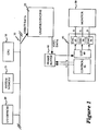
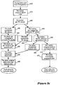
- the system of the present invention is conceptually illustrated by the block diagram of Fig. 1 .
- a CPU 10, system memory 15, Input/Output (I/O) devices 20 and a graphics subsystem 25 are coupled via a system bus 30.
- the CPU 10 functions as the central or host processor and typically executes application programs that generate the objects and apply texture maps to the objects which are displayed in accordance with the present invention.
- the CPU 10 functions as a powerful general purpose processor and utilizes the available resources such as the system memory 15, I/O devices 20 and other peripherals devices (not shown) to execute complex programs and processes.
- the CPU 10 may be configured into a system or workstation such as those manufactured by Sun Microsystems, Inc, Mountain View, California.
- the graphics subsystem is preferably configured to execute graphic specific, often repetitive, processes to off-load the processing overhead from the CPU 10.
- the system 25 includes a floating point processor, memory and VLSI, and is configured to execute simple, but costly and highly repetitive computations required as part of the process for rendering objects with texture.
- the computations can be performed by special, dedicated hardware, such as special VLSI devices for the rendering of triangles representative of the object, in order to further increase the speed of performing the processes.
- a floating point processor may tessellate the object to triangles and apply the texture to the triangles.
- the VLSI component then translates the triangles into pixel data for storage in the frame buffer 40.
- the pixel data is stored in the frame buffer 40 in a sequence readily identified with the x-y coordinate space of the display device 50.
- the display controller 45 generates the display of the object defined by the pixel data located in the frame buffer.
- the display controller 45 through its controller 55 cycles through the frame buffer, one scan line at a time in accordance with the raster scan rate, for example, 60 times a second.
- Memory addresses are generated by the controller 55 to access the pixel data.
- the pixel data is read from the frame buffer in sequence and input to the display controller color look-up table (LUT) 60.
- the LUT 60 contains the digital control signals used to control the intensity and color of the output, for example beams of electrons, on the display device 50.
- the signals output by the LUT 60 are input to digital to analog converters (DACs) 65, 70 and 75 which generate the analog signals to control the energizing or generation of the location an intensity respectively of the red, green and blue components of the pixel to be displayed.
- the display device may be a raster scan device such as a cathode ray tube (CRT).
- CRT cathode ray tube
- the display device will be a CRT; however, it is obvious to one skilled in the art that other display devices may be utilized in accordance with the system of the present invention.
- the analog control signals control the number of electrons in the beam.
- the number of electrons in the beam is determinative of the intensity displayed. By controlling the red, green and blue beams for each pixel in this manner, varying colors and intensities can be produced on the display device.
- the beam(s) of electrons are directed towards a phosphor coated screen by a high positive voltage applied.
- the beams are directed toward a particular location (reflective of the x-y coordinate location of the pixel data) by a magnetic field produced by deflection coils.
- the phosphor emits visible light, the intensity emitted dependent upon the number of electrons which hit the screen.
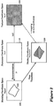
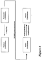
- the process of the present invention is described generally with reference to Fig. 2.
- the object is described in MC space 105 or, alternately, world coordinate (WC) space.
- the texture map is defined in TC space 120.
- the object is subsequently rendered and displayed in the DC space 130.
- a parameterization process "P" is used to bind the object 110 to the PC space 115. This process is performed once for an object and is view independent and texture independent.
- a mapping is then performed between the TC space 120 and PC space 115. This mapping is referred to herein as the ⁇ mapping.
- the ⁇ mapping is subsequently used to apply the texture map to the object 110 in the display coordinate space 130.
- the ⁇ mapping is utilized to bring the corresponding texture map values to the DC space where it is applied to predetermined points of the object, such as the vertices of the object.
- the texture values are interpolated to apply a texture value to each pixel of the object.
- a color composition process is then performed to combine the texture values with the colors of the object to generate a pixel image which is stored in the frame buffer and subsequently displayed.
- the process of the present invention introduces a new degree of freedom in the modification of texture images as a result of the ability to control the process of texture mapping independently of the primitives' geometry.
- this process provides an implementation for a flexible, adaptive strategy for texture mapping wherein all types of primitives are supported.
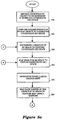
- varying levels of quality of the actual textures utilized can be controlled. The process is described in further detail with respect to Figs. 3a, 3b and 3c .
- the system first receives a definition of the object to be rendered in the modeling coordinates, step 200 (it should be noted that the MC space is also referred to as the object coordinate space).
- a parameterization process is performed to construct a PC space associated with the object.
- An object typically a surface, is defined in three dimensional space (e.g., MC space) and therfore coordinates (x,y,z) or alternately, (x,y,z,w) are used.
- a parameter space is typically a two dimensional space (s,t), defined in such a manner that each point on the object in MC space can be obtained by a mathematical or predefined function of s and t.
- This function maps the parameter space into MC space.
- an independent representation of the object is achieved in PC space.
- the parameterization process can be thought of as binding process where, for example, with respect to polygon primitives, predetermined points (for example, the vertices of the object) on the polygon primitive are assigned or binded to values in the PC space.
- binding process where, for example, with respect to polygon primitives, predetermined points (for example, the vertices of the object) on the polygon primitive are assigned or binded to values in the PC space.
- this step is not considered an additional step because the complex surfaces are defined in parameter space.
- Parameterization is typically a complex process as it involves bending two dimensional parameter values to a three dimensional object. Therefore, an advantage is achieved as the parameterization step is only performed once for any given object.
- the ⁇ mapping of the PC space to the TC space is generated.
- This mapping is subsequently used to identify the texture coordinates corresponding to points of the object transformed into the DC space.
- This mapping also maintains the texture and parameter coordinates as separate parameters. Therefore, the parameter space can be regarded as a property of the primitive and the texture as a separate entity which is subsequently applied to the object.
- the displayed texture image can be easily controlled and modified without modifying the object or the texture map itself.
- ⁇ mapping is a lot simpler process than parameterization because same-dimensional (e.g., 2 dimensional) spaces are involved, and therefore lends itself to re-execution for different texturing effects.
- very useful quality measures and dynamic texturing for splines can be implemented.
- parameter and texture space can be configured to coincide.
- This embodiment corresponds to traditional texture mapping in which a one-to-one or identity map is established.
- supporting non-identity maps is desirable to enable arbitrary warping effects to be performed on a given texture map to modify the displayed texture.
- This function can be defined to provide a variety of mappings including an identity function. It should be realized that the image of ⁇ mapping does not have to coincide necessarily with the entire texture space. In that instance, portions of the texture map may not be utilized to generate the texture on the object
- the only restriction on P is that it should contain all four corners, (smin,tmin), (smin,tmax), (smax,tmin), (smax,tmax), of the PC space.
- the interpolation process utilized can be a piece-wise linear interpolation or a spline of a higher order.
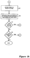
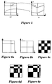
- Fig. 5 shows a rectangular grid in PC space and corresponding interpolation values in TC space.
- the ⁇ mapping can be performed to map a texture coordinate of the texture map on each pixel of the object in the display space, this is a computationally intensive operation, especially if the mapping is spline-based.
- the ⁇ mapping e.g., the corresponding texture coordinates
- the subset of points can be a set of predetermined points, such as the vertices of the object.
- the mapping identifies only the corresponding texture coordinates for the subset of points, the texture coordinates for pixels between vertices are then determined by interpolating between the subset of points. That is, instead of applying the ⁇ mapping at every pixel in order to determine the texture coordinates, texture coordinates for a subset of pixels can be determined and the texture values for the remaining pixels are generated by interpolation.
- linear interpolation One interpolation method that can be utilized is linear interpolation.
- a triangulation of the set P is performed using available techniques such as the Voronoi diagrams. See (Franco Preparata and Michael Shamos, "Computational Geometry: An Introduction", Springer-Verlag 1988, pp. 198-216).
- the texture coordinates of the image of this point is calculated using the barycentric coordinates in the TC space.
- This method is very general and works for arbitrary sets of P.
- spline interpolation on triangles can be used instead of linear interpolation.
- triangular spline interpolation see, for example, G Farin, Curves and Surfaces for Geometric Design , (Academic Press 1991), pp. 235-254.
- bilinear interpolation on rectangles can be used. This approach assumes that the set P forms a regular grid. A bilinear interpolation is then used to determine the mapping for the intermediate points. Generally, the process of finding a rectangle in PC space containing the given point is simpler than finding the corresponding triangle.
- P may be defined to form a regular grid. If P does not form a regular grid, the smallest grid containing P is constructed. This can be accomplished by drawing vertical and horizontal lines through each point in the set P. The intersecting points of these lines then form a regular grid P' containing P. The interpolation values for the points in P'-P can again be estimated using linear interpolation.
- Figs. 6a through 6e Exemplary results of bilinear and smooth interpolation on rectangles are shown on Figs. 6a through 6e .
- Figs. 6a and 6b show interpolation grids in PC space and TC space respectively.
- Fig. 6c shows a checkered board texture map.
- Fig. 6d shows a resulting image after applying bilinear interpolation mapping between PC and TC.
- Fig. 6e shows the same image after applying smooth interpolation mapping.
- the tessellation granularity is determined. This is an optional step which is particularly useful for the dynamic tessellation of textured NURBS surfaces. It is preferred that at this point in the process the NURBS object is tessellated into facets. Although, the discussion below is in the context of NURBS, it is apparent to one skilled in the art that the techniques are readily applicable to other types of surfaces as well as other types of primitive objects. The concept of dynamic tessellation of NURBS curves and surfaces can therefore be expanded to include textured NURBS surfaces.
- the tessellation threshold criteria can be specified in DC space, MC space, PC space or TC space in order to achieve the tessellation granularity desired.
- Abi-Ezzi, et al (see, for example, Abi-Ezzi, Shirman, "The Tessellation of Curved Surfaces Under Highly Varying Transformations", Proceedings Eurographics '91, 1991, pp. 385-397) describes the concept of dynamic tessellation of NURBS curves and surfaces.
- a NURBS surface described by control points is displayed by breaking or tessellating the surface into planar facets (such as triangles) defined by vertices and rendering the planar facets.
- the granularity of the tessellation is controlled by the application specified approximation criteria. For example, the application may require that the maximum size of a facet in DC or WC can not exceed a specified tolerance. Therefore, when a viewing or modeling transformation changes, the tessellation is dynamically adjusted to honor the approximation criteria.
- NURBS are tessellated in WC or LC space Abi-Ezzi, et al (see, for example, Abi-Ezzi, Shirman, "The Tessellation of Curved Surfaces Under Highly Varying Transformations", Proceedings Eurographics '91, 1991, pp. 385-397).
- tessellation is assumed to occur in MC or WC space.
- an estimate of how a tolerance specified in DC is mapped to MC is determined.
- this is determined by generation of a closed form expression for the minimum and maximum scale factors of a perspective transformation in a bounded region.
- Fig. 4 visually illustrates various coordinate spaces and mappings between them.
- the bounds on the PC to TC i.e., the ⁇ mapping
- the NURBS is tessellated at specified regular intervals in PC space (i.e., constant parametric approximation criterion).
- thresholds can be specified in TC, PC, MC, or DC space and the surface can be dynamically tessellated to meet the thresholds.
- n s and n t are the required number of steps or segments in the s and t direction, respectively
- d s,mc and d t,mc represent the thresholds of the NURBS in MC space
- ⁇ S's ⁇ and ⁇ S't ⁇ are the maximum derivative bounds of the surface patch in corresponding directions (it is assumed here that the patch is parameterized from 0 to 1) in MC space.
- the sizes d s,dc , d t,dc are mapped to MC space using the scaling behavior of a viewing transformation and the norm of the modeling transformation.
- threshold in MC space see for example, Abi-Ezzi, Shirman, "Scaling Behavior of Viewing Transformations", Computer Graphics and Applications, May 1993.
- the maximum size d is specified in TC space (i.e., texels)
- the minimum size in PC is estimated using the ⁇ mapping: where ⁇ ' / s ⁇ and ⁇ ' / t ⁇ are the maximum derivative bounds of the ⁇ mapping in s,t.
- the number of segments is then determined to be the inverses of d s,pc and d t,pc :
- threshold specified in DC space is view dependent while the threshold specified in TC space is not.
- the function g is typically an averaging function. For example, could be defined as: min(max(n N n T ),thresh)
- step size determined according thresholds specified in TC and MC or DC can be averaged to generate a uniform step size for tessellation.
- the thresholds can also be used to determine the appropriate mip-map level. Once the number of steps n s , n t have been determined according to one of the above formulas, the thresholds in TC space can be determined as follows:
- the mip-map level can then be determined by, for example: where l represents the mip-map level, f(d s,tc , d t,tc ) represents some function of the thresholds, such as the product of the thresholds or the maximum of the product squared, and it is assumed that the TC space ranges from 0 to 1 in both u and v.
- the object located in MC space is mapped to the display coordinate (DC) space.
- This step is accomplished using a variety of known techniques.
- the object in MC space is transformed to the world coordinate (WC) system by a modeling transformation.
- the World Coordinate system is the coordinate system in which the different portions of a graphic object to be rendered are assembled.
- the graphic object in the WC system is transformed to the DC system which corresponds to the screen space of the display.
- the object can be transformed to lighting coordinate (LC) space through a rigid transformation and subsequently to the DC space through a sparse transformation (see, Abi-Ezzi, Wozny, "Factoring a Homogenous Transformation for a More Efficient Graphics Pipeline", Computer Graphics, Vol. 15, No. 2, pp. 249-258, 1991).
- LC lighting coordinate
- step 250 can be achieved a variety of ways. The process is explained with reference to Fig. 3c .
- step 415 the colors at the vertices are determined.
- the corresponding PC coordinate values at the vertices are retrieved, step 420.
- interpolation is performed on the vertices of the object to generate the individual pixels representative of the object (step 425).
- Well known techniques are used to generate the pixel image from predetermined parameters of the object (such as the vertices of the object) such as line scan algorithms and the like.
- NURBS for complex objects like NURBS, other known techniques are utilized, such as triangulation of the object surfaces and subsequently rendering the triangles generated using known scan line algorithms.
- the ⁇ mapping is used to determine the corresponding TC coordinates for each pixel (step 430).
- the texture colors are then determined a variety of known techniques can be used, such as a direct lookup of texture values.
- techniques such as mip-mapping and summed area tables can be used to perform the interpolation. See, for example, Williams, "Pyramidal Parametrics", Computer Graphics, Vol. 17, No. 3, July 1983 and “Crow, Summed Area Tables for Texture Mapping", Computer Graphics, Vol. 18, No. 3, pp. 207-211, July 1984.
- interpolation of the object colors at the vertices is performed to determine the object colors at each pixel.
- a composition process is then performed, step 445 to compose or combine the object color and texture color to determine the final pixel color for the textured object.
- the texture color can simply replace the object color and therefore the pixel color will be the texture color.
- the pixel color can be the a combination of both the object color and texture color, such as simple averaging, weighted sum or averaging or the like.
- Solaris (R) XGLTM 3.0.1 Programmer's Guide, SunSoft (1993, Sun Microsystems, Inc) pp. 387-389.
- the following process may be used. This process is preferred when the granularity of tessellation is determined using thresholds specified in TC space.
- the TC coordinate values corresponding to the vertices of the object are first determined using the ⁇ mapping, step 450. Once the TC coordinate values are determined, interpolation processes can be performed at different levels of information in order to determine the pixel colors of the textured object. In this process, represented by steps 455, 435, 440, 445, the TC coordinate values are interpolated to determine the corresponding TC values at the vertices of the object.
- the texture colors are then extracted (step 435), the object colors interpolated (step 440) and the object color and texture color at each pixel are composed to generate the pixel color for the textured object (step 445).
- step 460 the texture color at each vertex is determined, step 460.
- interpolation can be performed on the texture color values to generate texture color values for each pixel of the object (step 465) or a composition process can be performed at the vertices to combine the object color at each vertex with the corresponding texture color (step 470).
- the texture color interpolation process is performed (step 465), the object colors at the object vertices are then interpolated to generate a color value at each pixel of the object (step 440) and at each pixel, a composition process is performed to generate the colors of texture object (step 445). If the composition process is first performed (step 470), an interpolation of the composed colors at the vertices are interpolated, step 475, to generate the colors of the textured object.
- interpolating the texture color e.g., steps 415, 420, 450, 460, 465, 440, 445
- interpolation of the composed vertex colors e.g., steps 415, 420, 450, 460, 470, 475 which is the fastest process as the number of per-pixel operations is limited to the last step (step 475) in which the composed colors are interpolated.
- the resultant pixels generated with corresponding color and intensity values are stored in the frame buffer, step 290.
- the pixels are actuated on the display at the location and intensity identified by the pixel data stored in frame buffer to generate on the display the textured object.
- step 310 One readily apparent advantage to the process is that the entire process does not need to be re-executed if, for example, a new view of the object is to be rendered, step 310 . If a new view is to be rendered, the process branches to step 230 thereby eliminating the need to reperform the parameterization process (step 210) and the determination of the ⁇ mapping (step 220). Similarly, at step 320, a new texture map can be generated with respect to the same object. In this case, the ⁇ mapping at step 220 would be regenerated to accommodate a new texture map and the process of parameterization of the object, step 210, does need not be re-executed. This allows the generation of special visual effects, such as warping and the like, without affecting any texture and parameterizations performed.
- special visual effects such as warping and the like
Landscapes
- Engineering & Computer Science (AREA)
- Computer Graphics (AREA)
- Physics & Mathematics (AREA)
- General Physics & Mathematics (AREA)
- Theoretical Computer Science (AREA)
- Image Generation (AREA)
Claims (19)
- Procédé pour projeter des objets texturés dans un dispositif d'affichage graphique (50) d'un système d'ordinateur comprenant une unité centrale de traitement (CPU) (10), une mémoire et des dispositifs d'entrée/sortie (20) incluant un contrôleur d'affichage graphique (45) couplé au dispositif d'affichage graphique (50), chacun desdits objets texturés comprenant un objet (110) et une texture appliquée à l'objet (110), lesdits objets étant définis par une pluralité de sommets dans un espace (105) de coordonnées de modélisation (MC), transformé dans un espace de coordonnées du monde (WC) et reproduits sous la forme d'images dans l'espace (130) de coordonnées de dispositif (DC), chaque sommet possédant une valeur de couleur associée, ledit dispositif d'affichage graphique étant défini conformément à l'espace DC, ladite texture étant définie par une carte de texture dans l'espace (120) de coordonnées de texture (TC), ladite carte de texture identifiant les couleurs de la texture, ledit procédé comprenant les étapes consistant à :construire un espace (115) de coordonnées de paramètres (PC) associé à l'objet (110);produire une projection τ de l'espace PC (115) sur l'espace TC (120), ladite projection τ mettant en corrélation les coordonnées de l'espace PC et les coordonnées de l'espace TC;transformer les sommets de l'objet dans l'espace MC (105), dans l'espace DC (130);projeter la carte de texture sur l'objet dans l'espace DC (130) en utilisant la projection τ;composer les valeurs de couleurs de l'objet avec des valeurs de texture projetées pour produire des données de pixels de l'objet texturé;mémoriser chacune desdites données de pixels dans un tampon d'images (140), chaque donnée de pixel étant mémorisée en un emplacement dans le tampon d'images, qui correspond à l'emplacement du pixel dans l'espace DC (130); etledit contrôleur d'affichage graphique (45) lisant les données de pixels mémorisées dans le tampon d'images (40) et produisant des signaux de commande pour activer les pixels à l'emplacement et avec la couleur indiqués par les données de pixels;les objets texturés étant produits pour un affichage.
- Procédé selon la revendication 1, selon lequel l'étape de construction dans l'espace (115) de coordonnées de paramètres (PC) associé à l'objet (110) comprend l'étape d'affectation des sommets de l'objet (110) dans l'espace MC (105) à des valeurs dans l'espace PC (115).
- Procédé selon la revendication 1, selon lequel l'étape de production d'une projection τ comprend l'étape de définition par spécification directe, lors de laquelle les coordonnées (u,v) de l'espace TC (120) sont spécifiées avec une coordonnée correspondante (s,t) de l'espace PC (115), de telle sorte que l'on a
- Procédé selon la revendication 1, selon lequel l'étape de production d'une projection τ comprend les étapes consistant à :sélectionner un ensemble de points dans l'espace PC (115),déterminer un ensemble de valeurs d'interpolation de l'espace TC (120),interpoler les coordonnées (u,v) devant être interpolées pour produire la projection τ.
- Procédé selon la revendication 4, selon lequel l'étape d'interpolation comprend une interpolation linéaire.
- Procédé selon la revendication 4, selon lequel l'étape d'interpolation comprend une interpolation par courbe spline.
- Procédé selon la revendication 1, comprenant en outre l'étape consistant à déterminer la granularité de la représentation mosaïque de la texture appliquée à l'objet.
- Procédé selon la revendication 7, selon lequel l'objet comprend une surface NURBS, le critère de la représentation mosaïque pour la texture, et la surface NURBS spécifiée dans l'espace MC (105) et le nombre de pas dans l'espace PC (115) pour former la représentation mosaïque de la texture et de l'objet pour obtenir les sommets associés à l'objet représenté sous forme mosaïque sont déterminés conformément à ce qui suit :ns et nt représentant le nombre requis d'étapes ou de segments dans les directions respectives s et t, ds,mc et dt,mc représentant des surfaces NURBS dans l'espace MC, et ||S's|| et ||S't|| étant les limites maximales de dérivée de l'élément de surface dans les directions s et t dans l'espace MC (105).

- Procédé selon la revendication 7, selon lequel l'objet comprend une surface NURBS, le critère de seuil de représentation mosaïque est spécifié dans l'espace TC (120) et le nombre d'étapes dans l'espace PC (115) pour former la représentation mosaïque de la structure et de l'objet pour obtenir les sommets associés à l'objet représenté au moyen d'une représentation mosaïque est déterminé conformément à ce qui suit :ds,tc et dt,tc représentant des seuils dans l'espace (120), et ||τ's|| et ||τ't|| sont les limites de dérivée maximales de la projection dans s, t.

- Procédé selon la revendication 7, dans lequel l'objet comprend une surface NURBS, le critère de seuil de représentation mosaïque est spécifié dans l'espace DC (130) de même que le nombre d'étapes dans l'espace DC (120) pour la représentation mosaïque de l'objet, et l'étape de détermination de la granulosité de la représentation mosaïque comprend les étapes consistant à :faire une projection des critères de seuil ds,dc et dt,dc sur l'espace MC (105) pour obtenir ds,mc et dt,mc en utilisant le comportement de cadrage d'échelle de transformation d'observation pour l'objet et la norme d'une transformation de modélisation; etdétermination du nombre d'étapes ns, nt conformément à ce qui suit :||S's|| et ||S't|| étant les limites de dérivée maximales de l'élément de surface dans les dimensions s et t dans l'espace MC.

- Procédé selon la revendication 7, selon lequel l'objet comprend une surface NURBS, le critère de seuil de représentation mosaïque est spécifié dans l'espace MC (1050) ou dans l'espace DC (120) et dans l'espace TC (120) de même que le nombre d'étapes dans l'espace PC (115) pour fournir la représentation mosaïque de l'objet, et l'étape de détermination de la granularité de représentation mosaïque comprend les étapes consistant à :déterminer le nombre d'étapes à partir du critère de seuil spécifié dans l'espace MC/DC;déterminer le nombre d'étapes à partir du critère de seuil spécifié dans l'espace TC;produire une seule taille à partir des deux critères de seuil conformément à ce qui suit :
- Procédé selon la revendication 7, ledit procédé comprenant en outre l'étape consistant, une fois que la granularité de représentation mosaïque ns, nt est déterminée, à déterminer un niveau de carte mip-map de la texture à partir des critères de seuil correspondants dans l'espace TC (120), conformément à ce qui suit :||τ's|| et ||τ't|| étant les limites de dérivée maximales de la projection τ dans s,t.

- Procédé selon la revendication 12, selon lequel l'étape de détermination du niveau de carte mip est exécutée conformément à :l représentant le niveau de carte mip, f(ds,tc,dt,tc), représentant une fonction des valeurs de seuil.

- Procédé selon la revendication 1, selon lequel l'étape de transformation des sommets de l'objet dans l'espace MC (105), dans l'espace DC (130) comprend l'étape de transformation de l'objet par l'intermédiaire d'une transformation de modélisation.
- Procédé selon la revendication 1, dans lequel les étapes de projection de la carte de texture sur l'objet dans l'espace DC (105) en utilisant la projection τ et en composant les valeurs de couleurs de l'objet avec les valeurs de texture projetées pour produire des données de pixels de l'objet texturé comprennent les étapes consistant à :déterminer les valeurs PC des sommets;interpoler les valeurs PC des sommets pour produire des valeurs PC des pixels constituant l'objet;pour chaque pixel, calculer les valeurs TC correspondantes de la carte de texture en utilisant la projection;pour chaque pixel, déterminer la couleur de texture pour les valeurs TC correspondantes;interpoler les couleurs de l'objet au niveau des sommets pour déterminer les couleurs de l'objet au niveau de chaque pixel; etcomposer la couleur de l'objet et la couleur de texture au niveau de chaque pixel pour produire les données de pixels de l'objet.
- Procédé selon la revendication 1, selon lequel les étapes de projection de la carte de texture sur l'objet dans l'espace DC (130) en utilisant la projection τ et en composant les valeurs de couleur de l'objet avec les valeurs de texture projetées pour produire des données de pixel de l'objet texturé comprend les étapes consistant à :déterminer les valeurs PC des sommets;en utilisant la projection τ, calculer les valeurs TC pour les sommets;interpoler les valeurs TC au niveau des sommets pour déterminer une valeur TC pour chaque pixel de l'objet;pour chaque pixel, déterminer la couleur de texture pour les valeurs TC correspondantes;interpoler les couleurs d'objets au niveau des sommets pour déterminer les couleurs de l'objet au niveau de chaque pixel; etcomposer la couleur de l'objet et la couleur de texture au niveau de chaque pixel pour produire les données de pixels de l'objet.
- Procédé selon la revendication 1, selon lequel les étapes de la projection de la carte de texture sur l'objet dans l'espace DC (130) en utilisant la projection τ et en composant les valeurs de couleurs de l'objet avec les valeurs de texture projetées pour produire les données de pixels de l'objet texturé, comprennent les étapes consistant à :déterminer les valeurs PC des sommets;en utilisant la projection τ, calculer les valeurs TC au niveau des sommets;déterminer la couleur de texture à partir des valeurs TC au niveau des sommets;interpoler les couleurs de texture au niveau des sommets pour déterminer une couleur de texture pour chaque pixel de l'objet;interpoler les couleurs de l'objet au niveau des sommets pour déterminer les couleurs de l'objet au niveau de chaque pixel; etcomposer la couleur de l'objet et la couleur de la texture au niveau de chaque pixel pour produire les données de pixels de l'objet.
- Procédé selon la revendication 1, selon lequel les étapes de projection de la carte de texture sur l'objet dans l'espace DC (130) en utilisant la projection τ et de composition des valeurs de couleurs de l'objet avec les valeurs de texture projetées de manière à produire des données de pixel de l'objet texturé comprennent les étapes consistant à :déterminer les valeurs PC des sommets;en utilisant la projection τ, calculer les valeurs TC au niveau des sommets;déterminer la couleur de texture à partir des valeurs TC au niveau des sommets;composer la couleur de l'objet et la couleur de texture au niveau de chaque sommet;interpoler les couleurs composées au niveau des sommets pour déterminer une couleur pour chaque pixel de l'objet pour produire les données de pixels de l'objet.
- Dispositif pour la reproduction d'objets texturés sur un dispositif d'affichage graphique (50), destiné à être utilisé dans le système d'ordinateur comprenant une unité centrale de traitement (CPU) (10), une mémoire et des dispositifs d'entrée/sortie (20) incluant ledit dispositif d'affichage graphique (50), chacun desdits objets texturés comprenant un objet (110) et une texture appliquée à l'objet (110), lesdits objets étant définis par une pluralité de sommets dans un espace (105) de coordonnées de modélisation (MC), transformé dans un espace de coordonnées du monde (WC) et reproduits sous la forme d'images dans l'espace (130) de coordonnées de dispositif (DC), chaque sommet possédant une valeur de couleur associée, ledit dispositif d'affichage graphique étant défini conformément à l'espace DC, ladite texture étant définie par une carte de texture dans l'espace (120) de coordonnées de texture (TC), ladite carte de texture identifiant les couleurs de la texture, ledit appareil comprenant :un espace (115) de coordonnées de paramètres (PC) associé à l'objet (110);une projection τ de l'espace PC (115) pour l'espace TC (120), ladite projection τ mettant en corrélation les coordonnées de l'espace PC et les coordonnées de l'espace TC;des premiers moyens de transformation servant a transformer les sommets de l'objet (110) dans l'espace MC (105), dans l'espace DC (130);des moyens de projection pour projeter la carte de texture sur l'objet dans l'espace DC (130) en utilisant la projection τ;des moyens de composition de couleurs pour composer les valeurs de couleurs de l'objet avec des valeurs de texture projetée pour produire des données de pixels de l'objet texturé;un tampon d'images (40) pour mémoriser chaque donnée de pixel, des emplacements de mémoire du tampon d'images correspondant à des emplacements dans l'espace DC (130);un contrôleur d'affichage graphique (45) couplé au dispositif d'affichage graphique (50) et au tampon d'images (40) pour lire les données de pixels mémorisées dans le tampon d'images (40) et produisant des signaux de commande pour activer les pixels à l'emplacement et avec la couleur indiqués par les données de pixels;les objets texturés étant produits pour un affichage.
Applications Claiming Priority (2)
| Application Number | Priority Date | Filing Date | Title |
|---|---|---|---|
| US101471 | 1987-09-28 | ||
| US08/101,471 US5550960A (en) | 1993-08-02 | 1993-08-02 | Method and apparatus for performing dynamic texture mapping for complex surfaces |
Publications (3)
| Publication Number | Publication Date |
|---|---|
| EP0637814A2 EP0637814A2 (fr) | 1995-02-08 |
| EP0637814A3 EP0637814A3 (fr) | 1995-03-01 |
| EP0637814B1 true EP0637814B1 (fr) | 2000-06-14 |
Family
ID=22284834
Family Applications (1)
| Application Number | Title | Priority Date | Filing Date |
|---|---|---|---|
| EP94305461A Expired - Lifetime EP0637814B1 (fr) | 1993-08-02 | 1994-07-25 | Méthode et appareil pour effectuer le mappage de texture sur des surfaces complexes |
Country Status (4)
| Country | Link |
|---|---|
| US (1) | US5550960A (fr) |
| EP (1) | EP0637814B1 (fr) |
| JP (1) | JPH07152923A (fr) |
| DE (1) | DE69424900T2 (fr) |
Families Citing this family (77)
| Publication number | Priority date | Publication date | Assignee | Title |
|---|---|---|---|---|
| JP3064799B2 (ja) * | 1994-03-29 | 2000-07-12 | ヤマハ株式会社 | テクスチャマッピング装置 |
| JP2846252B2 (ja) * | 1994-08-22 | 1999-01-13 | 株式会社ナムコ | 3次元シミュレータ装置及び画像合成方法 |
| GB9501832D0 (en) | 1995-01-31 | 1995-03-22 | Videologic Ltd | Texturing and shading of 3-d images |
| CZ273297A3 (cs) * | 1995-03-02 | 1998-06-17 | Parametric Technology Corporation | Počítačový grafický systém pro vytváření a zlepšování map, vztahujících se ke třírozměrným modelům |
| US5710878A (en) * | 1995-06-07 | 1998-01-20 | Mccoy; David Scott | Method for facilitating material application for a group of objects of a computer graphic |
| US5734386A (en) * | 1995-09-08 | 1998-03-31 | Evans & Sutherland Computer Corporation | System and method for displaying textured polygons using planar texture interpolation |
| US5870509A (en) * | 1995-12-12 | 1999-02-09 | Hewlett-Packard Company | Texture coordinate alignment system and method |
| US6034693A (en) * | 1996-05-28 | 2000-03-07 | Namco Ltd. | Image synthesizing apparatus, image synthesizing method and information storage medium |
| US6348917B1 (en) * | 1996-09-30 | 2002-02-19 | Cirrus Logic, Inc | Dynamic switching of texture mip-maps based on depth |
| US5808623A (en) * | 1996-10-07 | 1998-09-15 | Adobe Systems Incorporated | System and method for perspective transform in computer using multi-pass algorithm |
| US5935198A (en) * | 1996-11-22 | 1999-08-10 | S3 Incorporated | Multiplier with selectable booth encoders for performing 3D graphics interpolations with two multiplies in a single pass through the multiplier |
| US5905500A (en) * | 1997-02-19 | 1999-05-18 | Seiko Epson Corporation | Method and apparatus for adaptive nonlinear projective rendering |
| ES2129357B1 (es) * | 1997-03-24 | 2000-02-01 | Univ Valladolid | Sistema automatico para la ingenieria inversa en entornos cad y la evaluacion objetiva del color. |
| US6124858A (en) * | 1997-04-14 | 2000-09-26 | Adobe Systems Incorporated | Raster image mapping |
| US5963213A (en) * | 1997-05-07 | 1999-10-05 | Olivr Corporation Ltd. | Method and system for accelerating warping |
| US6208347B1 (en) | 1997-06-23 | 2001-03-27 | Real-Time Geometry Corporation | System and method for computer modeling of 3D objects and 2D images by mesh constructions that incorporate non-spatial data such as color or texture |
| US20020154132A1 (en) | 1997-07-30 | 2002-10-24 | Alain M. Dumesny | Texture mapping 3d graphic objects |
| US6151029A (en) * | 1997-08-22 | 2000-11-21 | Seiko Epson Corporation | Texture mapping with improved technique for selecting an appropriate level in filtered representations of the texture |
| US5956043A (en) * | 1997-09-18 | 1999-09-21 | Novell, Inc. | Textured tile rotation system and method |
| US6064394A (en) * | 1997-10-31 | 2000-05-16 | Autodesk, Inc. | Texture mapping using a plane normal to a selected triangle and using a (U,V) origin thereof to preserve texture size upon surface scaling |
| AU2100199A (en) * | 1997-12-31 | 1999-07-19 | Research Foundation Of State University Of New York, The | Method and apparatus for three-dimensional surface contouring using a digital video projection system |
| US6191796B1 (en) * | 1998-01-21 | 2001-02-20 | Sensable Technologies, Inc. | Method and apparatus for generating and interfacing with rigid and deformable surfaces in a haptic virtual reality environment |
| US6333749B1 (en) | 1998-04-17 | 2001-12-25 | Adobe Systems, Inc. | Method and apparatus for image assisted modeling of three-dimensional scenes |
| US6201546B1 (en) | 1998-05-29 | 2001-03-13 | Point Cloud, Inc. | Systems and methods for generating three dimensional, textured models |
| US6163320A (en) | 1998-05-29 | 2000-12-19 | Silicon Graphics, Inc. | Method and apparatus for radiometrically accurate texture-based lightpoint rendering technique |
| GB9811695D0 (en) * | 1998-06-01 | 1998-07-29 | Tricorder Technology Plc | Facial image processing method and apparatus |
| US6281904B1 (en) * | 1998-06-09 | 2001-08-28 | Adobe Systems Incorporated | Multi-source texture reconstruction and fusion |
| US6317125B1 (en) | 1998-06-19 | 2001-11-13 | Interplay Entertainment Corp. | Saxs video object generation engine |
| US6275235B1 (en) * | 1998-12-21 | 2001-08-14 | Silicon Graphics, Inc. | High precision texture wrapping method and device |
| US6184894B1 (en) | 1999-01-29 | 2001-02-06 | Neomagic Corp. | Adaptive tri-linear interpolation for use when switching to a new level-of-detail map |
| US6342884B1 (en) * | 1999-02-03 | 2002-01-29 | Isurftv | Method and apparatus for using a general three-dimensional (3D) graphics pipeline for cost effective digital image and video editing, transformation, and representation |
| US6650334B1 (en) * | 1999-02-05 | 2003-11-18 | Ati International Srl | Optimizing texture tag checking for three-dimensional computer graphics |
| US20030158786A1 (en) | 1999-02-26 | 2003-08-21 | Skyline Software Systems, Inc. | Sending three-dimensional images over a network |
| CN1161675C (zh) * | 1999-03-31 | 2004-08-11 | 皇家菲利浦电子有限公司 | 一种将二维装饰图案施加到三维对象表面上的方法 |
| US6421052B1 (en) * | 1999-04-09 | 2002-07-16 | The Procter & Gamble Company | Method of seaming and expanding amorphous patterns |
| US8595764B2 (en) | 1999-06-25 | 2013-11-26 | Jlb Ventures, Llc | Image-oriented electronic programming guide |
| US6437795B1 (en) * | 1999-07-21 | 2002-08-20 | Sun Microsystems, Inc. | Method and apparatus for clipping a function |
| US7292261B1 (en) | 1999-08-20 | 2007-11-06 | Patrick Teo | Virtual reality camera |
| US6507676B1 (en) * | 1999-12-13 | 2003-01-14 | Xerox Corporation | Hexagonal and octagonal regions from summed-area tables |
| US6421067B1 (en) * | 2000-01-16 | 2002-07-16 | Isurftv | Electronic programming guide |
| US6996505B1 (en) | 2000-06-21 | 2006-02-07 | Raindrop Geomagic, Inc. | Methods, apparatus and computer program products for automatically generating nurbs models of triangulated surfaces using homeomorphisms |
| US7230628B1 (en) * | 2000-10-05 | 2007-06-12 | Shutterfly, Inc. | Previewing a framed image print |
| US6853373B2 (en) | 2001-04-25 | 2005-02-08 | Raindrop Geomagic, Inc. | Methods, apparatus and computer program products for modeling three-dimensional colored objects |
| US7873972B2 (en) * | 2001-06-01 | 2011-01-18 | Jlb Ventures Llc | Method and apparatus for generating a mosaic style electronic program guide |
| KR100406860B1 (ko) * | 2001-06-02 | 2003-11-21 | 삼성에스디에스 주식회사 | 동영상의 객체이미지를 저장하는 방법 및 그 장치 |
| US20030001857A1 (en) * | 2001-06-29 | 2003-01-02 | Doyle Peter L. | Method and apparatus for determining logical texture coordinate bindings |
| US6781594B2 (en) * | 2001-08-21 | 2004-08-24 | Sony Computer Entertainment America Inc. | Method for computing the intensity of specularly reflected light |
| WO2003032253A2 (fr) * | 2001-10-10 | 2003-04-17 | Sony Computer Entertainment America Inc. | Systeme et procede de cartographie environnementale |
| US6809738B2 (en) * | 2001-12-21 | 2004-10-26 | Vrcontext S.A. | Performing memory management operations to provide displays of complex virtual environments |
| US6791549B2 (en) | 2001-12-21 | 2004-09-14 | Vrcontext S.A. | Systems and methods for simulating frames of complex virtual environments |
| US7113630B2 (en) * | 2002-02-19 | 2006-09-26 | Credence Systems Corporation | PICA system detector calibration |
| US7324116B2 (en) * | 2002-06-20 | 2008-01-29 | Microsoft Corporation | Systems and methods for providing controllable texture sampling |
| US6891548B2 (en) * | 2002-08-23 | 2005-05-10 | Hewlett-Packard Development Company, L.P. | System and method for calculating a texture-mapping gradient |
| GB2393088B (en) * | 2002-09-10 | 2006-06-28 | British Broadcasting Corp | Texture mapping |
| US7098924B2 (en) * | 2002-10-19 | 2006-08-29 | Via Technologies, Inc. | Method and programmable device for triangle interpolation in homogeneous space |
| US7348989B2 (en) * | 2003-03-07 | 2008-03-25 | Arch Vision, Inc. | Preparing digital images for display utilizing view-dependent texturing |
| CA2527053C (fr) * | 2003-05-30 | 2013-12-10 | Karl Johann Schmidt | Ombrage d'objets crees par ordinateur a l'aide de zones d'ombrage generalisees |
| US7006103B2 (en) * | 2003-07-30 | 2006-02-28 | Hewlett-Packard Development Company, L.P. | System and method for editing parametric texture maps |
| US7446777B2 (en) * | 2003-09-26 | 2008-11-04 | Rensselaer Polytechnic Institute | System and method of computing and displaying property-encoded surface translator descriptors |
| US8133115B2 (en) | 2003-10-22 | 2012-03-13 | Sony Computer Entertainment America Llc | System and method for recording and displaying a graphical path in a video game |
| US20060071933A1 (en) | 2004-10-06 | 2006-04-06 | Sony Computer Entertainment Inc. | Application binary interface for multi-pass shaders |
| US7636126B2 (en) | 2005-06-22 | 2009-12-22 | Sony Computer Entertainment Inc. | Delay matching in audio/video systems |
| US20070035553A1 (en) * | 2005-08-12 | 2007-02-15 | Microsoft Corporation | General framework for aligning textures |
| US7791616B2 (en) * | 2006-02-10 | 2010-09-07 | The United States Of America As Represented By The Secretary Of The Navy | Method for efficiently transforming a raster image from one map projection to another map projection |
| US7880746B2 (en) | 2006-05-04 | 2011-02-01 | Sony Computer Entertainment Inc. | Bandwidth management through lighting control of a user environment via a display device |
| US7965859B2 (en) | 2006-05-04 | 2011-06-21 | Sony Computer Entertainment Inc. | Lighting control of a user environment via a display device |
| CN101617354A (zh) | 2006-12-12 | 2009-12-30 | 埃文斯和萨瑟兰计算机公司 | 用于校准单个调制器投影仪中的rgb光的系统和方法 |
| US8358317B2 (en) | 2008-05-23 | 2013-01-22 | Evans & Sutherland Computer Corporation | System and method for displaying a planar image on a curved surface |
| US8702248B1 (en) | 2008-06-11 | 2014-04-22 | Evans & Sutherland Computer Corporation | Projection method for reducing interpixel gaps on a viewing surface |
| US8077378B1 (en) | 2008-11-12 | 2011-12-13 | Evans & Sutherland Computer Corporation | Calibration system and method for light modulation device |
| US8558833B1 (en) * | 2009-10-14 | 2013-10-15 | Nvidia Corporation | System and method for symmetric parameterization of independently tessellated patches |
| US10786736B2 (en) | 2010-05-11 | 2020-09-29 | Sony Interactive Entertainment LLC | Placement of user information in a game space |
| US9342817B2 (en) | 2011-07-07 | 2016-05-17 | Sony Interactive Entertainment LLC | Auto-creating groups for sharing photos |
| US9641826B1 (en) | 2011-10-06 | 2017-05-02 | Evans & Sutherland Computer Corporation | System and method for displaying distant 3-D stereo on a dome surface |
| US8504941B2 (en) * | 2011-10-31 | 2013-08-06 | Utc Fire & Security Corporation | Digital image magnification user interface |
| CN111882634B (zh) * | 2020-07-24 | 2024-02-06 | 上海米哈游天命科技有限公司 | 一种图像渲染方法、装置、设备及存储介质 |
| US20240020935A1 (en) * | 2022-07-15 | 2024-01-18 | The Boeing Company | Modeling system for 3d virtual model |
Family Cites Families (1)
| Publication number | Priority date | Publication date | Assignee | Title |
|---|---|---|---|---|
| US5255352A (en) * | 1989-08-03 | 1993-10-19 | Computer Design, Inc. | Mapping of two-dimensional surface detail on three-dimensional surfaces |
-
1993
- 1993-08-02 US US08/101,471 patent/US5550960A/en not_active Expired - Lifetime
-
1994
- 1994-07-25 DE DE69424900T patent/DE69424900T2/de not_active Expired - Fee Related
- 1994-07-25 EP EP94305461A patent/EP0637814B1/fr not_active Expired - Lifetime
- 1994-08-02 JP JP6198986A patent/JPH07152923A/ja not_active Ceased
Also Published As
| Publication number | Publication date |
|---|---|
| JPH07152923A (ja) | 1995-06-16 |
| DE69424900T2 (de) | 2001-01-11 |
| DE69424900D1 (de) | 2000-07-20 |
| EP0637814A3 (fr) | 1995-03-01 |
| US5550960A (en) | 1996-08-27 |
| EP0637814A2 (fr) | 1995-02-08 |
Similar Documents
| Publication | Publication Date | Title |
|---|---|---|
| EP0637814B1 (fr) | Méthode et appareil pour effectuer le mappage de texture sur des surfaces complexes | |
| US6037948A (en) | Method, system, and computer program product for updating texture with overscan | |
| CA2527053C (fr) | Ombrage d'objets crees par ordinateur a l'aide de zones d'ombrage generalisees | |
| US5812141A (en) | Method and apparatus for an adaptive texture mapping controller | |
| US5377313A (en) | Computer graphics display method and system with shadow generation | |
| US7142215B1 (en) | Method and apparatus for processing stencil data using a programmable graphics processor | |
| US5704024A (en) | Method and an apparatus for generating reflection vectors which can be unnormalized and for using these reflection vectors to index locations on an environment map | |
| EP0812447B1 (fr) | Systeme infographique permettant de creer et d'ameliorer des cartes a texture | |
| US6437782B1 (en) | Method for rendering shadows with blended transparency without producing visual artifacts in real time applications | |
| US5701405A (en) | Method and apparatus for directly evaluating a parameter interpolation function used in rendering images in a graphics system that uses screen partitioning | |
| EP0875860B1 (fr) | Système et méthode de calcul précis du gradient pour la texturage dans un système calculateur graphique | |
| US6469700B1 (en) | Per pixel MIP mapping and trilinear filtering using scanline gradients for selecting appropriate texture maps | |
| Ewins et al. | Mip-map level selection for texture mapping | |
| US6791569B1 (en) | Antialiasing method using barycentric coordinates applied to lines | |
| JP3402610B2 (ja) | テクスチャをマップする方法並びに装置 | |
| US6583790B1 (en) | Apparatus for and method of converting height fields into parametric texture maps | |
| JPH09330423A (ja) | 三次元形状データ変換装置 | |
| US6400370B1 (en) | Stochastic sampling with constant density in object space for anisotropic texture mapping | |
| US6714195B1 (en) | Image processing apparatus | |
| US6151029A (en) | Texture mapping with improved technique for selecting an appropriate level in filtered representations of the texture | |
| US5265198A (en) | Method and processor for drawing `polygon with edge`-type primitives in a computer graphics display system | |
| JP3086426B2 (ja) | オブジェクトのラスタ化方法及び装置 | |
| Hormann et al. | A quadrilateral rendering primitive | |
| US5739818A (en) | Apparatus and method for performing perspectively correct interpolation in computer graphics | |
| Doggett et al. | Displacement mapping using scan conversion hardware architectures |
Legal Events
| Date | Code | Title | Description |
|---|---|---|---|
| PUAI | Public reference made under article 153(3) epc to a published international application that has entered the european phase |
Free format text: ORIGINAL CODE: 0009012 |
|
| PUAL | Search report despatched |
Free format text: ORIGINAL CODE: 0009013 |
|
| AK | Designated contracting states |
Kind code of ref document: A2 Designated state(s): DE FR IT NL SE |
|
| AK | Designated contracting states |
Kind code of ref document: A3 Designated state(s): DE FR IT NL SE |
|
| 17P | Request for examination filed |
Effective date: 19950501 |
|
| 17Q | First examination report despatched |
Effective date: 19981014 |
|
| GRAG | Despatch of communication of intention to grant |
Free format text: ORIGINAL CODE: EPIDOS AGRA |
|
| GRAG | Despatch of communication of intention to grant |
Free format text: ORIGINAL CODE: EPIDOS AGRA |
|
| GRAH | Despatch of communication of intention to grant a patent |
Free format text: ORIGINAL CODE: EPIDOS IGRA |
|
| GRAH | Despatch of communication of intention to grant a patent |
Free format text: ORIGINAL CODE: EPIDOS IGRA |
|
| GRAA | (expected) grant |
Free format text: ORIGINAL CODE: 0009210 |
|
| AK | Designated contracting states |
Kind code of ref document: B1 Designated state(s): DE FR IT NL SE |
|
| ITF | It: translation for a ep patent filed | ||
| REF | Corresponds to: |
Ref document number: 69424900 Country of ref document: DE Date of ref document: 20000720 |
|
| PG25 | Lapsed in a contracting state [announced via postgrant information from national office to epo] |
Ref country code: SE Free format text: LAPSE BECAUSE OF NON-PAYMENT OF DUE FEES Effective date: 20000726 |
|
| ET | Fr: translation filed | ||
| PG25 | Lapsed in a contracting state [announced via postgrant information from national office to epo] |
Ref country code: NL Free format text: LAPSE BECAUSE OF NON-PAYMENT OF DUE FEES Effective date: 20010201 |
|
| NLV4 | Nl: lapsed or anulled due to non-payment of the annual fee |
Effective date: 20010201 |
|
| PLBE | No opposition filed within time limit |
Free format text: ORIGINAL CODE: 0009261 |
|
| STAA | Information on the status of an ep patent application or granted ep patent |
Free format text: STATUS: NO OPPOSITION FILED WITHIN TIME LIMIT |
|
| EUG | Se: european patent has lapsed |
Ref document number: 94305461.9 |
|
| 26N | No opposition filed | ||
| PG25 | Lapsed in a contracting state [announced via postgrant information from national office to epo] |
Ref country code: FR Free format text: LAPSE BECAUSE OF NON-PAYMENT OF DUE FEES Effective date: 20010531 |
|
| REG | Reference to a national code |
Ref country code: FR Ref legal event code: ST |
|
| PGFP | Annual fee paid to national office [announced via postgrant information from national office to epo] |
Ref country code: FR Payment date: 20010702 Year of fee payment: 8 |
|
| PGFP | Annual fee paid to national office [announced via postgrant information from national office to epo] |
Ref country code: DE Payment date: 20040806 Year of fee payment: 11 |
|
| PG25 | Lapsed in a contracting state [announced via postgrant information from national office to epo] |
Ref country code: IT Free format text: LAPSE BECAUSE OF NON-PAYMENT OF DUE FEES Effective date: 20050725 |
|
| PG25 | Lapsed in a contracting state [announced via postgrant information from national office to epo] |
Ref country code: DE Free format text: LAPSE BECAUSE OF NON-PAYMENT OF DUE FEES Effective date: 20060201 |