EP0637773B1 - Flüssigkristall-Anzeigevorrichtung - Google Patents
Flüssigkristall-Anzeigevorrichtung Download PDFInfo
- Publication number
- EP0637773B1 EP0637773B1 EP19940112131 EP94112131A EP0637773B1 EP 0637773 B1 EP0637773 B1 EP 0637773B1 EP 19940112131 EP19940112131 EP 19940112131 EP 94112131 A EP94112131 A EP 94112131A EP 0637773 B1 EP0637773 B1 EP 0637773B1
- Authority
- EP
- European Patent Office
- Prior art keywords
- liquid crystal
- display device
- crystal display
- light transmitting
- substrate
- Prior art date
- Legal status (The legal status is an assumption and is not a legal conclusion. Google has not performed a legal analysis and makes no representation as to the accuracy of the status listed.)
- Expired - Lifetime
Links
Images


Classifications
-
- G—PHYSICS
- G02—OPTICS
- G02F—OPTICAL DEVICES OR ARRANGEMENTS FOR THE CONTROL OF LIGHT BY MODIFICATION OF THE OPTICAL PROPERTIES OF THE MEDIA OF THE ELEMENTS INVOLVED THEREIN; NON-LINEAR OPTICS; FREQUENCY-CHANGING OF LIGHT; OPTICAL LOGIC ELEMENTS; OPTICAL ANALOGUE/DIGITAL CONVERTERS
- G02F1/00—Devices or arrangements for the control of the intensity, colour, phase, polarisation or direction of light arriving from an independent light source, e.g. switching, gating or modulating; Non-linear optics
- G02F1/01—Devices or arrangements for the control of the intensity, colour, phase, polarisation or direction of light arriving from an independent light source, e.g. switching, gating or modulating; Non-linear optics for the control of the intensity, phase, polarisation or colour
- G02F1/13—Devices or arrangements for the control of the intensity, colour, phase, polarisation or direction of light arriving from an independent light source, e.g. switching, gating or modulating; Non-linear optics for the control of the intensity, phase, polarisation or colour based on liquid crystals, e.g. single liquid crystal display cells
- G02F1/137—Devices or arrangements for the control of the intensity, colour, phase, polarisation or direction of light arriving from an independent light source, e.g. switching, gating or modulating; Non-linear optics for the control of the intensity, phase, polarisation or colour based on liquid crystals, e.g. single liquid crystal display cells characterised by the electro-optical or magneto-optical effect, e.g. field-induced phase transition, orientation effect, guest-host interaction or dynamic scattering
- G02F1/139—Devices or arrangements for the control of the intensity, colour, phase, polarisation or direction of light arriving from an independent light source, e.g. switching, gating or modulating; Non-linear optics for the control of the intensity, phase, polarisation or colour based on liquid crystals, e.g. single liquid crystal display cells characterised by the electro-optical or magneto-optical effect, e.g. field-induced phase transition, orientation effect, guest-host interaction or dynamic scattering based on orientation effects in which the liquid crystal remains transparent
- G02F1/1396—Devices or arrangements for the control of the intensity, colour, phase, polarisation or direction of light arriving from an independent light source, e.g. switching, gating or modulating; Non-linear optics for the control of the intensity, phase, polarisation or colour based on liquid crystals, e.g. single liquid crystal display cells characterised by the electro-optical or magneto-optical effect, e.g. field-induced phase transition, orientation effect, guest-host interaction or dynamic scattering based on orientation effects in which the liquid crystal remains transparent the liquid crystal being selectively controlled between a twisted state and a non-twisted state, e.g. TN-LC cell
-
- G—PHYSICS
- G02—OPTICS
- G02F—OPTICAL DEVICES OR ARRANGEMENTS FOR THE CONTROL OF LIGHT BY MODIFICATION OF THE OPTICAL PROPERTIES OF THE MEDIA OF THE ELEMENTS INVOLVED THEREIN; NON-LINEAR OPTICS; FREQUENCY-CHANGING OF LIGHT; OPTICAL LOGIC ELEMENTS; OPTICAL ANALOGUE/DIGITAL CONVERTERS
- G02F1/00—Devices or arrangements for the control of the intensity, colour, phase, polarisation or direction of light arriving from an independent light source, e.g. switching, gating or modulating; Non-linear optics
- G02F1/01—Devices or arrangements for the control of the intensity, colour, phase, polarisation or direction of light arriving from an independent light source, e.g. switching, gating or modulating; Non-linear optics for the control of the intensity, phase, polarisation or colour
- G02F1/13—Devices or arrangements for the control of the intensity, colour, phase, polarisation or direction of light arriving from an independent light source, e.g. switching, gating or modulating; Non-linear optics for the control of the intensity, phase, polarisation or colour based on liquid crystals, e.g. single liquid crystal display cells
- G02F1/137—Devices or arrangements for the control of the intensity, colour, phase, polarisation or direction of light arriving from an independent light source, e.g. switching, gating or modulating; Non-linear optics for the control of the intensity, phase, polarisation or colour based on liquid crystals, e.g. single liquid crystal display cells characterised by the electro-optical or magneto-optical effect, e.g. field-induced phase transition, orientation effect, guest-host interaction or dynamic scattering
- G02F1/13725—Devices or arrangements for the control of the intensity, colour, phase, polarisation or direction of light arriving from an independent light source, e.g. switching, gating or modulating; Non-linear optics for the control of the intensity, phase, polarisation or colour based on liquid crystals, e.g. single liquid crystal display cells characterised by the electro-optical or magneto-optical effect, e.g. field-induced phase transition, orientation effect, guest-host interaction or dynamic scattering based on guest-host interaction
Definitions
- the present invention relates to a twisted nematic (hereinafter described as "TN”) type liquid crystal display device, which is preferably applied to black-and-white display means of various equipment mounted on vehicles.
- TN twisted nematic
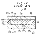
- Fig. 12 is a sectional view illustrating the constitution of a liquid crystal display device 21 of the prior art.
- the liquid crystal display device 21 comprises light transmitting substrates 22, 23, transparent electrodes 24, 25, an adhesive material 26, a liquid crystal layer 27 and polarizing plates 28, 29.
- the light transmitting substrates 22, 23 e.g., made of glass
- the liquid crystal layer 27 is interposed between the substrates 22, 23, which are bonded by the adhesive material 26.
- At least the transparent electrodes 24 are formed on the inner surface of any one of the two substrates 22, 23.
- the substrate 22 is considered as one substrate where the transparent electrodes 24 are formed and the surface 22a is considered as the inner surface.
- the transparent electrodes 24 are of, for example, a segment type shaping a character.
- irregularities are formed on the entire of the inner surface 23a of the other substrate 23 and besides the transparent electrode 25 is formed thereon.
- the transparent electrode 25 is a common electrode which is formed, for example, on the entire of the inner surface 23a of the substrate 23.
- Orientation treatment is applied to the inner surface 22a of the substrate 22 on which the transparent electrode 24 are formed and to the surface of the transparent electrode 25.
- the orientation treatment includes rubbing treatment of a surface coated with an organic material (e.g., polyimide resin) and formation of an inorganic film by oblique evaporation coating.
- Liquid crystal molecules 27a of the liquid crystal layer 27 are oriented in a predetermined direction by the orientation treatment. Further, liquid crystal molecules 27b which are the closest to the irregular surface 23a of the substrate 23 are oriented along the irregularities in one direction as shown in Fig. 12.
- the polarizing plates 28, 29 are arranged on the other surfaces 22b, 23b of the substrates 22, 23, respectively.
- the above-mentioned liquid crystal display device 21 which is disclosed in the Japanese Unexamined Patent Publication (KOKAI) No. JP-A 61-137132 (1986), prevents a coloring phenomenon caused by thickness ununiformity of the liquid crystal layer 27 and color change in relation to a viewing angle.
- a TN-type liquid crystal display device is used as display means for displaying a black-and-white image applied to various equipment mounted on vehicles, and in particular, a transmissive type is preferably applied.
- displaying is carried out by controlling the light entered into a liquid crystal layer from a back light and coloring is caused by the thickness ununiformity of the liquid crystal layer.
- a black-and-white image of high purity can be displayed at a viewing angle of 0°
- the color of the image changes gradually with the increase of the viewing angle.
- it is very disadvantageous that a little different red color is easily caused when a color character should be displayed by virtue of a color background in a specific position of an image plane.
- a red color background is employed by using a backlight of red color group, an unclear reddish character is displayed.
- the coloring phenomenon and color change is prevented by forming irregularities on the surface 23a of the substrate 23. More specifically, since spectrums of almost all colors are caused by virtue of the irregularities, the displayed color is recognized as neutral gray color due to additive color mixture by an observer. Further, the color change in relation to the visual angle is prevented.
- EP-A-0 368 554 relates to a twisted nematic liquid crystal display device comprising a first transparent electrode which has been subjected to orientation treatment in a first direction, a second transparent electrode which has been subjected to orientation treatment in a second direction, a liquid crystal located between said first and second electrodes, a first transparent polarizing plate having a direction of polarization coinciding with the first direction and located outside the first electrode and a second transparent polarizing plate having a direction of polarizing coinciding with the first direction and located outside the second electrode.
- the optical path length difference of the liquid crystal layer which is equal to the product of the thickness of the liquid crystal layer and the double refraction index of the liquid crystal layer has a value such that 1,4 ⁇ m ⁇ ⁇ n d ⁇ 1.7 ⁇ m.
- JP-A-1216318 discloses a liquid crystal display device having a high contrast, a wide visual angle and a more achromatic colour by setting a retardation, i.e. a value of d ⁇ n to a range of ⁇ 1.4 and ⁇ 2,2 and a twist angle to a specific range.
- JP-A-63301023 discloses the addition of a blue dichroic dye to the liquid crystal composition.
- the addition is intended to improve the purity of blue colour in a blue display mode.
- the colour change around blue due to changes in the retardation is compensated by adding the blue dye.
- the dye is added to further improve the blue colour.
- the use of a blue dichroic dye as opposed to a simple blue dye provides for a higher contrast.
- JP-A-62123405 discloses the inclusion (by absorption) of a blue dichroic dye in a polarizer. The disclosure is therefore not relevant to the present device.
- An object of the invention is to provide a liquid crystal display device of improved image quality using a substrate without irregularities.
- the invention provides a liquid crystal display device according to the features of the appended claim 1.
- the color change in relation to a viewing angle is relatively small, and coloring due to the ununiformity of the liquid crystal layer thickness d is hardly caused. Additionally, it is possible to solve the inferior orientation of the liquid crystal molecules, which is caused by irregularities of a substrate, because unlike the prior art, the lowering of color change and coloring can be obtained using a substrate without irregularities.
- the product d ⁇ n is selected from the values in the range of from 1.85 to 1.95 ⁇ m, more improved characteristics are obtainable.
- the angle ⁇ is set to be 0°
- the angle ⁇ is set to be 90° , the most improved characteristics are obtainable.
- each of the pair of polarizing plates comprises a polarizer containing a dyestuff. Since the polarizer is superior to a polarizer containing iodine in thermal resistance, the discolorization of the polarizer due to the use thereof at a relatively higher temperature can be prevented. Accordingly, even when the liquid crystal device is applied to equipment mounted on vehicles, excellent display characteristics can be maintained.
- the liquid crystal layer contains 0.4 to 0.8% pleochroic dye of a blue type.
- the refractive anisotropy ⁇ n of the liquid crystal molecules depends on temperature, namely the refractive anisotropy decreases in correspondence with temperature changes. Consequently, the product d ⁇ n is deviated from the value predetermined. As a result of the deviation of the product d ⁇ n, the displayed color becomes reddish and the display quality is degraded.
- it was demonstrated that such deviation of color is prevented by adding the pleochroic dye of a blue type to the liquid crystal material to be used for the liquid crystal layer, even when the product d ⁇ n is deviated with temperature changes. Consequently, that makes it possible to economically provide a liquid crystal display device of improved display quality. Additionally, a liquid crystal display device with little degradation of display characteristics with temperature changes can be obtained.
- azo- and anthraquinone dye molecules can be used as the blue-type pleochroic dye.
- a pleochroic dye having a relatively high dichroism ratio is preferable in order to enhance the contrast ratio.
- Fig. 1 is a sectional view showing the constitution of a liquid crystal display device 1 of an example not according to the invention.
- the liquid crystal display device 1 comprises polarizing plates 10, 11 and a liquid crystal display element 12, which is disposed between the polarizing plates 10, 11.
- the liquid crystal display element 12 comprises light transmitting substrates 2, 3, transparent electrodes 4, 5, orientation films 6, 7, an adhesive material 8 and a liquid crystal layer 9.
- the transparent electrode 4 and the orientation film 6 are formed so as to be laminated in this order on one surface 2a of the light transmitting substrate 2 (e.g., made of glass).
- the transparent electrode 5 and the orientation film 7 are formed so as to be laminated in this order on one surface 3a of the light transmitting substrate 3 (e.g. made of glass) .
- the transparent electrodes 4, 5 are made of, for example, indium tin oxide (ITO).
- the orientation films 6, 7 are made of, for example, polyimide resin, and have a surface to which orientation treatment such as rubbing treatment is applied.
- the substrates 2, 3 are disposed so that the surfaces 2a, 3a are opposed to each other, and bonded by the adhesive agent 8.
- a twisted nematic liquid crystal material to be used as the liquid crystal layer 9 is injected between the substrates 2, 3 through an injection hole for injecting the liquid crystal and thereafter the injection hole is sealed. Additionally, the arrangement of the substrates 2, 3 and the selection of a liquid crystal material are conducted so that the twist angle ⁇ of liquid crystal molecules between the substrates 2, 3 becomes 90° .
- the product d ⁇ n of the thickness d of the liquid crystal layer 9 and the refractive anisotropy ⁇ n of the liquid crystal molecules is selected from values in the range of from 1.80 to 2.00 ⁇ m and preferably to be in the range of from 1.85 to 1.9 ⁇ m.
- the thickness d of the liquid crystal layer 9 and the refractive anisotropy ⁇ n are 9.5 ⁇ m and 0.1987, respectively. Consequently the product d ⁇ n amounts to 1.888 ⁇ m, which is the most preferable.
- a material having a phase transition temperature (Tni) of 100°C is used as a liquid crystal material. Thereby, the change of ⁇ n (d ⁇ n) due to the change of temperature can be controlled.
- the above-mentioned liquid crystal display element 12 is disposed between the polarizing plates 10, 11.
- An example of the disposition is that the polarizing plate 10 is bonded on the other surface 2b of the substrate 2 and the polarizing plate 11 is bonded on the other surface 3b of the substrate 3.
- the polarizing plates 10, 11 are realized, for example, by a material having a simple substance transmittance of 40% and a polarization of 99.5% or more which is selected from a group of dyestuff materials having a long durability. Giving a concrete example of the polarizing plate, those under the trade names "HC2-61-18S of SANRITZ K.K. and "SF-1822AP" of Sumitomo Chemical Co., Ltd. can be named.
- a polarizing plate with such properties discoloring in an iodine-type polarizing plate, which usually occurs in the environment of a relatively high temperature, can be prevented. Accordingly, the image quality can be prevented from degrading.
- Fig. 2 is a diagram showing a positional relationship of respective composing members of the liquid crystal display device 1.
- Continuous lines P1, P2, P3, P4 show the orientation axis of the liquid crystal molecules closest to the substrate 2, the orientation axis of the liquid crystal molecules closest to the substrate 3, the absorption axis of the polarizing plate 10 and the absorption axis of the polarizing plate 11, respectively.
- the angle ⁇ shows an angle contained by the orientation axis P1 of the liquid crystal molecules closest to the substrate 2 and the absorption axis P3 of the polarizing plate 10
- the angle ⁇ shows an angle contained by the orientation axis P2 of the liquid crystal molecules closest to the substrate 3 and the absorption axis P4 of the polarizing plate 11.
- the angle ⁇ shows an angle contained by the orientation axis P1 and the orientation axis P2, that is the twist angle ⁇ .
- the angle ⁇ , ⁇ and ⁇ were preset to be 0° , 90° , and 90° , respectively.
- the angle ⁇ is preset to be in the range of from -5 to 5° based on the orientation axis P1 of the liquid crystal molecules closest to the substrate 2, and the angle ⁇ is preset to be in the range of from 85 to 95° based on the orientation axis P2 of the liquid crystal molecules closest to the substrate 3. Since the above mentioned product d ⁇ n and the angles ⁇ , ⁇ , ⁇ have operational relations with each other, the desired effect can not be obtained if even one of the preset values is out of the above-mentioned range.
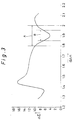
- Fig. 3 is a diagram showing a relationship between d ⁇ n and a color difference ⁇ E.
- the viewing angle ⁇ is assumed to be 0° .
- the color difference ⁇ E was evaluated in a viewing angle direction having the greatest color difference among viewing angle directions in a range of from 0° to 50° . It is estimated that the color difference ⁇ E will become small when the product d ⁇ n is selected from values in the range of from 1.80 to 2.00 ⁇ m (A), in particular, from 1.85 to 1.95 ⁇ m (B), and therefore the color change of an image will become small , because the color difference ⁇ E comes to the smallest when the product d ⁇ n is 1.9 ⁇ m.
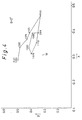
- Figs. 4-6 are chromaticity diagrams with the change of the product d ⁇ n of a liquid crystal layer thickness d and a liquid crystal molecule refractive anisotropy ⁇ n at viewing angles ⁇ of 0° , 25° , and 50° , respectively.
- a back light (e.g., realized by a tungsten lamp) is disposed, for example, on a side opposite to the liquid crystal display element 12 of the polarizing plate 11 and color changes between the directions of 12 to 6 o'clock (up and down direction) and 9 to 3 o'clock (right and left direction) were measured.
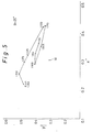
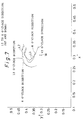
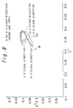
- Fig. 7 is a chromaticity diagram in the direction of 12 to 6 o'clock and Fig. 8 is that in the direction of 9 to 3 o'clock.
- Continuous lines L1, L3 represent the results of the liquid crystal display device 1 and dashed lines L2, L4 represent the results of a liquid crystal display device for a comparative example.
- the liquid crystal display device for a comparative example is provided with substrates having irreguralities as shown in Fig. 11.
- the region where both of X- and Y-coordinates are above those of the white point W represents the region of colors belonging to a yellow color group.
- the region where both of X and Y coordinates are below those of the white point W represents the region of colors belonging to a blue color group.
- the region where an X-coordinate is below that of the white point W and a Y-coordinate is above that of the white point W represents the region of colors belonging to a green color group and the region to the contrary represents the region of colors belonging to a red color group.
- Figs. 7, 8 represent that the degree of color change depending on the viewing angle in the liquid crystal display device 1 is lower than or the same as that in the comparative example of the liquid crystal display device. From this it may be concluded that coloring due to the ununiform thicknesses of the liquid crystal layer 9 hardly occurs in the liquid crystal display device 1. Additionally, since the coloring degree can be reduced without employing a substrate having irregularities unlike a conventional liquid crystal display device, inferior orientation of liquid crystal molecules due to the irregularities can be eliminated. Furthermore, according to the invention, since a relatively expensive substrate such as ground glass is not needed, the liquid crystal display device with an improved display quality can be economically manufactured.
- the liquid crystal display device 1 of the above example is applied, for example, to display means of the equipment mounted on vehicles, which is often exposed to a relatively high temperature environment (e.g., above 45°C).
- the refractive anisotropy ⁇ n of the liquid crystal molecules of the liquid crystal display device 1 depends on temperature.
- the refractive anisotropy decreases with the increase of temperature.
- the product d ⁇ n is deviated from a value predetermined. That causes, for example, a reddish background color and degradation of display properties.
- the embodiment is directed to preventing the degradation of display properties due to the temperature changes.
- a pleochroic dye of between 0.4 and 0.8% is added to the liquid crystal material to be used for the liquid crystal layer 9 of the liquid crystal display device 1.
- a blue-type pleochroic dye of 0.6% was added, which is manufactured by Sumitomo Chemical Co., Ltd. under the tradename "CLD-506".
- Azo- and anthraquinone dye molecules can be used as the blue-type pleochroic dye.
- the contrast ratio can be improved by using a pleochroic dye with a relatively high dichroism ratio.
- a pleochroic dye of only 0.6% is added for the purpose of reducing the manufacturing cost, the decline in image quality due to temperature changes is the least in the case of an addition of 0.8%.
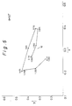
- Fig. 9 is a chromaticity diagram in a direction of 12 to 6 o'clock of the embodiment of a liquid crystal display device
- Fig. 10 is that in a direction of 9 to 3 o'clock.
- the chromaticity diagrams are based on the evaluations in the environment of 65°C.
- Continuous lines L5, L8 represent the results of the embodiment
- alternate long and short dash lines L6, L9 the results of the above device 1
- broken lines L7, L10 the results of the comparative example.
- the display color thereof inclines to red in the use thereof in the environment of a relatively high temperature in both of the up and down and the right and left direction.
- the results for the comparative example using a substrate having irregularities shown by the broken lines L7, L10 prove that the display color thereof does not incline to red and the degree of the color change is low in both the directions.
- the blue-type pleochroic dye is added in order to eliminate the inclination of the display color to red in environment of a high temperature.
- the addition of a larger amount of dye molecules than that mentioned above causes the decrease of light transmittance during voltage application. As a consequence, a display image with a high contrast can not be obtained and besides the manufacturing cost rises due to the increase of the material cost.
- the effect of the invention can not be attained also in the case of a smaller addition amount than that mentioned above.
- Fig. 11 is a chromaticity diagram for a liquid crystal display device with different addition amounts of pleochroic dye of a blue type.
- Continuous lines L11, L12, L13 show the results of liquid crystal display devices having an addition amount of 0.2, 0.6 and 1.0%, respectively.
- continuous line L14 shows the result of the same liquid crystal display device as the comparative example in the above device 1.
- the addition amount of pleochroic dye molecules is preferably selected from values in the above-mentioned range of from 0.4 to 0.8%.
Claims (7)
- Flüssigkristall-Anzeigevorrichtung (1) mit:einer ersten (10) und einer zweiten (11) Polarisationsplatte;einem ersten (2) und einem zweiten (3) lichtdurchlässigen Substrat, die zwischen dem Paar von Polarisationsplatten (10, 11) angeordnet sind; undeiner Flüssigkristallschicht (9), die zwischen dem Paar lichtdurchlässiger Substrate (2, 3) angeordnet ist und die aus Flüssigkristallmolekülen mit einem Verdrillungsausrichtungswinkel von 90° zwischen dem Paar lichtdurchlässiger Substrate (2, 3) besteht;wobei der Winkel α zwischen der ersten Ausrichtungsachse (P1) der Flüssigkristallmoleküle, die am nächsten am ersten lichtdurchlässigen Substrat (2) liegen, und der Absorptionsachse (P3) der ersten Polarisationsplatte (10), die auf der Seite des ersten lichtdurchlässigen Substrats (2) liegt, im Bereich von -5 bis 5° eingestellt ist; undwobei der Winkel β zwischen der zweiten Ausrichtungsachse (P2) der Flüssigkristallmoleküle, die am nächsten am zweiten lichtdurchlässigen Substrat (3) liegen, und der Absorptionsachse (P4) der zweiten Polarisationsplatte (11), die auf der Seite des zweiten lichtdurchlässigen Substrats (3) liegt, im Bereich von 85° bis 95° eingestellt ist;
dadurch gekennzeichnet, dasseine Hintergrundbeleuchtungs-Lichtquelle mit einer Wolframlampe auf der Seite der zweiten Polarisationsplatte (11), die vom zweiten lichtdurchlässigen Substrat (3) abgewandt ist, angeordnet ist, um einen Anzeigevorgang der Flüssigkristall-Anzeigevorrichtung (1) zu bewirken;das Produkt d·Δn aus der Dicke d der Flüssigkristallschicht und der Brechungsanisotropie Δn der Flüssigkristallmoleküle aus Werten im Bereich von 1,80 bis 2,00 µm ausgewählt ist; unddie Flüssigkristallschicht (9) einen Pleochroitischen Farbstoff von blauem Typ mit einer Menge im Bereich von 0,4 bis 0,8% bezogen auf die Gesamtmenge der Flüssigkristallschicht (9) enthält, um zu verhindern, dass die Anzeigefarbe bei erhöhter Umgebungstemperatur von über 45°C auf rot wechselt. - Flüssigkristall-Anzeigevorrichtung (1) nach Anspruch 1, bei der die Menge des pleochroitischen Farbstoffs von blauem Typ 0,8% bezogen auf die Gesamtmenge der Flüssigkristallschicht (9) beträgt.
- Flüssigkristall-Anzeigevorrichtung (1) nach Anspruch 1, bei der der pleochroitische Farbstoff von blauem Typ aus Azo-Farbstoffmolekülen besteht.
- Flüssigkristall-Anzeigevorrichtung (1) nach Anspruch 1, bei der der pleochroitische Farbstoff von blauem Typ aus Antrachinon-Farbstoffmolekülen besteht.
- Flüssigkristall-Anzeigevorrichtung (1) nach Anspruch 1, bei der das Produkt d·Δn aus Werten im Bereich 1,85 bis 1,95 µm ausgewählt ist.
- Flüssigkristall-Anzeigevorrichtung (1) nach Anspruch 1, bei der das Produkt d·Δn den Wert 1,888 µm hat und die Winkel α, β auf 0° bzw. 90° eingestellt sind.
- Flüssigkristall-Anzeigevorrichtung (1) nach Anspruch 1, bei der jedes Paar von Polarisationsplatten (10, 11) ein Substrat aufweist, das einen im Substrat adsorbierten Farbstoff enthält.
Applications Claiming Priority (3)
| Application Number | Priority Date | Filing Date | Title |
|---|---|---|---|
| JP19374193 | 1993-08-04 | ||
| JP5193741A JP2933258B2 (ja) | 1993-08-04 | 1993-08-04 | 液晶表示装置 |
| JP193741/93 | 1993-08-04 |
Publications (2)
| Publication Number | Publication Date |
|---|---|
| EP0637773A1 EP0637773A1 (de) | 1995-02-08 |
| EP0637773B1 true EP0637773B1 (de) | 2000-05-10 |
Family
ID=16313042
Family Applications (1)
| Application Number | Title | Priority Date | Filing Date |
|---|---|---|---|
| EP19940112131 Expired - Lifetime EP0637773B1 (de) | 1993-08-04 | 1994-08-03 | Flüssigkristall-Anzeigevorrichtung |
Country Status (4)
| Country | Link |
|---|---|
| EP (1) | EP0637773B1 (de) |
| JP (1) | JP2933258B2 (de) |
| DE (1) | DE69424349T2 (de) |
| TW (1) | TW265422B (de) |
Families Citing this family (6)
| Publication number | Priority date | Publication date | Assignee | Title |
|---|---|---|---|---|
| JP2001147414A (ja) * | 1999-11-22 | 2001-05-29 | Stanley Electric Co Ltd | Tn形液晶表示装置 |
| JP4603141B2 (ja) * | 2000-09-29 | 2010-12-22 | オプトレックス株式会社 | 液晶表示装置 |
| JP4634594B2 (ja) * | 2000-10-27 | 2011-02-16 | オプトレックス株式会社 | 液晶表示装置 |
| JP2010128177A (ja) * | 2008-11-27 | 2010-06-10 | Stanley Electric Co Ltd | 液晶表示素子 |
| JP5952038B2 (ja) * | 2012-03-15 | 2016-07-13 | スタンレー電気株式会社 | 液晶表示素子 |
| JP5958091B2 (ja) * | 2012-05-31 | 2016-07-27 | 日本精機株式会社 | 液晶表示素子 |
Family Cites Families (6)
| Publication number | Priority date | Publication date | Assignee | Title |
|---|---|---|---|---|
| DE3244248A1 (de) * | 1982-11-30 | 1984-05-30 | Robert Bosch Gmbh, 7000 Stuttgart | Verfahren zur reduzierung der resttransmission bei lcd-anzeigen |
| CA1269555A (en) * | 1984-11-16 | 1990-05-29 | Sumitomo Chemical Company, Limited | Light-polarizing film |
| JPS62133427A (ja) * | 1985-12-06 | 1987-06-16 | Toshiba Corp | 液晶表示器 |
| JPS63301023A (ja) * | 1987-05-30 | 1988-12-08 | Ricoh Co Ltd | 液晶表示素子 |
| JPH01216318A (ja) * | 1988-02-24 | 1989-08-30 | Alps Electric Co Ltd | 液晶素子 |
| JPH02130521A (ja) * | 1988-11-11 | 1990-05-18 | Nippon I B M Kk | ツイステッド・ネマチック液晶表示装置 |
-
1993
- 1993-08-04 JP JP5193741A patent/JP2933258B2/ja not_active Expired - Fee Related
-
1994
- 1994-07-22 TW TW83106734A patent/TW265422B/zh not_active IP Right Cessation
- 1994-08-03 DE DE1994624349 patent/DE69424349T2/de not_active Expired - Lifetime
- 1994-08-03 EP EP19940112131 patent/EP0637773B1/de not_active Expired - Lifetime
Also Published As
| Publication number | Publication date |
|---|---|
| DE69424349D1 (de) | 2000-06-15 |
| JP2933258B2 (ja) | 1999-08-09 |
| DE69424349T2 (de) | 2000-12-14 |
| TW265422B (de) | 1995-12-11 |
| JPH0749498A (ja) | 1995-02-21 |
| EP0637773A1 (de) | 1995-02-08 |
Similar Documents
| Publication | Publication Date | Title |
|---|---|---|
| JP3339334B2 (ja) | 反射型液晶表示素子 | |
| US5124824A (en) | Liquid crystal display device comprising a retardation compensation layer having a maximum principal refractive index in the thickness direction | |
| KR920006928B1 (ko) | 액정 디스플레이 장치 | |
| US5179457A (en) | Liquid crystal display device with birefringent film between the substrates of the liquid crystal | |
| EP1014161B1 (de) | Reflektierende flüssigkristallanzeige | |
| JP3292809B2 (ja) | カラー液晶表示素子 | |
| US6359671B1 (en) | High contrast liquid crystal device | |
| JP3204260B2 (ja) | 反射型カラー液晶表示装置 | |
| US6144432A (en) | Reflective liquid crystal display device | |
| EP0498614A2 (de) | Flüssigkristallanzeigevorrichtung | |
| US5448386A (en) | Optical liquid crystal element | |
| US6933994B1 (en) | Liquid crystal display including an anisotropic scattering layer | |
| KR100385691B1 (ko) | 반사형 액정표시소자 | |
| EP0978753A2 (de) | Flüssigkristallanzeigeelement vom Reflexionstyp | |
| US6072553A (en) | Reflection-type liquid crystal display with layer comprising liquid crystal compound and liquid crystal polymer being twist-aligned at same angle | |
| KR100306648B1 (ko) | 반사형 액정표시 소자 | |
| JPH02124529A (ja) | 二層型液晶表示装置 | |
| EP0637773B1 (de) | Flüssigkristall-Anzeigevorrichtung | |
| KR20010042793A (ko) | 반사형 액정표시소자 | |
| JP3143271B2 (ja) | 液晶表示装置 | |
| JP2768319B2 (ja) | カラー液晶表示素子 | |
| KR100303715B1 (ko) | 액정 표시 장치 | |
| JP3399463B2 (ja) | カラ−液晶表示素子 | |
| JP2869452B2 (ja) | 液晶表示素子 | |
| JPH0311317A (ja) | 液晶表示装置 |
Legal Events
| Date | Code | Title | Description |
|---|---|---|---|
| PUAI | Public reference made under article 153(3) epc to a published international application that has entered the european phase |
Free format text: ORIGINAL CODE: 0009012 |
|
| AK | Designated contracting states |
Kind code of ref document: A1 Designated state(s): DE GB IT |
|
| 17P | Request for examination filed |
Effective date: 19950505 |
|
| 17Q | First examination report despatched |
Effective date: 19961227 |
|
| GRAG | Despatch of communication of intention to grant |
Free format text: ORIGINAL CODE: EPIDOS AGRA |
|
| GRAG | Despatch of communication of intention to grant |
Free format text: ORIGINAL CODE: EPIDOS AGRA |
|
| GRAH | Despatch of communication of intention to grant a patent |
Free format text: ORIGINAL CODE: EPIDOS IGRA |
|
| GRAH | Despatch of communication of intention to grant a patent |
Free format text: ORIGINAL CODE: EPIDOS IGRA |
|
| GRAA | (expected) grant |
Free format text: ORIGINAL CODE: 0009210 |
|
| AK | Designated contracting states |
Kind code of ref document: B1 Designated state(s): DE GB IT |
|
| REF | Corresponds to: |
Ref document number: 69424349 Country of ref document: DE Date of ref document: 20000615 |
|
| ITF | It: translation for a ep patent filed |
Owner name: RACHELI & C. S.R.L. |
|
| EN | Fr: translation not filed | ||
| PLBE | No opposition filed within time limit |
Free format text: ORIGINAL CODE: 0009261 |
|
| STAA | Information on the status of an ep patent application or granted ep patent |
Free format text: STATUS: NO OPPOSITION FILED WITHIN TIME LIMIT |
|
| 26N | No opposition filed | ||
| REG | Reference to a national code |
Ref country code: GB Ref legal event code: IF02 |
|
| PGFP | Annual fee paid to national office [announced via postgrant information from national office to epo] |
Ref country code: GB Payment date: 20110803 Year of fee payment: 18 Ref country code: DE Payment date: 20110727 Year of fee payment: 18 |
|
| PGFP | Annual fee paid to national office [announced via postgrant information from national office to epo] |
Ref country code: IT Payment date: 20110812 Year of fee payment: 18 |
|
| GBPC | Gb: european patent ceased through non-payment of renewal fee |
Effective date: 20120803 |
|
| PG25 | Lapsed in a contracting state [announced via postgrant information from national office to epo] |
Ref country code: IT Free format text: LAPSE BECAUSE OF NON-PAYMENT OF DUE FEES Effective date: 20120803 |
|
| PG25 | Lapsed in a contracting state [announced via postgrant information from national office to epo] |
Ref country code: DE Free format text: LAPSE BECAUSE OF NON-PAYMENT OF DUE FEES Effective date: 20130301 Ref country code: GB Free format text: LAPSE BECAUSE OF NON-PAYMENT OF DUE FEES Effective date: 20120803 |
|
| REG | Reference to a national code |
Ref country code: DE Ref legal event code: R119 Ref document number: 69424349 Country of ref document: DE Effective date: 20130301 |