EP0637398B1 - Einrichtung zur optischen abtastung eines aufzeichnungsträgers, insbesondere einer phosphorspeicherplatte - Google Patents
Einrichtung zur optischen abtastung eines aufzeichnungsträgers, insbesondere einer phosphorspeicherplatte Download PDFInfo
- Publication number
- EP0637398B1 EP0637398B1 EP93911506A EP93911506A EP0637398B1 EP 0637398 B1 EP0637398 B1 EP 0637398B1 EP 93911506 A EP93911506 A EP 93911506A EP 93911506 A EP93911506 A EP 93911506A EP 0637398 B1 EP0637398 B1 EP 0637398B1
- Authority
- EP
- European Patent Office
- Prior art keywords
- cavity
- scanning
- recording medium
- scanning beam
- mirror
- Prior art date
- Legal status (The legal status is an assumption and is not a legal conclusion. Google has not performed a legal analysis and makes no representation as to the accuracy of the status listed.)
- Expired - Lifetime
Links
Images
Classifications
-
- H—ELECTRICITY
- H01—ELECTRIC ELEMENTS
- H01J—ELECTRIC DISCHARGE TUBES OR DISCHARGE LAMPS
- H01J37/00—Discharge tubes with provision for introducing objects or material to be exposed to the discharge, e.g. for the purpose of examination or processing thereof
- H01J37/02—Details
- H01J37/22—Optical, image processing or photographic arrangements associated with the tube
- H01J37/224—Luminescent screens or photographic plates for imaging; Apparatus specially adapted therefor, e. g. cameras, TV-cameras, photographic equipment or exposure control; Optical subsystems specially adapted therefor, e. g. microscopes for observing image on luminescent screen
-
- G—PHYSICS
- G06—COMPUTING OR CALCULATING; COUNTING
- G06K—GRAPHICAL DATA READING; PRESENTATION OF DATA; RECORD CARRIERS; HANDLING RECORD CARRIERS
- G06K7/00—Methods or arrangements for sensing record carriers, e.g. for reading patterns
- G06K7/10—Methods or arrangements for sensing record carriers, e.g. for reading patterns by electromagnetic radiation, e.g. optical sensing; by corpuscular radiation
-
- G—PHYSICS
- G11—INFORMATION STORAGE
- G11B—INFORMATION STORAGE BASED ON RELATIVE MOVEMENT BETWEEN RECORD CARRIER AND TRANSDUCER
- G11B7/00—Recording or reproducing by optical means, e.g. recording using a thermal beam of optical radiation by modifying optical properties or the physical structure, reproducing using an optical beam at lower power by sensing optical properties; Record carriers therefor
- G11B7/002—Recording, reproducing or erasing systems characterised by the shape or form of the carrier
- G11B7/0033—Recording, reproducing or erasing systems characterised by the shape or form of the carrier with cards or other card-like flat carriers, e.g. flat sheets of optical film
-
- G—PHYSICS
- G11—INFORMATION STORAGE
- G11B—INFORMATION STORAGE BASED ON RELATIVE MOVEMENT BETWEEN RECORD CARRIER AND TRANSDUCER
- G11B7/00—Recording or reproducing by optical means, e.g. recording using a thermal beam of optical radiation by modifying optical properties or the physical structure, reproducing using an optical beam at lower power by sensing optical properties; Record carriers therefor
- G11B7/12—Heads, e.g. forming of the optical beam spot or modulation of the optical beam
- G11B7/123—Integrated head arrangements, e.g. with source and detectors mounted on the same substrate
-
- G—PHYSICS
- G11—INFORMATION STORAGE
- G11C—STATIC STORES
- G11C13/00—Digital stores characterised by the use of storage elements not covered by groups G11C11/00, G11C23/00, or G11C25/00
- G11C13/04—Digital stores characterised by the use of storage elements not covered by groups G11C11/00, G11C23/00, or G11C25/00 using optical elements ; using other beam accessed elements, e.g. electron or ion beam
Definitions
- the invention relates to a device with the features listed in the preamble of claim 1, which results from a publication by Mori et al., J. Electron. Microsc. 39; 433-436 (1990) are known.
- IP reader contains a He-Ne laser for generating a scanning beam which falls along a scanning beam path through a partially transparent mirror onto a deflecting mirror and is then focused onto a scanning location by a lens which the phosphor storage plate is moved past by a coordinate table.
- the scanning beam generates a fluorescent radiation representing the stored information at the location of the phosphor storage plate at the scanning location, which after collimation is reflected by the focusing lens from the deflecting mirror and from the partially transparent mirror and is focused by a second lens into the opening of a diaphragm, behind which a photomultiplier is arranged is.
- the aperture is required to laterally discriminate the luminescence signal from the storage disk. In this way, the resolution of the reading system is increased.
- the present invention is based on this prior art, the object of specifying a device with the features listed in the preamble of claim 1, in which a much larger part of the useful radiation generated by the scanning beam at the scanning location can be detected by the photodetector and at the same time a very high lateral spatial resolution is achieved.
- the present device is characterized by an essentially confocal optical mirror system with a very high aperture, which detects a very large part of the useful radiation generated during reading and transmits it to the photodetector practically without loss. Due to the imaging property of the mirror system, the laser radiation scattered back from the entrance window of the photodetector (SEV) or from a color glass filter connected upstream of it can be absorbed in a further concave mirror designed as a beam trap, which adjoins the actual imaging mirror system. The sensitivity and resolution are high.
- a preferred device for querying the information stored in a phosphor storage disk uses a laser scanning beam, the intensity of which is significant is higher than that of the laser reading beam of the known phosphor storage disk reading devices.
- a He-Ne laser with a continuous wave power of more than 10 mW, in particular more than 15 mW can be used.
- the high power can only be used meaningfully because the imaging property of the mirror system very strongly suppresses the laser light reflected back from the color filter and / or the entrance window of the photodetector onto the storage plate.
- the device according to the invention is particularly suitable for optical scanning of phosphor storage disks and is therefore explained below with reference to this application.
- the invention is not limited to readers for phosphor storage disks, but can also be used for reading other record carriers in which information is stored in an optically readable form.
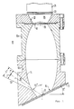
- the optical system of a scanning head 10 is essentially shown in axial section, which is used for optically scanning a phosphor storage disk 12.
- the scanning head 10 is displaceable with respect to the storage disk 12, e.g. B. by one of the two elements and the other is connected to a suitable drive, such as a stepper motor-controlled coordinate drive (not shown).
- the scanning head 10 consists of two hollow parts 10a, 10b which are screwed to one another and forms a cavity on the inside in the form of an elongated ellipsoid of revolution, which in the illustrated embodiment has a small semi-axis of 20 mm and a large semi-axis of about 48 mm.
- the inner wall of the cavity forms an ellipsoidal mirror 14.
- the end of the ellipsoid facing the storage plate 12 is cut obliquely at an angle of 25 degrees to the long axis of the ellipsoid in order to form an entry opening 16 through which the useful radiation generated when the storage plate is read, So here fluorescence radiation can enter the cavity delimited by the mirror 14.
- the storage plate 12 is held parallel to the plane of the inlet opening 16 at the latter.
- the upper end of the cavity is cut straight to form an exit opening 18 for the useful radiation.
- the outlet opening 18 is adjoined by an expanding cavity 20 with a reflecting inner wall 22, at the opening opposite the outlet opening 18 a photomultiplier (SEV) 24 serving as a photodetector is arranged.
- SEV photomultiplier
- a diaphragm can be arranged between the outlet opening 18 and the cavity 20, which laterally discriminates the useful radiation, ie here a blue fluorescent radiation, and thus increases the spatial resolution.
- a colored glass filter 33 is arranged between the photomultiplier 24 and the cavity 20, which only transmits useful radiation, that is to say the blue luminescent light, while it absorbs the red laser radiation and / or reflects it into the cavity. while it blocks the scanning radiation, here red laser radiation.
- a channel 28 for a scanning beam 30 that widens slightly conically on the outside.
- the channel here has an opening angle of 14 degrees and the beam path of the scanning beam 30 forms an angle of 55 degrees with the long axis of the ellipsoid, so that the scanning beam does not fall too obliquely onto the surface of the storage disk, which is also at an angle for this reason Longitudinal axis of the mirror 14 is arranged.
- the inlet opening 16 had a diameter of 21 mm
- the outlet opening 18 had a diameter of 16.5 mm
- the component forming the cavity 20 had an axial dimension of 12 mm and an opening facing the photomultiplier with a diameter of approximately 29 , 5 mm.
- the reading or scanning beam 30 generated by a He-Ne laser falls on the phosphor storage plate 12 at a scanning location 32 and produces a generally blue fluorescent radiation, the intensity of which depends on the information stored at the relevant location. Because of the very high aperture of the mirror system, which is above 0.9 in practice, this useful radiation is essentially completely collected by the optical mirror system and focused in the middle of the plane of the outlet opening 18.
- Unwanted stray radiation which arises from scattering of the scanning beam in the multicrystalline phosphor storage plate 12, is absorbed by the color filter 26 and / or attenuated by multiple reflection in the cavity 20 to such an extent that the scattered radiation only reaches the ellipsoidal cavity in a very strongly weakened manner and therefore no laser intensity acts outside the location 32 on the storage disk.
- a useful signal ie fluorescence radiation, is generated only at location 32, which increases the resolution of the reading system.
- the elongated ellipsoidal mirror 14 described represents an optimal implementation of the confocal mirror imaging system used here. Since apart from the color filter 26, which is not required in many cases, and the light entry surface of the photomultiplier 24, no interfaces have to be penetrated by the fluorescent light, the optical losses are minimal .
- mirror systems can also be used, e.g. B. a mirror in the form of a three-axis ellipsoid, also two paraboloid of revolution, which face each other with their large openings or other mirror systems, which cause at least approximately a confocal image of the scanning location 32 in the relatively large outlet opening 18.
- the inner wall 22 of the cavity 20 can have the shape of part of an ellipsoid of revolution, but the only thing that is important is that it widens somewhat from the outlet opening 18.
- the axial length of the cavity 20 will generally be less than the diameter of the outlet opening 18 and this in turn will generally be less than the diameter of the inlet opening 16.
- Surfaces 14 and 22 can be made by turning with a diamond tool.
- a scanning beam 30 can be used in the present device with a much higher intensity than in the known devices of the present type.
- a He-Ne laser beam with a power of 16 mW was used. The increase in the power of the scanning beam brings with it the significant advantage that the color centers are practically completely erased when scanning, so that the areas of the storage disk that have already been scanned can no longer be excited by interfering scanning radiation to form an interfering fluorescence which would impair the resolution.
Landscapes
- Physics & Mathematics (AREA)
- Engineering & Computer Science (AREA)
- Computer Vision & Pattern Recognition (AREA)
- Chemical & Material Sciences (AREA)
- General Health & Medical Sciences (AREA)
- Toxicology (AREA)
- Health & Medical Sciences (AREA)
- Artificial Intelligence (AREA)
- Optics & Photonics (AREA)
- General Physics & Mathematics (AREA)
- Theoretical Computer Science (AREA)
- Electromagnetism (AREA)
- Analytical Chemistry (AREA)
- Facsimile Scanning Arrangements (AREA)
- Conversion Of X-Rays Into Visible Images (AREA)
- Image Input (AREA)
- Optical Head (AREA)
- Radiography Using Non-Light Waves (AREA)
- Investigating, Analyzing Materials By Fluorescence Or Luminescence (AREA)
Abstract
Description
- Die Erfindung geht aus von einer Einrichtung mit den im Oberbegriff des Anspruchs 1 aufgeführten Merkmalen, die aus einer Veröffentlichung von Mori et al., J. Electron. Microsc. 39; 433-436 (1990) bekannt sind.
- Die aus der obengenannten Veröffentlichung bekannte Einrichtung ("IP-Lesegerät") enthält einen He-Ne-Laser zur Erzeugung eines Abtaststrahles, der längs eines Abtaststrahlenganges durch einen teildurchlässigen Spiegel auf einen Umlenkspiegel fällt und dann durch eine Linse auf einen Abtastort fokussiert wird, an dem die Phosphorspeicherplatte durch einen Koordinatentisch vorbeibewegt wird. Der Abtaststrahl erzeugt an der sich am Abtastort befindenden Stelle der Phosphorspeicherplatte eine die gespeicherte Information darstellende Fluoreszenzstrahlung, die nach Kollimierung durch die Fokussierungslinse vom Umlenkspiegel und vom teildurchlässigen Spiegel reflektiert und durch eine zweite Linse in die Öffnung einer Blende fokussiert wird, hinter der ein Fotomultiplier angeordnet ist. Die Blende ist erforderlich, um das Lumineszenzsignal von der Speicherplatte lateral zu diskriminieren. Auf diese Weise wird die Auflösung des Lesesystems erhöht.
- Wegen der relativ begrenzten Apertur der Fokussierungslinse und den optischen Verlusten, die durch die Linsen und Spiegel im Strahlengang der Lesestrahlung verursacht werden und schließlich wegen der Blende gelangt nur ein relativ kleiner Teil der Fluoreszenzstrahlung zum Fotomultiplier, so daß das Verhältnis von Nutzsignal zu Störsignal am Ausgang des Fotomultipliers zu wünschen übrig läßt.
- Der vorliegenden Erfindung liegt, ausgehend von diesem Stand der Technik, die Aufgabe zugrunde, eine Einrichtung mit den im Oberbegriff des Anspruchs 1 aufgeführten Merkmalen anzugeben, bei der ein wesentlich größerer Teil der vom Abtaststrahl am Abtastort erzeugten Nutzstrahlung durch den Fotodetektor erfaßt werden kann und gleichzeitig eine sehr hohe laterale Ortsauflösung erreicht wird.
- Diese Aufgabe wird durch die im Patentanspruch 1 gekennzeichnete Einrichtung gelöst. Weiterbildungen und vorteilhafte Ausgestaltungen dieser erfindungsgemäßen Einrichtung sind Gegenstand von Unteransprüchen.
- Die vorliegende Einrichtung zeichnet sich durch ein im wesentlichen konfokales optisches Spiegelsystem sehr hoher Apertur aus, das einen sehr großen Teil der beim Lesen erzeugten Nutzstrahlung erfaßt und praktisch verlustfrei zum Photodetektor weiterleitet. Durch die abbildende Eigenschaft des Spiegelsystems kann die vom Eintrittsfenster des Photodetektors (SEV) oder von einem diesem vorgeschalteten Farbglasfilter zurückgestreute Laserstrahlung in einem als Strahlenfalle ausgelegten weiteren Hohlspiegel, der sich an das eigentliche abbildende Spiegelsystem anschließt, absorbiert werden. Die Empfindlichkeit und das Auflösungsvermögen sind hoch..
- Bei einer bevorzugten Einrichtung zum Abfragen der in einer Phosphorspeicherplatte gespeicherten Information wird ein Laserabtaststrahl verwendet, dessen Intensität wesentlich höher ist als die des Laser-Lesestrahles der bekannten Phosphorspeicherplatten-Lesegeräte. Beispielsweise kann ein He-Ne-Laser mit einer Dauerstrichleistung von mehr als 10 mW, insbesondere mehr als 15 mW verwendet werden. Die hohe Leistung ist erst dadurch sinnvoll einsetzbar, daß durch die abbildende Eigenschaft des Spiegelsystems das vom Farbfilter und/oder dem Eintrittsfenster des Photodetektors auf die Speicherplatte zurückgestrahlte Laserlicht sehr stark unterdrückt wird.
- Die Einrichtung gemäß der Erfindung eignet sich insbesondere zur optischen Abtastung von Phosphorspeicherplatten und wird daher im folgenden anhand dieser Anwendung erläutert. Die Erfindung ist jedoch nicht auf Lesegeräte für Phosphorspeicherplatten beschränkt, sondern kann auch zum Lesen anderer Aufzeichnungsträger verwendet werden, in denen Information in optisch lesbarer Form gespeichert ist.
- Im folgenden wird die Erfindung anhand eines bevorzugten Ausführungsbeispieles unter Bezugnahme auf die Zeichnung näher erläutert, deren einzige Figur einen Axialschnitt der für die Erfindung wesentlichen Teile einer Einrichtung zur optischen Abtastung einer Phosphorspeicherplatte zeigt.
- In der Zeichnung ist im Axialschnitt im wesentlichen das optische System eines Abtastkopfes 10 dargestellt, der zum optischen Abtasten einer Phosphorspeicherplatte 12 dient. Der Abtastkopf 10 ist bezüglich der Speicherplatte 12 verschiebbar, z. B. indem eines der beiden Elemente fest gelagert und das andere mit einem geeigneten Antrieb, wie einem schrittmotorgesteuerten Koordinatenantrieb verbunden ist (nicht dargestellt).
- Der Abtastkopf 10 besteht aus zwei miteinander verschraubten hohlen Teilen 10a, 10b und bildet innen einen Hohlraum in Form eines langgestreckten Rotationsellipsoids, das bei dem dargestellten Ausführungsbeispiel eine kleine Halbachse von 20 mm und eine große Halbachse von etwa 48 mm hat. Die Innenwand des Hohlraumes bildet einen ellipsoidförmigen Spiegel 14. Das der Speicherplatte 12 zugewandte Ende des Ellipsoids ist unter einem Winkel von 25 Grad zur langen Achse des Ellipsoids schräg abgeschnitten, um eine Eintrittsöffnung 16 zu bilden, durch die die beim Lesen der Speicherplatte entstehende Nutzstrahlung, also hier Fluoreszenzstrahlung, in den durch den Spiegel 14 begrenzten Hohlraum eintreten kann. Die Speicherplatte 12 ist parallel zur Ebene der Eintrittsöffnung 16 bei dieser gehaltert.
- Das obere Ende des Hohlraumes ist gerade abgeschnitten, um eine Austrittsöffnung 18 für die Nutzstrahlung zu bilden. An die Austrittsöffnung 18 schließt sich ein sich erweiternder Hohlraum 20 mit spiegelnder Innenwand 22 an, an dessen der Austrittsöffnung 18 entgegengesetzten Öffnung ein als Fotodetektor dienender Fotomultiplier (SEV) 24 angeordnet ist.
- Zwischen der Austrittsöffnung 18 und dem Hohlraum 20 kann eine Blende angeordnet werden, die die Nutzstrahlung, also hier eine blaue Fluoreszenzstrahlung, lateral diskriminiert und somit die Ortsauflösung erhöht. Zwischen dem Photomultiplier 24 und dem Hohlraum 20 ist ein Farbglasfilter 33 angeordnet, das nur Nutzstrahlung, also das blaue Lumineszenzlicht, transmittiert während es die rote Laserstrahlung absorbiert und/oder in den Hohlraum reflektiert. während es die Abtaststrahlung, hier rote Laserstrahlung, sperrt.
- Im unteren Teil 10b des Abtastkopfes 10 ist ein sich außen schwach konisch erweiternder Kanal 28 für einen Abtaststrahl 30 vorgesehen. Der Kanal hat hier einen Öffnungswinkel von 14 Grad und der Strahlengang des Abtaststrahls 30 bildet einen Winkel von 55 Grad mit der langen Achse des Ellipsoids, so daß der Abtaststrahl nicht zu schräg auf die Oberfläche der Speicherplatte fällt, die auch aus diesem Grund im Winkel zur Längsachse des Spiegels 14 angeordnet ist.
- Die Eintrittsöffnung 16 hatte bei dem dargestellten Ausführungsbeispiel einen Durchmesser von 21 mm, die Austrittsöffnung 18 einen Durchmesser von 16,5 mm, das den Hohlraum 20 bildende Bauteil hatte eine axiale Abmessung von 12 mm und eine dem Fotomultiplier zugewandte Öffnung mit einem Durchmesser von etwa 29,5 mm. Diese und die oben erwähnten Parameter, Maße und Winkel sind selbstverständlich nicht einschränkend auszulegen.
- Im Betrieb fällt der von einem nicht dargestellten He-Ne-Laser erzeugte Lese- oder Abtaststrahl 30 an einem Abtastort 32 auf die Phosphorspeicherplatte 12 und läßt dort eine im allgemeinen blaue Fluoreszenzstrahlung entstehen, deren Intensität von der an der betreffenden Stelle gespeicherten Information abhängt. Diese Nutzstrahlung wird wegen der sehr hohen Apertur des Spiegelsystems, die in der Praxis über 0,9 liegt, vom optischen Spiegelsystem im wesentlichen vollständig gesammelt und in die Mitte der Ebene der Austrittsöffnung 18 fokussiert. Unerwünschte Streustrahlung, die durch Streuung des Abtaststrahles in der multikristallinen Phosphorspeicherplatte 12 entsteht, wird durch das Farbfilter 26 absorbiert und/oder durch Mehrfachreflexion im Hohlraum 20 so weit abgeschwächt, daß die Streustrahlung nur noch sehr stark geschwächt in den ellipsoidförmigen Hohlraum gelangt und somit keine Laserintensität außerhalb des Ortes 32 auf die Speicherplatte einwirkt. Dadurch wird nur am Ort 32 ein Nutzsignal, also Fluoreszenzstrahlung, erzeugt wodurch die Auflösung des Lesesystems erhöht wird.
- Der beschriebene langgestreckte ellipsoidförmige Spiegel 14 stellt eine optimale Realisierung des hier angewandten konfokalen Spiegelabbildungssystems dar. Da außer dem Farbfilter 26, das in vielen Fällen nicht benötigt wird, und der Lichteintrittsfläche des Fotomultipliers 24 vom Fluoreszenzlicht keine Grenzflächen durchsetzt werden müssen, sind die optischen Verluste minimal.
- Anstelle des beschriebenen rotationsellipsoidförmigen Spiegels können jedoch auch andere Spiegelsysteme verwendet werden, z. B. ein Spiegel in Form eines dreiachsigen Ellipsoids, ferner zwei Rotationsparaboloide, die sich mit ihren großen Öffnungen gegenüberstehen oder auch andere Spiegelsysteme, welche wenigstens annähernd eine konfokale Abbildung des Abtastortes 32 in die relativ große Austrittsöffnung 18 bewirken.
- Die Innenwand 22 des Hohlraumes 20 kann die Form eines Teiles eines Rotationsellipsoids haben, wesentlich ist jedoch nur, daß sie sich von der Austrittsöffnung 18 aus etwas erweitert. Die axiale Länge des Hohlraumes 20 wird im allgemeinen kleiner als der Durchmesser der Austrittsöffnung 18 sein und dieser wird wiederum im allgemeinen kleiner als der Durchmesser der Eintrittsöffnung 16 sein.
- Die Flächen 14 und 22 können durch Drehen mit einem Diamantwerkzeug hergestellt werden.
- Da bei dem vorliegenden konfokalen Abbildungssystem trotz seiner sehr hohen Apertur die Rücktstrahlung des Störsignals, hier die in das ellipsoidförmige Spiegelsystem von der Speicherplatte und dem Farbfilter bzw. Multiplier reflektierte Laserstrahlung durch den Hohlraum 20 stark unterdrückt wird, kann man bei der vorliegenden Einrichtung einen Abtaststrahl 30 mit wesentlich höherer Intensität verwenden, als bei den bekannten Einrichtungen der vorliegenden Art. Bei einer praktischen Ausführungsform der Erfindung wurde ein He-Ne-Laserstrahl mit einer Leistung von 16 mW verwendet. Die Erhöhung der Leistung des Abtaststrahls bringt den wesentlichen Vorteil mit sich, daß die Farbzentren beim Abtasten praktisch völlig gelöscht werden, so daß die schon abgetasteten Bereiche der Speicherplatte durch gestreute Abtaststrahlung auch nicht mehr zu einer Störfluoreszenz angeregt werden können, die die Auflösung beeinträchtigen würde.
Claims (8)
- Einrichtung zur optischen Abtastung eines Aufzeichnungsträgers, insbesondere einer Phosphorspeicherplatte mit einem relativ zum Aufzeichnungsträger (12) beweglichen Abtastkopf (10), der einen Abtaststrahlengang, längs dessen ein Abtaststrahl (30) auf einen vorgegebenen Abtastort (32) fällt, an dem der Aufzeichnungsträger durch die Relativbewegung vorbeibewegbar ist, und ein spiegeloptisches Abbildungssystem, das Nutzstrahlung, die durch den Abtaststrahl (30) am Abtastort (32) erzeugt wird, im wesentlichen in eine Bildebene fokussiert, enthält, und mit einem Fotodetektor (24), der im Wege der Nutzstrahlung im Abstand hinter der Bildebene angeordnet ist, dadurch gekennzeichnet, daß das Abbildungssystem durch eine spiegelnde Innenfläche (14) eines Hohlraumes gebildet wird, der die Form eines langgestreckten Ellipsoids oder zweier einander gegenüberliegender Paraboloide hat und an axial entgegengesetzten Enden eine Lichteintrittsöffnung (16) bzw. eine Lichtaustrittsöffnung (18) aufweist.
- Einrichtung nach Anspruch 1, dadurch gekennzeichnet, daß der Hohlraum (14) die Form eines Rotationsellipsoids hat.
- Einrichtung nach Anspruch 1, 2 oder 3, dadurch gekennzeichnet, daß die Ebene der Eintrittsöffnung (16) schräg zur Längsachse des Hohlraumes verläuft.
- Einrichtung nach einem der vorhergehenden Ansprüche, dadurch gekennzeichnet, daß der Abtastkopf (10) eine schräg zur Längsachse des Hohlraumes verlaufende Öffnung (28) für den Abtaststrahl (30) aufweist.
- Einrichtung nach einem der vorhergehenden Ansprüche, dadurch gekennzeichnet, daß zwischen der Austrittsöffnung (18) des Hohlraumes (14) und dem Fotodetektor (24) ein sich in Ausbreitungsrichtung der Strahlung erweiternder Hohlraum (20) angeordnet ist.
- Einrichtung nach Anspruch 5, dadurch gekennzeichnet, daß die Wände des Hohlraums im Querschnitt konkav sind.
- Einrichtung nach Anspruch 5 oder 6, dadurch gekennzeichnet, daß die Wand (22) des erweiternden Hohlraums (20) spiegelt.
- Einrichtung nach einem der vorhergehenden Ansprüche, dadurch gekennzeichnet, daß der Abtaststrahlengang (30) schräg zur Längsachse des Spiegelsystems (14) verläuft und daß der Aufzeichnungsträger (12) bezüglich der Längsachse des Spiegelsystems zum Abtaststrahlengang hin geneigt gehaltert ist.
Applications Claiming Priority (3)
| Application Number | Priority Date | Filing Date | Title |
|---|---|---|---|
| DE4213556A DE4213556C2 (de) | 1992-04-24 | 1992-04-24 | Einrichtung zur optischen Abtastung eines Aufzeichnungsträgers, insbesondere einer Phosphorspeicherplatte |
| DE4213556 | 1992-04-24 | ||
| PCT/EP1993/001006 WO1993022764A1 (de) | 1992-04-24 | 1993-04-26 | Einrichtung zur optischen abtastung eines aufzeichnungsträgers, insbesondere einer phosphorspeicherplatte |
Publications (2)
| Publication Number | Publication Date |
|---|---|
| EP0637398A1 EP0637398A1 (de) | 1995-02-08 |
| EP0637398B1 true EP0637398B1 (de) | 1996-07-03 |
Family
ID=6457427
Family Applications (1)
| Application Number | Title | Priority Date | Filing Date |
|---|---|---|---|
| EP93911506A Expired - Lifetime EP0637398B1 (de) | 1992-04-24 | 1993-04-26 | Einrichtung zur optischen abtastung eines aufzeichnungsträgers, insbesondere einer phosphorspeicherplatte |
Country Status (5)
| Country | Link |
|---|---|
| US (1) | US5637867A (de) |
| EP (1) | EP0637398B1 (de) |
| JP (1) | JP3534753B2 (de) |
| DE (2) | DE4213556C2 (de) |
| WO (1) | WO1993022764A1 (de) |
Families Citing this family (5)
| Publication number | Priority date | Publication date | Assignee | Title |
|---|---|---|---|---|
| JP3031451B2 (ja) * | 1994-10-27 | 2000-04-10 | シャープ株式会社 | レーザ走査装置 |
| US5939728A (en) * | 1997-04-22 | 1999-08-17 | Wachtel; Jonathan | Method and apparatus for reading photo-stimulated luminescence imaging plates |
| US7075100B2 (en) * | 2003-09-22 | 2006-07-11 | Honeywell International Inc. | Confocal scanner system and method |
| US7918569B2 (en) * | 2004-02-10 | 2011-04-05 | Mirror Lite | High definition vehicular mirror |
| JP7232702B2 (ja) | 2019-05-10 | 2023-03-03 | 三菱重工業株式会社 | 加圧水型原子力プラントおよび加圧水型原子力プラントの運転方法 |
Family Cites Families (9)
| Publication number | Priority date | Publication date | Assignee | Title |
|---|---|---|---|---|
| FR2309888A1 (fr) * | 1975-04-30 | 1976-11-26 | Thomson Brandt | Dispositif optique de projection et lecteur optique comportant un tel dispositif |
| US4188543A (en) * | 1978-03-20 | 1980-02-12 | Coulter Electronics, Inc. | Ellipsoid radiation collector apparatus and method |
| US4189236A (en) * | 1978-03-20 | 1980-02-19 | Coulter Electronics, Inc. | Ellipsoid-conic radiation collector and method |
| US4528445A (en) * | 1982-11-03 | 1985-07-09 | Opto Systems Incorporated | Head for optical card reader |
| WO1985001818A1 (en) * | 1983-10-12 | 1985-04-25 | Drexler Technology Corporation | Quad density optical data system |
| JPH0616392B2 (ja) * | 1984-07-19 | 1994-03-02 | 富士写真フイルム株式会社 | 電子顕微鏡像記録再生方法及び装置 |
| US5081363A (en) * | 1984-09-20 | 1992-01-14 | International Sensor Technology, Inc. | Dosimeter reading apparatus with optical laser converter |
| GB8716285D0 (en) * | 1987-07-10 | 1987-08-19 | Medical Res Council | Light collecting device |
| DE3877202D1 (de) * | 1988-10-14 | 1993-02-11 | Siemens Ag | Roentgendiagnostikeinrichtung mit einem speicherleuchtschirm. |
-
1992
- 1992-04-24 DE DE4213556A patent/DE4213556C2/de not_active Expired - Fee Related
-
1993
- 1993-04-26 WO PCT/EP1993/001006 patent/WO1993022764A1/de not_active Ceased
- 1993-04-26 EP EP93911506A patent/EP0637398B1/de not_active Expired - Lifetime
- 1993-04-26 US US08/325,349 patent/US5637867A/en not_active Expired - Fee Related
- 1993-04-26 DE DE59303148T patent/DE59303148D1/de not_active Expired - Fee Related
- 1993-04-26 JP JP51890393A patent/JP3534753B2/ja not_active Expired - Fee Related
Also Published As
| Publication number | Publication date |
|---|---|
| WO1993022764A1 (de) | 1993-11-11 |
| JPH07505991A (ja) | 1995-06-29 |
| JP3534753B2 (ja) | 2004-06-07 |
| DE4213556C2 (de) | 1994-04-28 |
| DE4213556A1 (de) | 1993-10-28 |
| EP0637398A1 (de) | 1995-02-08 |
| DE59303148D1 (de) | 1996-08-08 |
| US5637867A (en) | 1997-06-10 |
Similar Documents
| Publication | Publication Date | Title |
|---|---|---|
| DE69328986T2 (de) | Konfokales Rastermikroskop | |
| EP1014684B1 (de) | Vorrichtung und Verfahren zum Auslesen von in einer Phosphorschicht abgespeicherten Informationen | |
| DE69419550T2 (de) | Optischer Kopf | |
| DE2802286C2 (de) | ||
| DE3750483T2 (de) | Optisches System für ein Halbleiterlaserbündel. | |
| DE3023779A1 (de) | Verfahren zum feststellen der scharfeinstellung eines objektivs in bezug auf einen gegenstand und vorrichtung zur durchfuehrung des verfahrens | |
| EP0447768A1 (de) | Lasermodul | |
| DE69922303T2 (de) | Mehrfachlichtquelle und sie benutzendes optisches System | |
| EP0179247B1 (de) | Vorrichtung zur Umsetzung der von einer Speicherschicht getragenen Strahlenbildinformationen in eine Fernsehsignalfolge | |
| DE68907924T2 (de) | Röntgenstrahlvorrichtung, ausgestattet mit einem Strahlungsbereich-Monitor. | |
| DE4101403A1 (de) | Von einem halbleiterlaser gepumpter festkoerperlaser | |
| CH497019A (de) | Vorrichtung zum Transformieren eines Lichtstrahls | |
| DE69011160T2 (de) | Optisches Abtastsystem. | |
| DE4213556C2 (de) | Einrichtung zur optischen Abtastung eines Aufzeichnungsträgers, insbesondere einer Phosphorspeicherplatte | |
| DE2825550A1 (de) | Verfahren und vorrichtung zum abtasten eines gegenstandes mit einem laserstrahl | |
| DE2722935A1 (de) | Vorrichtung zur optischen abtastung von auf der oberflaeche eines traegers gespeicherter information | |
| DE2718711C2 (de) | ||
| DE4201010A1 (de) | Optisches abtastsystem | |
| EP1124146B1 (de) | Optisches Spektrometer mit Lichtwellenleiter | |
| DE1927408B2 (de) | Vorrichtung zur wiedergabe von gespeicherten signalen | |
| DE4324681C2 (de) | Verfahren zur optischen Anregung eines Energiezustands einer Probe in einem Probenpunkt und Vorrichtung zur Durchführung des Verfahrens | |
| DE2850701A1 (de) | Optisches lesegeraet fuer einen laserstrahlabtaster | |
| DE102004038321A1 (de) | Lichtfalle | |
| DE69834709T2 (de) | Verfahren und Vorrichtung zum Lesen/Aufzeichnen von Daten aus einem bzw. in einen dreidimensionalen Informationsträger | |
| EP0986894A1 (de) | Verfahren und vorrichtung zur beseitigung von licht |
Legal Events
| Date | Code | Title | Description |
|---|---|---|---|
| PUAI | Public reference made under article 153(3) epc to a published international application that has entered the european phase |
Free format text: ORIGINAL CODE: 0009012 |
|
| 17P | Request for examination filed |
Effective date: 19941021 |
|
| AK | Designated contracting states |
Kind code of ref document: A1 Designated state(s): DE FR GB |
|
| 17Q | First examination report despatched |
Effective date: 19950814 |
|
| GRAH | Despatch of communication of intention to grant a patent |
Free format text: ORIGINAL CODE: EPIDOS IGRA |
|
| GRAH | Despatch of communication of intention to grant a patent |
Free format text: ORIGINAL CODE: EPIDOS IGRA |
|
| GRAA | (expected) grant |
Free format text: ORIGINAL CODE: 0009210 |
|
| AK | Designated contracting states |
Kind code of ref document: B1 Designated state(s): DE FR GB |
|
| REF | Corresponds to: |
Ref document number: 59303148 Country of ref document: DE Date of ref document: 19960808 |
|
| GBT | Gb: translation of ep patent filed (gb section 77(6)(a)/1977) |
Effective date: 19960910 |
|
| ET | Fr: translation filed | ||
| PLBE | No opposition filed within time limit |
Free format text: ORIGINAL CODE: 0009261 |
|
| STAA | Information on the status of an ep patent application or granted ep patent |
Free format text: STATUS: NO OPPOSITION FILED WITHIN TIME LIMIT |
|
| 26N | No opposition filed | ||
| REG | Reference to a national code |
Ref country code: GB Ref legal event code: IF02 |
|
| PGFP | Annual fee paid to national office [announced via postgrant information from national office to epo] |
Ref country code: GB Payment date: 20030423 Year of fee payment: 11 |
|
| PGFP | Annual fee paid to national office [announced via postgrant information from national office to epo] |
Ref country code: FR Payment date: 20030429 Year of fee payment: 11 |
|
| PGFP | Annual fee paid to national office [announced via postgrant information from national office to epo] |
Ref country code: DE Payment date: 20030611 Year of fee payment: 11 |
|
| PG25 | Lapsed in a contracting state [announced via postgrant information from national office to epo] |
Ref country code: GB Free format text: LAPSE BECAUSE OF NON-PAYMENT OF DUE FEES Effective date: 20040426 |
|
| PG25 | Lapsed in a contracting state [announced via postgrant information from national office to epo] |
Ref country code: DE Free format text: LAPSE BECAUSE OF NON-PAYMENT OF DUE FEES Effective date: 20041103 |
|
| GBPC | Gb: european patent ceased through non-payment of renewal fee |
Effective date: 20040426 |
|
| PG25 | Lapsed in a contracting state [announced via postgrant information from national office to epo] |
Ref country code: FR Free format text: LAPSE BECAUSE OF NON-PAYMENT OF DUE FEES Effective date: 20041231 |
|
| REG | Reference to a national code |
Ref country code: FR Ref legal event code: ST |