EP0637365B1 - Absperrklappe mit einer verankerten abdichtungsmanschette - Google Patents
Absperrklappe mit einer verankerten abdichtungsmanschette Download PDFInfo
- Publication number
- EP0637365B1 EP0637365B1 EP93909374A EP93909374A EP0637365B1 EP 0637365 B1 EP0637365 B1 EP 0637365B1 EP 93909374 A EP93909374 A EP 93909374A EP 93909374 A EP93909374 A EP 93909374A EP 0637365 B1 EP0637365 B1 EP 0637365B1
- Authority
- EP
- European Patent Office
- Prior art keywords
- shut
- cuff
- housing
- disk
- valve
- Prior art date
- Legal status (The legal status is an assumption and is not a legal conclusion. Google has not performed a legal analysis and makes no representation as to the accuracy of the status listed.)
- Expired - Lifetime
Links
- 238000007789 sealing Methods 0.000 title abstract description 15
- 239000000463 material Substances 0.000 claims abstract description 9
- 230000000149 penetrating effect Effects 0.000 claims 1
- 230000000694 effects Effects 0.000 abstract description 4
- 238000004873 anchoring Methods 0.000 abstract description 3
- 239000007788 liquid Substances 0.000 abstract 1
- 239000013013 elastic material Substances 0.000 description 5
- 238000013461 design Methods 0.000 description 4
- 238000011161 development Methods 0.000 description 4
- 238000006073 displacement reaction Methods 0.000 description 3
- 238000007654 immersion Methods 0.000 description 2
- 230000036316 preload Effects 0.000 description 2
- 238000005299 abrasion Methods 0.000 description 1
- 238000013459 approach Methods 0.000 description 1
- 230000002349 favourable effect Effects 0.000 description 1
- 239000012530 fluid Substances 0.000 description 1
- 230000006872 improvement Effects 0.000 description 1
- 238000004519 manufacturing process Methods 0.000 description 1
- 238000000034 method Methods 0.000 description 1
- 238000012986 modification Methods 0.000 description 1
- 230000004048 modification Effects 0.000 description 1
- 230000008569 process Effects 0.000 description 1
- 238000005086 pumping Methods 0.000 description 1
Images
Classifications
-
- F—MECHANICAL ENGINEERING; LIGHTING; HEATING; WEAPONS; BLASTING
- F16—ENGINEERING ELEMENTS AND UNITS; GENERAL MEASURES FOR PRODUCING AND MAINTAINING EFFECTIVE FUNCTIONING OF MACHINES OR INSTALLATIONS; THERMAL INSULATION IN GENERAL
- F16K—VALVES; TAPS; COCKS; ACTUATING-FLOATS; DEVICES FOR VENTING OR AERATING
- F16K1/00—Lift valves or globe valves, i.e. cut-off apparatus with closure members having at least a component of their opening and closing motion perpendicular to the closing faces
- F16K1/16—Lift valves or globe valves, i.e. cut-off apparatus with closure members having at least a component of their opening and closing motion perpendicular to the closing faces with pivoted closure-members
- F16K1/18—Lift valves or globe valves, i.e. cut-off apparatus with closure members having at least a component of their opening and closing motion perpendicular to the closing faces with pivoted closure-members with pivoted discs or flaps
- F16K1/22—Lift valves or globe valves, i.e. cut-off apparatus with closure members having at least a component of their opening and closing motion perpendicular to the closing faces with pivoted closure-members with pivoted discs or flaps with axis of rotation crossing the valve member, e.g. butterfly valves
- F16K1/226—Shaping or arrangements of the sealing
- F16K1/2263—Shaping or arrangements of the sealing the sealing being arranged on the valve seat
Definitions
- a butterfly valve with an elastic sleeve to shut off the flow in a piping system is a product well known in the art.
- a model is often produced in a large number of nominal sizes and in large numbers.
- the butterfly valves used in large numbers are generally robust, easy to manufacture and economically cost-effective and are characterized by a very simple design of the sleeve, which is flat and axisymmetric and has only two cylindrical openings for passage of the valve axis.
- this design has the disadvantage that the sleeve moves axially when the valve disc is immersed and that there is no longer any foreseeable geometry at the sealing point.
- the simple design has the disadvantage that, over time, the elastic material of the sleeve in the locked position of the valve moves from the high-pressure side to the low-pressure side the valve disc evades. As a result of this axial deflection, the contact pressure of the valve disc in the sleeve is partially reduced and the sealing effect is reduced.
- a butterfly valve corresponding to the features of the preamble of claim 1 with a sealing sleeve and a collar which is received in a groove in the housing is known from FR-A-2 069 639.
- the volume of the groove is larger than that of the collar so that the elastic material of the sleeve can yield when it comes into contact with the valve flap.
- the groove is dimensioned so that an escape space is provided between the collar and the bottom of the groove. The elastic material can thus dodge in the radial direction, while the collar is guided laterally in the groove without play.
- the invention has for its object to provide a butterfly valve with an elastic sleeve, in which the axial deflection of the sleeve around the valve disc is reduced and the sleeve is anchored in the housing.
- the problem is solved by the teaching specified in claim 1.
- the advantages that can be achieved with the invention lie in particular in that the improvement of the tightness is achieved by constructive modifications of the basic type that are easy to use.
- the reduced width of the collar of the cuff compared to the width of the groove in the housing allows the elastic, incompressible material of the cuff to at least partially escape when the valve disc is immersed in the cuff when the valve is closed.
- the flexing of the cuff is reduced since there is a compensation space for the volume displaced by the immersed valve body.
- the deformation of the sleeve on the low-pressure side is surprisingly less due to this volume compensation and thus the sealing effect is ensured over a longer period of time.
- the development according to claim 3 discloses a favorable range of aspect ratios, in which particularly good results can be achieved for assembly, operation, abrasion and actuation forces, tightness and anchoring of the cuff.
- the development according to claim 4 additionally complicates the axial deflection of the sleeve when it is subjected to the pressure of the conveying medium from one side, as occurs in the closed position.
- the valve disc When the valve disc is immersed, the available space is completely filled. The displaced material is supported on the side walls of the groove and opposes further deformation.
- the development according to claim 5 increases the sealing effect in the region of the valve axis. Since there are two sealing functions at this particularly critical point, namely shutting off the pumping medium in front of and behind the valve disc and sealing the valve against the environment, the broadening of the collar in this area up to the play-free contact with the side walls of the groove enables the sleeve to be supported and counteracts the evasion of the cuff on the valve axis under pressure. The immersion process in the area of the valve axis is reduced due to the constant contact of the valve disc with the sleeve and the volume compensation is less critical.
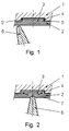
- the housing (1) of the shut-off valve is lined with a sleeve (2) made of elastic, incompressible material in the area of the flowed-through part.
- the cuff (2) has a circumferential collar (3) which is in a circumferential groove (4) comes to lie freely axially. This is achieved in that the width of the collar (3) is less than the width of the groove (4) and an intermediate space (5, 5 ') is created, which is ideally evenly distributed on the two sides.
- the valve disc (6) is shown lifted off the cuff (2) in a slightly open position.
- Fig. 2 the closed shut-off valve is shown.
- the valve disc (6) dips into the sleeve (2) and displaces part of the elastic material of the sleeve (2). If the displaced material has so far evaded on the surface (7) of the sleeve in the form of warps, the material can now escape into the spaces (5, 5 '). This is indicated by the arrows, which also indicate that the evasive movement of the cuff is blocked under one-sided pressure, since the cuff is supported in the groove and thus limits the freedom of movement.
Landscapes
- Engineering & Computer Science (AREA)
- General Engineering & Computer Science (AREA)
- Mechanical Engineering (AREA)
- Lift Valve (AREA)
- Rotary Pumps (AREA)
Description
- Eine Absperrklappe mit elastischer Manschette zum Absperren des Durchflusses in einem Leitungssystem ist ein in der Technik gut bekanntes Produkt. Oft wird ein Modell in einer Vielzahl von Nennweiten und in großer Stückzahl produziert.
- Der Benutzer erwartet von einer solchen Absperrklappe ein sicheres Absperren des Durchflusses eines Fördermediums durch hohe Dichtheit und geringe Leckrate an der Klappenscheibe sowie eine absolute Dichtheit des Innenraumes gegen die Umwelt, sowohl an den Anschlußflanschen als auch am Durchgang der Klappenachse zur Betätigung der Absperrklappe.
- Die in großer Stückzahl verwendeten Absperrklappen sind in der Regel robust, einfach herzustellen und wirtschaftlich kostengünstig und zeichnen sich durch eine sehr einfache Gestaltung der Manschette aus, welche eben und achsensymmetrisch ist und lediglich zwei zylindrische Öffnungen zum Durchlaß der Klappenachse aufweist.
- Zum ersten hat diese Bauform den Nachteil, daß sich die Manschette beim Eintauchen der Klappenscheibe axial verschiebt und keine vorhersehbare Geometrie an der Dichtstelle mehr vorliegt. Die einfache Bauform hat zum zweiten den Nachteil, daß mit der Zeit das elastische Material der Manschette in abgesperrter Stellung der Armatur von der hochdruckbeaufschlagten Seite auf die niederdruckbeaufschlagte Seite der Klappenscheibe ausweicht. Durch dieses axiale Ausweichen wird der Anpreßdruck der Klappenscheibe in die Manschette teilweise abgebaut und die Dichtwirkung verringert.
- Zur Verhinderung des axialen Ausweichens der Manschette sind verschiedene Lösungswege eingeschlagen worden. So ist es allgemein bekannt und in einer Vielzahl von Industriekatalogen dargestellt, die Manschette mit einem umlaufenden Bund zu versehen, welcher von einer Nut im Gehäuse aufgenommen wird. Dieser Bund befindet sich am äußeren Umfang der Manschette und erstreckt sich in axialer Richtung sowohl in die hochdruckseitige als auch in die niederdruckseitige Richtung. Bund und Nut stellen durch ihre geometrischen Abmessungen eine formschlüssige Verbindung der Manschette mit dem Gehäuse dar und verhindern somit beim Eintauchen der Klappenscheibe in die Manschette eine axiale Verschiebung der Manschette. Eine bekannte, in der EP-PS 0 182 676 offenbarte Ausführung zeigt des weiteren eine Manschette mit zwei schmalen, umlaufenden Bunden, welche in Nuten des Gehäuses eingreifen und eine formschlüssige Verankerung bilden.
- Eine den Merkmalen des Oberbegriffes des Anspruchs 1 entsprechende Absperrklappe mit einer Dichtmanschette und einem Bund, der in einer Nut des Gehäuses aufgenommen wird, ist aus der FR-A- 2 069 639 bekannt. Damit das elastische Material der Manschette bei Kontakt mit der Ventilklappe ausweichen kann, ist das Volumen der Nut größer als das des Bundes. Die Nut ist dabei so bemessen, daß ein Ausweichraum zwischen dem Bund und dem Nutgrund vorgesehen ist. Das elastische Material kann somit in radialer Richtung ausweichen, während der Bund in der Nut seitlich ohne Spiel geführt ist.
- Das Problem besteht darin, daß zwar mit den oben genannten Gestaltungsmöglichkeiten ein axiales Verschieben beim Eintauchen der Klappenscheibe verhindert, dem Ausweichen des elastischen Materials der Manschette bei einseitiger Druckbeaufschlagung im Laufe der Zeit aber nicht zufriedenstellend entgegengewirkt wird.
- Der Erfindung liegt die Aufgabe zugrunde, eine Absperrklappe mit elastischer Manschette zu schaffen, bei welcher das axiale Ausweichen der Manschette um die Klappenscheibe verringert ist und die Manschette im Gehäuse verankert ist.
- Das Problem wird durch die im Anspruch 1 angegebene Lehre gelöst. Die mit der Erfindung erzielbaren Vorteile liegen insbesondere darin, daß die Verbesserung der Dichtheit durch einfach einsetzbare konstruktive Abänderungen des Grundtyps erreicht wird. Die verringerte Breite des Bundes der Manschette gegenüber der Breite der im Gehäuse vorhandenen Nut ermöglicht dem elastischen, inkompressiblen Material der Manschette ein zumindest teilweises Ausweichen beim Eintauchen der Klappenscheibe in die Manschette beim Schließen der Klappe. Das Walken der Manschette wird verringert, da für das vom eintauchenden Klappenkörper verdrängte Volumen ein Ausgleichsraum zur Verfügung steht. Die Verformung der Manschette auf der Niederdruckseite ist durch diesen Volumenausgleich überraschenderweise geringer und damit die Dichtwirkung über längere Zeit hinweg gesichert.
- Vorteilhafte Ausgestaltungen der Erfindung sind in den Ansprüchen 2 bis 5 angegeben. Die Weiterbildung nach Anspruch 2 erzeugt eine Vorspannung in der in das Gehäuse eingebrachten Manschette, welche diese in ihren Sitz drückt und eine sich gegen eine axiale Verschiebung widersetzende Reibungskraft erzeugt. Damit wird die elastische Manschette wirksamer als bei dem Grundtyp durch Kraftschluß im Gehäuse festgehalten. Die eingebrachte Vorspannung erschwert außerdem das Ausweichen der Manschette in den Niederdruckbereich bei Beaufschlagung mit dem Fördermedium, da sie der Verformung einen höheren Widerstand entgegensetzt als eine nicht vorgespannte Manschette. Zusätzlich wird die Verankerung der Manschette auch bei geöffneter, nicht eingetauchter Klappenscheibe gewährleistet.
- Die Weiterbildung nach Anspruch 3 offenbart einen günstigen Bereich der Längenverhältnisse, in welchem sich für die Montage, den Betrieb, den Abrieb und die Betätigungskräfte, die Dichtheit und die Verankerung der Manschette besonders gute Ergebnisse erzielen lassen.
- Die Weiterbildung nach Anspruch 4 erschwert zusätzlich das axiale Ausweichen der Manschette bei der einseitigen Beaufschlagung mit dem Druck des Fördermediums, wie es in geschlossener Stellung vorkommt. Mit dem Eintauchen der Klappenscheibe wird der zur Verfügung stehende Raum vollständig ausgefüllt. Das verdrängte Material stützt sich an den Seitenwänden der Nut ab und stellt sich einer weiteren Verformung entgegen.
- Die Weiterbildung nach Anspruch 5 erhöht die Dichtwirkung im Bereich der Klappenachse. Da an dieser besonders kritischen Stelle zwei Dichtfunktionen vorliegen, nämlich das Absperren des Fördermediums vor und hinter der Klappenscheibe und das Abdichten der Armatur gegen die Umwelt, ermöglicht die Verbreiterung des Bundes in diesem Bereich bis zur spielfreien Anlage an die Seitenwände der Nut eine Abstützung der Manschette und wirkt dem Ausweichen der Manschette an der Klappenachse unter Druckbeaufschlagung entgegen. Der Eintauchvorgang im Bereich der Klappenachse ist durch den ständigen Kontakt der Klappenscheibe mit der Manschette verringert und der Volumenausgleich weniger entscheidend.
- Ausführungsbeispiele der Erfindung sind in den Zeichnungen dargestellt und werden im folgenden näher beschrieben. Es zeigen
- Fig. 1
- die Manschette vor dem Eintauchen der Klappenscheibe als Ausschnitt im Längsschnitt, die
- Fig. 2
- die verformte Manschette nach dem Eintauchen der Klappenscheibe als Ausschnitt im Längsschnitt.
- Das Gehäuse (1) der Absperrarmatur ist im Bereich des durchströmten Teils mit einer Manschette (2) aus elastischem, inkompressiblem Material ausgekleidet. Die Manschette (2) weist einen umlaufenden Bund (3) auf, welcher in einer umlaufenden Nut (4) frei axial verschiebbar zu liegen kommt. Bewirkt wird dies dadurch, daß die Breite des Bundes (3) geringer als die Breite der Nut (4) ist und ein Zwischenraum (5, 5') entsteht, welcher im Idealfall gleichmäßig auf die beiden Seiten verteilt ist. Die Klappenscheibe (6) ist in leicht geöffneter Stellung von der Manschette (2) abgehoben dargestellt.
- In Fig. 2 wird die geschlossene Absperrarmatur gezeigt. Die Klappenscheibe (6) taucht in die Manschette (2) ein und verdrängt ein Teil des elastischen Materials der Manschette (2). Wich das verdrängte Material bislang an der Oberfläche (7) der Manschette in Form von Verwerfungen aus, so kann nun das Material in die Zwischenräume (5, 5') ausweichen. Dies wird durch die Pfeile angedeutet, welche auch zusätzlich darauf hinweisen, daß die Ausweichbewegung der Manschette unter einseitiger Druckbeaufschlagung blockiert wird, da die Manschette in der Nut abgestützt wird und somit die Bewegungsfreiheit beschränkt.
Claims (5)
- Absperrklappe, bestehend aus einem Gehäuse (1), einer drehbaren Klappenscheibe (6) und einer elastischen Manschette (2) zur Abdichtung der Klappenscheibe (6) gegen das Gehäuse (1) zwecks Absperren des Durchflusses sowie zur Abdichtung einer von der Klappenscheibe (6) durch eine Durchgangsöffnung in der Manschette (2) in einen Schaft des Gehäuses (1) ragenden Klappenachse gegen das Gehäuse (1), wobei die Manschette (2) mit einem radial außenliegenden, sich über einen Teilbereich der Manschette (2) in axialer Richtung erstreckenden und der in die Manschette (2) eingetauchten Klappenscheibe (6) gegenüberliegenden Bund (3) versehen ist und das Gehäuse (1) eine umlaufende Nut (4) zur Aufnahme des Bundes (3) der Manschette (2) aufweist, dadurch gekennzeichnet, daß der Bund (3) in geöffneter Stellung der Klappenscheibe (6) eine derart verringerte axiale Breite gegenüber der Nut (4) besitzt, daß mindestens ein seitlicher Zwischenraum (5, 5') gebildet wird, in welchen das Material der Manschette (2) beim Eintauchen der Klappenscheibe (6) in die Manschette (2) während des Schließvorganges zumindest teilweise ausweicht.
- Absperrklappe nach Anspruch 1, dadurch gekennzeichnet, daß die elastische Manschette an einem Sitz des Gehäuses (1) anliegt und daß die abgewickelte Länge der elastischen Manschette (2) größer als die abgewickelte Länge ihres Sitzes im Gehäuse (1) ist.
- Absperrklappe nach Anspruch 2, dadurch gekennzeichnet, daß die abgewickelte Länge der elastischen Manschette (2) um 0,5 - 1,5 % größer als die abgewickelte Länge ihres Sitzes im Gehäuse (1) ist.
- Absperrklappe nach einem der Ansprüche 1 bis 3, dadurch gekennzeichnet, daß das von der eingetauchten Klappenscheibe verdrängte Volumen des Materials der Manschette (2) gleich dem in Offenstellung der Klappenscheibe (6) vorhandenen Volumen des Zwischenraums (5,5') ist.
- Absperrklappe nach einem der Ansprüche 1 bis 4, dadurch gekennzeichnet, daß der Bund (3) im Bereich der Durchgangsöffnung der Klappenachse spielfrei an Seitenwänden der Nut (4) des Gehäuses (1) anliegt und nur im übrigen Bereich eine geringere Breite als die Nut (4) besitzt.
Applications Claiming Priority (3)
| Application Number | Priority Date | Filing Date | Title |
|---|---|---|---|
| DE4213521 | 1992-04-24 | ||
| DE4213521A DE4213521A1 (de) | 1992-04-24 | 1992-04-24 | Manschettenverankerung |
| PCT/EP1993/000945 WO1993022588A1 (de) | 1992-04-24 | 1993-04-20 | Manschettenverankerung |
Publications (2)
| Publication Number | Publication Date |
|---|---|
| EP0637365A1 EP0637365A1 (de) | 1995-02-08 |
| EP0637365B1 true EP0637365B1 (de) | 1995-10-25 |
Family
ID=6457408
Family Applications (1)
| Application Number | Title | Priority Date | Filing Date |
|---|---|---|---|
| EP93909374A Expired - Lifetime EP0637365B1 (de) | 1992-04-24 | 1993-04-20 | Absperrklappe mit einer verankerten abdichtungsmanschette |
Country Status (6)
| Country | Link |
|---|---|
| EP (1) | EP0637365B1 (de) |
| JP (1) | JP2597302B2 (de) |
| AT (1) | ATE129548T1 (de) |
| DE (2) | DE4213521A1 (de) |
| ES (1) | ES2080619T3 (de) |
| WO (1) | WO1993022588A1 (de) |
Families Citing this family (5)
| Publication number | Priority date | Publication date | Assignee | Title |
|---|---|---|---|---|
| DE69720617T2 (de) * | 1996-07-31 | 2004-01-22 | Ksb S.A.S. | Zentrische Absperrklappe mit langer Lebensdauer |
| DE102005002876A1 (de) * | 2005-01-21 | 2006-08-17 | Groupinox Gmbh | Absperrvorrichtung |
| FR2978996B1 (fr) | 2011-08-12 | 2014-05-30 | Ksb Sas | Bague d'etancheite en trois parties |
| FR2984446B1 (fr) | 2011-12-14 | 2014-06-13 | Ksb Sas | Robinet a papillon |
| FR2987094B1 (fr) | 2012-02-21 | 2016-08-05 | Ksb Sas | Robinet a papillon |
Family Cites Families (14)
| Publication number | Priority date | Publication date | Assignee | Title |
|---|---|---|---|---|
| US3095177A (en) * | 1961-03-10 | 1963-06-25 | Frank G Muller | Valve assembly and seal forming means for the same |
| US3173650A (en) * | 1962-03-05 | 1965-03-16 | Crane Co | Butterfly valve seat construction |
| DE1750961C3 (de) * | 1967-06-22 | 1974-12-05 | Garlock Inc., Palmyra, N.Y. @(V.St.A.) | Drosselklappe |
| GB1253430A (en) * | 1969-07-14 | 1971-11-10 | Saunders Valve Co Ltd | Improvements in butterfly valve |
| US3633872A (en) * | 1969-11-24 | 1972-01-11 | Fmc Corp | Butterfly valve |
| DE2006186A1 (de) * | 1970-02-11 | 1971-08-19 | Huebner Vamag | Verfahren zum Einsetzen eines Sitz ringes fur den Absperrkorper einer Armatur |
| US3647180A (en) * | 1970-04-06 | 1972-03-07 | Teledyne Mid America Corp | Butterfly valve construction |
| US3661171A (en) * | 1970-05-12 | 1972-05-09 | Xomox Corp | Butterfly valve |
| US3782684A (en) * | 1971-09-20 | 1974-01-01 | Rockwell International Corp | Seat insert for butterfly-type valves |
| FR2260041B1 (de) * | 1974-02-06 | 1976-10-08 | Amri | |
| JPS55126060U (de) * | 1979-03-01 | 1980-09-06 | ||
| FR2570789B1 (fr) * | 1984-09-27 | 1986-12-05 | Amri | Robinet a papillon a caractere universel et procede de fabrication dudit robinet |
| SU1525392A1 (ru) * | 1988-01-12 | 1989-11-30 | Всесоюзный Научно-Исследовательский Институт Винограда И Продуктов Его Переработки "Магарач" | Дисковый затвор |
| JPH02275183A (ja) * | 1989-04-14 | 1990-11-09 | Murata Mach Ltd | シートリング挿入方法 |
-
1992
- 1992-04-24 DE DE4213521A patent/DE4213521A1/de not_active Withdrawn
-
1993
- 1993-04-20 WO PCT/EP1993/000945 patent/WO1993022588A1/de not_active Ceased
- 1993-04-20 JP JP5518876A patent/JP2597302B2/ja not_active Expired - Lifetime
- 1993-04-20 ES ES93909374T patent/ES2080619T3/es not_active Expired - Lifetime
- 1993-04-20 DE DE59300830T patent/DE59300830D1/de not_active Expired - Lifetime
- 1993-04-20 AT AT93909374T patent/ATE129548T1/de not_active IP Right Cessation
- 1993-04-20 EP EP93909374A patent/EP0637365B1/de not_active Expired - Lifetime
Also Published As
| Publication number | Publication date |
|---|---|
| DE4213521A1 (de) | 1993-10-28 |
| EP0637365A1 (de) | 1995-02-08 |
| WO1993022588A1 (de) | 1993-11-11 |
| JPH07501607A (ja) | 1995-02-16 |
| ATE129548T1 (de) | 1995-11-15 |
| JP2597302B2 (ja) | 1997-04-02 |
| ES2080619T3 (es) | 1996-02-01 |
| DE59300830D1 (de) | 1995-11-30 |
Similar Documents
| Publication | Publication Date | Title |
|---|---|---|
| DE1600811C3 (de) | Zu- und abfluflseitige Dichtringanordnung für einen Kugelhahn | |
| DE2916984A1 (de) | Sitz fuer ein absperrelement eines absperrorgans und absperrorgan mit einem solchen sitz | |
| DE3114197A1 (de) | "ventil mit einer feuerbestaendigen dichtung" | |
| DE3712489C2 (de) | Sitzanordnung für einen Kugelhahn | |
| EP0067403A1 (de) | Hahn mit Kugelküken | |
| DE2822982A1 (de) | Drehkegelventil | |
| EP0637364B1 (de) | Klappenachsenabdichtung | |
| DE3831554A1 (de) | Drosselrueckschlagventil | |
| EP0604704A1 (de) | Kugelventil mit Dichtungsmitteln für das Verschlussteil | |
| EP0478100A2 (de) | Absperrvorrichtung für eine Gasleitung | |
| DE2846631C2 (de) | Dichtring | |
| EP3271623B1 (de) | Hubventil mit drehentkopplungseinrichtung | |
| DE102023117369A1 (de) | Kugelventil einer Kältemittelventileinrichtung für eine Klimaanlage | |
| WO1993022588A1 (de) | Manschettenverankerung | |
| EP0105365B1 (de) | Absperr- bzw. regelarmatur | |
| DE19704847A1 (de) | Ventil | |
| EP1257753B1 (de) | Dichtungsanordnung | |
| DE9218556U1 (de) | Manschettenverankerung | |
| DE19522081C1 (de) | Kugelhahn | |
| DE102010055430B4 (de) | Klappenventil sowie Dichtung für ein Klappenventil | |
| AT381151B (de) | Druckbeaufschlagter ventilsitz | |
| EP0224825A2 (de) | Hydraulische Blockierfeder | |
| DE69407401T2 (de) | Ventil | |
| EP0318737A2 (de) | Kugelhahn | |
| DE202016104214U1 (de) | Käfigventil |
Legal Events
| Date | Code | Title | Description |
|---|---|---|---|
| PUAI | Public reference made under article 153(3) epc to a published international application that has entered the european phase |
Free format text: ORIGINAL CODE: 0009012 |
|
| 17P | Request for examination filed |
Effective date: 19940817 |
|
| AK | Designated contracting states |
Kind code of ref document: A1 Designated state(s): AT BE CH DE DK ES FR GB IT LI LU NL SE |
|
| 17Q | First examination report despatched |
Effective date: 19950320 |
|
| GRAA | (expected) grant |
Free format text: ORIGINAL CODE: 0009210 |
|
| AK | Designated contracting states |
Kind code of ref document: B1 Designated state(s): AT BE CH DE DK ES FR GB IT LI LU NL SE |
|
| PG25 | Lapsed in a contracting state [announced via postgrant information from national office to epo] |
Ref country code: DK Effective date: 19951025 |
|
| REF | Corresponds to: |
Ref document number: 129548 Country of ref document: AT Date of ref document: 19951115 Kind code of ref document: T |
|
| REF | Corresponds to: |
Ref document number: 59300830 Country of ref document: DE Date of ref document: 19951130 |
|
| ITF | It: translation for a ep patent filed | ||
| PG25 | Lapsed in a contracting state [announced via postgrant information from national office to epo] |
Ref country code: SE Effective date: 19960125 |
|
| REG | Reference to a national code |
Ref country code: ES Ref legal event code: FG2A Ref document number: 2080619 Country of ref document: ES Kind code of ref document: T3 |
|
| GBT | Gb: translation of ep patent filed (gb section 77(6)(a)/1977) |
Effective date: 19960106 |
|
| ET | Fr: translation filed | ||
| PG25 | Lapsed in a contracting state [announced via postgrant information from national office to epo] |
Ref country code: AT Effective date: 19960420 |
|
| PG25 | Lapsed in a contracting state [announced via postgrant information from national office to epo] |
Ref country code: LU Free format text: LAPSE BECAUSE OF NON-PAYMENT OF DUE FEES Effective date: 19960430 |
|
| PLBE | No opposition filed within time limit |
Free format text: ORIGINAL CODE: 0009261 |
|
| STAA | Information on the status of an ep patent application or granted ep patent |
Free format text: STATUS: NO OPPOSITION FILED WITHIN TIME LIMIT |
|
| 26N | No opposition filed | ||
| REG | Reference to a national code |
Ref country code: GB Ref legal event code: IF02 |
|
| PGFP | Annual fee paid to national office [announced via postgrant information from national office to epo] |
Ref country code: CH Payment date: 20120426 Year of fee payment: 20 Ref country code: BE Payment date: 20120430 Year of fee payment: 20 Ref country code: NL Payment date: 20120514 Year of fee payment: 20 Ref country code: DE Payment date: 20120425 Year of fee payment: 20 |
|
| PGFP | Annual fee paid to national office [announced via postgrant information from national office to epo] |
Ref country code: FR Payment date: 20120510 Year of fee payment: 20 Ref country code: GB Payment date: 20120425 Year of fee payment: 20 |
|
| PGFP | Annual fee paid to national office [announced via postgrant information from national office to epo] |
Ref country code: IT Payment date: 20120423 Year of fee payment: 20 |
|
| PGFP | Annual fee paid to national office [announced via postgrant information from national office to epo] |
Ref country code: ES Payment date: 20120420 Year of fee payment: 20 |
|
| REG | Reference to a national code |
Ref country code: DE Ref legal event code: R071 Ref document number: 59300830 Country of ref document: DE |
|
| REG | Reference to a national code |
Ref country code: DE Ref legal event code: R071 Ref document number: 59300830 Country of ref document: DE |
|
| BE20 | Be: patent expired |
Owner name: *KSB A.G. Effective date: 20130420 |
|
| REG | Reference to a national code |
Ref country code: CH Ref legal event code: PL |
|
| REG | Reference to a national code |
Ref country code: NL Ref legal event code: V4 Effective date: 20130420 |
|
| REG | Reference to a national code |
Ref country code: GB Ref legal event code: PE20 Expiry date: 20130419 |
|
| REG | Reference to a national code |
Ref country code: ES Ref legal event code: FD2A Effective date: 20130712 |
|
| PG25 | Lapsed in a contracting state [announced via postgrant information from national office to epo] |
Ref country code: ES Free format text: LAPSE BECAUSE OF EXPIRATION OF PROTECTION Effective date: 20130421 Ref country code: GB Free format text: LAPSE BECAUSE OF EXPIRATION OF PROTECTION Effective date: 20130419 Ref country code: DE Free format text: LAPSE BECAUSE OF EXPIRATION OF PROTECTION Effective date: 20130423 |