EP0637191A2 - Appareil de traitement d'un signal d'effet spatial - Google Patents
Appareil de traitement d'un signal d'effet spatial Download PDFInfo
- Publication number
- EP0637191A2 EP0637191A2 EP94305664A EP94305664A EP0637191A2 EP 0637191 A2 EP0637191 A2 EP 0637191A2 EP 94305664 A EP94305664 A EP 94305664A EP 94305664 A EP94305664 A EP 94305664A EP 0637191 A2 EP0637191 A2 EP 0637191A2
- Authority
- EP
- European Patent Office
- Prior art keywords
- signal
- transfer characteristics
- listener
- signals
- speakers
- Prior art date
- Legal status (The legal status is an assumption and is not a legal conclusion. Google has not performed a legal analysis and makes no representation as to the accuracy of the status listed.)
- Granted
Links
Images


Classifications
-
- H—ELECTRICITY
- H04—ELECTRIC COMMUNICATION TECHNIQUE
- H04S—STEREOPHONIC SYSTEMS
- H04S1/00—Two-channel systems
- H04S1/002—Non-adaptive circuits, e.g. manually adjustable or static, for enhancing the sound image or the spatial distribution
-
- H—ELECTRICITY
- H04—ELECTRIC COMMUNICATION TECHNIQUE
- H04R—LOUDSPEAKERS, MICROPHONES, GRAMOPHONE PICK-UPS OR LIKE ACOUSTIC ELECTROMECHANICAL TRANSDUCERS; DEAF-AID SETS; PUBLIC ADDRESS SYSTEMS
- H04R2205/00—Details of stereophonic arrangements covered by H04R5/00 but not provided for in any of its subgroups
- H04R2205/022—Plurality of transducers corresponding to a plurality of sound channels in each earpiece of headphones or in a single enclosure
-
- H—ELECTRICITY
- H04—ELECTRIC COMMUNICATION TECHNIQUE
- H04R—LOUDSPEAKERS, MICROPHONES, GRAMOPHONE PICK-UPS OR LIKE ACOUSTIC ELECTROMECHANICAL TRANSDUCERS; DEAF-AID SETS; PUBLIC ADDRESS SYSTEMS
- H04R2499/00—Aspects covered by H04R or H04S not otherwise provided for in their subgroups
- H04R2499/10—General applications
- H04R2499/15—Transducers incorporated in visual displaying devices, e.g. televisions, computer displays, laptops
-
- H—ELECTRICITY
- H04—ELECTRIC COMMUNICATION TECHNIQUE
- H04S—STEREOPHONIC SYSTEMS
- H04S1/00—Two-channel systems
- H04S1/002—Non-adaptive circuits, e.g. manually adjustable or static, for enhancing the sound image or the spatial distribution
- H04S1/005—For headphones
-
- H—ELECTRICITY
- H04—ELECTRIC COMMUNICATION TECHNIQUE
- H04S—STEREOPHONIC SYSTEMS
- H04S2400/00—Details of stereophonic systems covered by H04S but not provided for in its groups
- H04S2400/01—Multi-channel, i.e. more than two input channels, sound reproduction with two speakers wherein the multi-channel information is substantially preserved
-
- H—ELECTRICITY
- H04—ELECTRIC COMMUNICATION TECHNIQUE
- H04S—STEREOPHONIC SYSTEMS
- H04S2420/00—Techniques used stereophonic systems covered by H04S but not provided for in its groups
- H04S2420/01—Enhancing the perception of the sound image or of the spatial distribution using head related transfer functions [HRTF's] or equivalents thereof, e.g. interaural time difference [ITD] or interaural level difference [ILD]
Definitions
- the present invention relates generally to sound image localizing apparatus used when sound signals are reproduced through speakers, and more specifically to a surround signal processing apparatus used when surround signals are reproduced in such way as to surround a listener or listeners.
- the sound image implies a virtual sound source image from which a listener feels that a sound is reproduced. Further, the sound image can be localized at any desired position away from a speaker or speakers.
- two front speakers are arranged in front of a listener for stereophonic sound reproduction and at least one or two rear speaker are additionally arranged behind the listener for surround sound reproduction; in other words, at least three speakers must be arranged at the minimum around a listener.
- surround sound is reproduced on the basis of a one-system surround signal or a center channel is additionally required to be reproduced as with the case of the 3-1 system of high vision HDTV (High Definition TV)
- one or two additional center speakers must be arranged. Therefore, amplifiers and cables corresponding to the numbers of the reproduced channels are necessary.
- sound image localization signals obtained by transforming the rear channel signals are reproduced through two front speakers arranged at two predetermined positions in front of a listener, in addition to the original two (L- and R-) channel stereophonic signals.
- two pairs of speakers are arranged in front of a listener; only the original L- and R-channel signals are reproduced through one pair of the speakers; and the sound image localization signals are applied to the other pair of the speakers.
- the sound image localization as described above, even if no rear speakers are arranged behind a listener in practice, it has become possible to reproduce surround sound in such a way that the listener can hear sound as if it came from the rear side of the listener.
- FIG. 2 is a conceptual diagram showing the surround signal processing apparatus based upon the sound image localization technique.
- a surround signal processing apparatus 20 of four channel type receives two channel stereophonic signals L and R, a center channel signal C for improving the localization of the middle position of the stereophonic sound, and a rear channel signal S for obtaining a surround stereophonic sound effect from the outside. Further, the processing apparatus 20 transforms the rear channel signal S and the center channel signal C into spatial localization signals for localizing sound signals at any desired sound image positions, respectively, in order to realize the surround reproduction in such a way that the reproduced sound can surround a listener LM.
- this sound image processing apparatus 20 it is possible to obtain a surround stereophonic sound effect by reproducing the stereophonic signals L and R and the transformed spatial localization signals through two speakers SP1 and SP2 arranged on the front left and right sides of a listener LM, without arranging two rear left and right speakers SP3 and SP4, a front middle speaker SP5, and a rear middle speaker SP6.
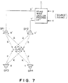
- FIG. 3 is an illustration for assistance in explaining a principle that a sound image can be localized at any given spatial position enclosing a listener LM by use of two stereophonic speakers SP1 and SP2.
- the transfer characteristics (the frequency response to an impulse) between the left side speaker SP1 and both left and right ears of a listener LM are denoted by h1L and h1R; and the transfer characteristics between the right side speaker SP2 and both left and right ears of the listener LM are denoted by h2L and h2R; and the transfer characteristics between a speaker assumed to be arranged at an intended localization position x and both left and right ears of the listener LM are denoted by pLx and pRx, respectively.
- the respective transfer characteristics can be measured by arranging a speaker, a human head (or a dummy head) and two microphones (arranged at both the ear positions thereof). Further, the waveforms of the measured characteristics are processed appropriately.
- a sound source signal X required to be localized is passed through two signal transforming circuits 21A and 21B (whose transfer characteristics can be represented by cfLx and cfRx), respectively and further reproduced through two speakers SP1 and SP2, respectively.
- the signal required to be localized is processed by the signal transforming circuits 21A and 21B (referred to as localization filters for a position x) provided with the transfer characteristics cfLx and cfRx calculated in accordance with the formulae (14a) to (14c) respectively, it is possible to localize a sound image at an objective localization position x.
- a sound image can be localized at an objective position x by processing the surround signal through a pair of localization filters determined by setting a rear speaker arrangement position to a sound image localization position x, and further by reproducing the filtered sound source signal through the two front speakers SP1 and SP2, respectively.
- a surround signal processing apparatus has been so far constructed by combining a plurality of pairs of localization filters, as shown in FIG. 4 or 5, respectively.
- FIG. 4 shows a prior art surround signal processing apparatus which can process the sound image localization in such a way that two rear channel signals SL and SR can be reproduced at two symmetrical rear left and right positions of a listener LM, on the basis of two channel stereophonic signals L and R, a single channel center signal C, and two rear channel surround (rear) signals SL and SR all outputted by a surround decoder SD.
- a pair of the localizing filters 21A and 21B is provided for each of the two rear channel signals SL and SR, and two sound image are localized at two positions of the two rear speakers SP3 and SP4, as shown in FIG. 2. That is, the signals obtained by addition of the signals L, R and C and the sound image localization processed signals are reproduced by a pair of the two front speakers SP1 and SP2, respectively. Therefore, in this processing apparatus, the sound image localization processing is made by use of 4 filters in total for two surround (rear) channel signals SL and SR.
- FIG. 5 shows a prior art surround signal processing apparatus which can cope with a surround reproduction system using a monophonic (single system) rear surround signal.
- this processing apparatus a pair of localization filters (21A and 21B) for one channel are provided, and the surround signal S can be localized at the position of the speaker SP6, as shown in FIG. 2, by use of two filers in total.
- the present invention provides a surround signal processing apparatus for reproducing an inputted rear surround signal, together with two-channel front stereophonic signals, through a pair of transducers arranged in front of and at substantially right-and-left symmetrical positions with respect to a listener, so as to localize sound images of the reproduced rear surround signals at predetermined positions relative to the listener, which comprises: filter means for processing the inputted rear surround signal in accordance with predetermined transfer characteristics provided therein; inverting means for inverting polarity of the signal processed by said filter means to obtain an inversion signal thereof; first adding means for adding the signal processed by said filter means and one of the stereophonic signals, to output the obtained addition signal to one of the pair of the transducers; and second adding means for adding the inversion signal inverted by said inverting means and the other of the stereophonic signals, to output the obtained addition signal to the other of the pair of the transducers; and wherein: the transfer characteristics of said filter means are set as follows: (F -
- the apparatus further comprises: storing means for storing a plurality of transfer characteristics according to a plurality of sound image localization positions, respectively; and setting means for reading the transfer characteristics according to at least one desired sound image localization position from a plurality of stored transfer characteristics and for setting the read transfer characteristics to said filter means.
- the present invention provides a surround signal processing apparatus for reproducing an inputted rear surround signal, together with two-channel front stereophonic signals, through a pair of transducers arranged in front of and at substantially right-and-left symmetrical position with respect to a listener, so as to localize sound images of the reproduced rear surround signals at predetermined positions relative to the listener, which comprises: first signal forming means for forming first and second independent signals on the basis of the inputted rear surround signal; second signal forming means for forming a first addition signal and a first subtraction signal, respectively on the basis of the first and second independent signals; first filter means for processing the first addition signal in accordance with first transfer characteristics P provided therein; second filter means for processing the first subtraction signal in accordance with second transfer characteristics N provided therein; third signal forming means for forming a second addition signal and a second subtraction signal, respectively on the basis of signals processed by said first and second filter means; first adding means for adding the second addition signal and one of the stereophonic signals, to output the obtained addition signal to one
- the present invention provides an audio video reproducing apparatus having a display unit to reproduce picture and a pair of speakers arranged on both sides of the display unit to reproduce audio signals, for reproducing an inputted rear surround signal, together with two-channel front stereophonic signals, through the pair of the speakers, so as to localize sound images of the reproduced rear surround signals at predetermined positions relative to a viewer, which comprises: filter means for processing the inputted rear surround signal in accordance with predetermined transfer characteristics provided therein; inverting means for inverting polarity of the signal processed by said filter means to obtain an inversion signal thereof; first adding means for adding the signal processed by said filter means and one of the stereophonic signals, to output the obtained addition signal to one of the pair of the speakers; and second adding means for adding the inversion signal inverted by said inverting means and the other of the stereophonic signals, to output the obtained addition signal to the other of the pair of the speakers; and wherein: the transfer characteristics of said filter means are set as follows: (F - K) / (S - A), where
- the present invention provides an audio video reproducing apparatus having a display unit to reproduce picture and a pair of speakers arranged on both sides of the display unit to reproduce audio signals, for reproducing an inputted rear surround signal, together with two-channel front stereophonic signals, through the pair of the speakers, so as to localize sound images of the reproduced rear surround signals at predetermined positions relative to a viewer, which comprises: first signal forming means for forming first and second independent signals on the basis of the inputted rear surround signal; second signal forming means for forming a first addition signal and a first subtraction signal, respectively on the basis of the first and second signals; first filter means for processing the first addition signal in accordance with first transfer characteristics P provided therein; second filter means for processing the first subtraction signal in accordance with second transfer characteristics N provided therein; third signal forming means for forming a second addition signal and a second subtraction signal, respectively on the basis of signals processed by said first and second filter means; first adding means for adding the second addition signal and one of the stereophonic signals, to output the obtained addition signal to
- the apparatus further comprises: storing means for storing a plurality of transfer characteristics according to a plurality of sound image localization positions, respectively; and setting means for reading the transfer characteristics according to at least one desired sound image localization position from a plurality of stored transfer characteristics and for setting the read transfer characteristics to said first and second filter means.
- the apparatus further comprises: storing means for storing a plurality of transfer characteristics according to a plurality of sound image localization positions, respectively; and setting means for reading the transfer characteristics according to at least one desired sound image localization position from a plurality of stored transfer characteristics and for setting the read transfer characteristics to said first and second filter means.
- the present invention provides a surround signal processing apparatus for reproducing surround signals through a pair of transducers and for localizing sound images of the surround signals at positions different from those at which the pair of the transducers are arranged, which comprises: first signal forming means for forming a subtraction signal on the basis of inputted two-channel stereophonic signals; filter means for processing the subtraction signal in accordance with predetermined transfer characteristics provided therein; second signal forming means for forming an inversion signal by inverting polarity of the signal processed by said filter means; first adding means for adding the signal processed by said filter means and one of the stereophonic signals and outputting the added signal to one of the pair of the transducers; and second adding means for adding the inversion signal obtained by said second forming means and the other of the stereophonic signals and outputting the added signal to the other of the pair of the transducers; and wherein: the transfer characteristics of said filter means are set as follows: (F - K) / (S - A), where S denotes transfer characteristics between one of the transducers
- the apparatus further comprises: storing means for storing a plurality of transfer characteristics according to a plurality of sound image localization positions, respectively; and setting means for reading the transfer characteristics according to at least one desired sound image localization position from a plurality of stored transfer characteristics and for setting the read transfer characteristics to said filter means.
- the present invention provides an audio video reproducing apparatus having means to reproduce picture and audio signals, a pair of loud speakers to reproduce the audio signal arranged on both sides of a display unit to reproduce the picture signal and a surround signal processor for reproducing an inputted rear surround signal, together with two-channel front stereophonic signals, through the pair of the loud speakers, so as to localize sound images of the reproducing surround signals at positions different from the pair of the loud speakers, which comprises: adjusting means for adjusting relative amplitude characteristics of the two-channel front stereophonic signals and the rear surround signal; first signal forming means for forming a first addition signal and a first subtraction signal on the basis of the adjusted rear surround signals; first filter means for processing the first addition signal in accordance with first transfer characteristics P provided therein; second filter means for processing the first subtraction signal in accordance with second transfer characteristics N provided therein; second signal forming means for forming a second addition signal and a second subtraction signal on the basis of the signals processed by said first and second filter means; first adding means for adding the second addition signal and one
- the apparatus further comprises: storing means for storing a plurality of transfer characteristics according to a plurality of sound image localization positions, respectively; and setting means for reading the transfer characteristics according to at least one desired sound image localization position from a plurality of stored transfer characteristics and for setting the read transfer characteristics to said first and second filter means.
- FIG. 6 shows a first embodiment of the surround signal processing apparatus according to the present invention.
- the processing apparatus is composed of a surround processing circuit (surround decoder) SD, an additional signal processing circuit OP, and a sound image localization processing circuit 1.
- the sound image localization processing circuit 1 is an essential portion of the present invention, which is composed of a first adder 2, a first subtracter 3, a first filter 4, a second filter 5, a second adder 6, a second subtracter 7 and two amplitude adjusters 12.
- the surround processing circuit SD is a well-known decoder for demodulating signals inputted thereto to generate the front stereophonic signals L and R, the center signal C, and the rear stereophonic signals SL and SR.
- the additional signal processing circuit OP includes circuits for processing these signals L, R, C, SL and SR generated by the surround processing circuit SD, for amplitude adjustment, reverberation processing, reflected sound addition, etc., which are incorporated as occasion demands.
- Information related to these amplitude adjustment, reverberation processing, reflected sound addition, etc. is stored in a memory 14 and is applied to the additional signal processing circuit OP via CPU 15 to conduct a specific processing.
- the gain characteristics (relative amplitude characteristics) of the amplitude adjuster 12 is also stored in the memory 14 and applied to the adjusters 12 via CPU 15.
- first filter 4 and the second filter 5 are both convolution calculating means (e.g., digital signal processor) such as convolvers provided with P and N transfer characteristics (to be described later in further detail), respectively.
- convolution calculating means e.g., digital signal processor
- the rear stereophonic signals SL and SR applied by the surround processing circuit SD and the additional signal processing circuit OP are inputted to the sound image localization processing circuit 1.
- a first addition signal (SL + SR) of both and a first subtraction signal (SL -SR) between both are generated by the first adder 2 and the first subtracter 3, respectively.
- the generated first addition signal is processed by the first filer 4, and the generated first subtraction signal is processed by the second filter 5.
- a second addition signal (P + N) of both and a second subtraction signal (P - N) between both are generated by the second adder 6 and the second subtracter 7 as processed output signals Y' and X', respectively.
- the processed output signals Y' and X' are inputted to the amplitude adjusters 12, respectively, in which amplitude of the processed output signals Y' and x' are adjusted with respect to the front stereophonic signals L and R and the center signal C.
- a third adder 8 adds the adjusted processed output signal X', the front stereophonic signal L and the center signal C.
- a fourth adder 9 adds the adjusted processed output signal Y', the front stereophonic signal R and the center signal C.
- a pair of the added stereophonic signals as described above are reproduced through a pair of transducers (a pair of loud speakers SP1 and SP2, in this embodiment), so that a listener LM can hear the reproduced sound.
- the two loud speakers SP1 and SP2 are arranged in front of the listener LM at two symmetrical positions with respect to him or her.
- S denotes the transfer characteristics between each of a pair of the loud speakers SP1 and SP2 and each listener's (LM) ear positioned on the same side as each speaker;
- A denotes the transfer characteristics between each of a pair of the loud speakers SP1 and SP2 and each listener's ear positioned on the opposite side to each speaker;
- F denotes the transfer characteristics between each of a pair of positions at which the sound images of surround signals are required to be localized (a pair of positions at which two virtual rear loud speakers SP3 and SP4 are arranged in symmetry with respect to the listener LM) and each listener's ear positioned on the same side as each position;
- K denotes the transfer characteristics between each of a pair of positions at which the sound images of surround signals are required to be localized and each listener's ear positioned on the opposite side to each position.
- the operator [+] designates an addition calculation of the two transfer characteristics; the operator [-] designates a subtraction of the two transfer characteristics; and the operator [/] designates a reverse convolution calculation, respectively.
- the same side indicates that the ear (e.g., the right side ear) and the speaker (e.g., the right side speaker) are positioned on the same side, and the opposite side indicates that the ear (e.g., the right side ear) and the speaker (e.g., the left side speaker) are positioned on the opposite side to each other.
- these transfer characteristics can be obtained as follows: actual speakers are arranged at predetermined rear positions in a no-sound space; two microphones are arranged at both ear positions of a human head (or a dummy head); the sound signals reproduced by the speakers are measured by the microphones; and the waveforms of the obtained measurement data are further processed appropriately.
- FIG. 8 is a flowchart for illustrating steps of this method.
- FIG. 9 shows a block diagram of a HRTF measuring system.
- a pair of microphones ML and MR are set at the positions of the ears of a human head (or a dummy head) DM. From a speaker SP these microphones receive sounds to be measured. Further, a source sound sw(t) (namely, reference data) and the sounds l(t) and r(t) to be measured (namely, data to be measured) L and R are recorded by recorders DAT in synchronization with one another.
- impulse sounds and noises such as a white noise may be used as the source sound sw(t).
- a white noise is preferable for improving the signal-to-noise ratio (S/N) because of the facts that the white noise is a continuous sound and that the energy distribution of the white noise is constant over what is called an audio frequency band.
- the speaker SP is placed at a position (hereunder sometimes referred to as a measurement position) corresponding to a plurality of central angles ⁇ (incidentally, the position of the human head (or dummy head) DM is the center and the central angle corresponding to the just front of the human head is set to be 0 degree). Furthermore, the sounds radiated from these speakers are recorded continuously for a predetermined duration. Thus, basic data on the head related transfer characteristics are collected and measured.
- the source sound sw(t) and the sounds l(t) and r(t) to be measured recorded in step 101 in synchronization with one another are processed by a workstation (not shown).
- Sw( ⁇ ), Y( ⁇ ) and IR( ⁇ ) denote the source sound in frequency-domain representation (namely, the reference data), the sound to be measured, which is in frequency-domain representation, (namely, the data to be measured) and the head-related transfer characteristics in frequency-domain representation obtained at the measurement positions, respectively.
- Y( ⁇ ) IR( ⁇ ) ⁇ Sw( ⁇ )
- IR( ⁇ ) Y( ⁇ )/Sw( ⁇ )
- the reference data sw(t) and the measured data l(t) and r(t) obtained in step 101 are extracted as the reference data Sw( ⁇ ) and the measured data Y( ⁇ ) by using synchronized windows and performing FFT thereon to expand the extracted data into finite Fourier series with respect to discrete frequencies.
- the head related transfer characteristics IR( ⁇ ) composed of a pair of left and right transfer characteristics corresponding to each sound image location are calculated and estimated from the equation (16).
- the head related transfer characteristics respectively corresponding to 12 positions set every 30 degrees are obtained.
- the head related transfer characteristics composed of a pair of left and right transfer characteristics will be referred to simply as head related transfer characteristics (namely, an impulse response). Further, the left and right transfer characteristics will not be referred to individually.
- the head related transfer characteristics in time-domain representation will be denoted by ir(t) and those in frequency-domain representation will be denoted by IR( ⁇ ).
- time-base response (namely, the impulse response) ir(t) (namely, a first impulse response) is obtained by performing an inverse FFT on the computed frequency responses IR( ⁇ ).
- the impulse response ir(t) obtained in step 102 is shaped.
- the first impulse response ir(t) obtained in step 102 is expanded with respect to discrete frequencies by performing FFT over what is called an audio spectrum.
- the frequency response IR( ⁇ ) is obtained.
- components of an unnecessary band for instance, large dips may occur in a high frequency band but such a band are unnecessary for the sound image localization
- BPF band-pass filter
- Hz hertz
- kHz kilo-hertz
- a window processing is performed on ir(t) (namely, the impulse response) on the time base or axis by using an extraction window (for instance, a window represented by a cosine function).
- an extraction window for instance, a window represented by a cosine function.
- a second impulse response ir(t) is obtained.
- the FFT transform and the inverse FFT transform to be performed before the generation of the first impulse response ir(t) is effected may be omitted.
- the first impulse response ir(t) can be utilized for monitoring and can be reserved as the proto-type of the coefficients.
- the effects of the BPF can be confirmed on the time axis by comparing the first impulse response ir(t) with the second impulse response ir(t).
- the first impulse response ir(t) can be preserved as basic transfer characteristics to be used for obtaining the head related transfer characteristics at the intermediate position by computation instead of actual observation.
- cfLx(t) ⁇ h2R(t)*pLx(t) - h2L(t)*pRx(t) ⁇ *g(t)
- cfRx(t) ⁇ -h1R(t)*pLx(t) + h1L(t)*pRx(t) ⁇ *g(t)
- the function g(t) of time t is an inverse Fourier transform of G( ⁇ ) which is a kind of an inverse filter of the term ⁇ H1L( ⁇ ) ⁇ H2R( ⁇ ) - H2L( ⁇ ) ⁇ H1R( ⁇ ) ⁇ .
- This time-dependent function g(t) can be relatively easily obtained from the head-related transfer characteristics h1L(t), h1R(t), h2L(t) and h2R(t) by using a method of least squares. This respect is described in detail in, for instance, the article entitled "Inverse filter design program based on least square criterion", Journal of Acoustical Society of Japan, 43[4], pp. 267 to 276, 1987.
- the time-dependent function g(t) obtained by using the method of least squares as above described is substituted for the equations (14a') and (14b'). Then, the pair of the transfer characteristics cfLx(t) and cfRx(t) for localizing a sound image at each sound image location are obtained not adaptively but uniquely as a time-base or time-domain impulse response by performing the convolution operations according to the equations (14a') and (14b'). Furthermore, the coefficients (namely, the sequence of the coefficients) are used as the coefficient data.
- the transfer characteristics cfLx(t) and cfRx(t) of an entire sapce are obtained correspondingly to the target sound image locations or positions established every 30 degrees over a wide space (namely, the entire space), the corresponding azimuth angles of which are within the range from the very front of the human head to 90 degrees clockwise and anticlockwise (incidentally, the desired location of the sound image is included in such a range) and may be beyond such a range.
- the characters cfLx(t) and cfRx(t) designate the transfer characteristics (namely, the impulse response) of the localization filters, as well as the coefficients (namely, the sequence of the coefficients).
- various processing for instance, a window processing and a shaping processing is effected in steps 101 to 103, as described above, to "shorten” the head-related transfer characteristics (namely, the impulse response) ir(t) to be substituted for h1L(t), ..., and h2R(t).
- the transfer characteristics (namely, the coefficients) of the localization filters may be obtained by performing FFT on the transfer characteristics (namely, the coefficients) cfLx(t) and cfRx(t) calculated as described above to find the frequency response, and then performing a moving average processing on the frequency response using a constant predetermined shifting width and finally effecting an inverse FFT of the result of the moving averzage processing.
- the unnecessary peaks and dips can be removed as the result of the moving average processing.
- the convergence of the time response to be realized can be quickened and the size of the localization filter can be reduced.
- One of the spectral distributions of the source sounds of the sound source, on which the sound image localization processing is actually effected by using the convolvers is like that of a pink noise.
- the intensity level gradually decreases in a high (namely, long) length region.
- the source sound of the sound source is different from single tone. Therefore, when the convolution operation (or integration) is effected, an overflow may occur. As a result, a distortion in signal may occur.
- the coefficient having a maximum gain is first detected among the coefficients cfLx(t) and cfRx(t) of the localization filters. Then, the scaling of all of the coefficients is effected in such a manner that no overflow occurs when the convolution of the coefficient having the maximum gain and a white noise of 0 dB is performed.
- the sum of squares of each set of the coefficients cfLx(t) and cfRx(t) of the localization filters is first obtained. Then, the localization filter having a maximum sum of the squares of each set of the coefficients thereof is found. Further, the scaling of the coefficients is performed such that no overflow occurs in the found localization filter having the maximum sum. Incidentally, the same scaling ratio is used for the scaling of the coefficients of all of the localization filters in order not to lose the balance of the localization filters corresponding to sound image locations, respectively.
- coefficient data namely, data on the groups of the coefficients of the impulse response
- the localization filters namely, convolvers to be described later
- the coefficients namely, the sequence of the coefficients
- 12 sets or groups of the coefficients cfLx(t) and cfRx(t) by which the sound image can be localized at the positions set at angular intervals of 30 degrees, are obtained.
- the surround signal processing apparatus constructed as described above, when the two rear stereophonic signals SL and SR (surround signals) applied by the surround processing circuit SD are processed and then reproduced through a pair of the speakers SP1 and SP2, the reproduced sound transmitted from the left stereophonic speaker SP1 to the right ear of the listener LM is canceled by the reproduced sound transmitted from the right speaker SP2 to the left ear of the same listener LM; that is, the crosstalk between the two sound signals can be canceled with each other.
- SL and SR service signals
- the listener LM can hear only the sound reproduced and transmitted from the left speaker SP1 to only his left ear and only the sound reproduced and transmitted from the right speaker SP2 to only his right ear.
- the rear surround signals SL and SR are processed appropriately according to the transfer characteristics F and K of the two filters 4 and 5, it is possible to localize the sound images at the two required sound image localization positions (at SP3 and SP4), respectively.
- two preconditions are: (1) two front reproducing speakers SP1 and SP2 are arranged at two roughly symmetrical positions with respect to and in front of a listener LM; and (2) two sound images of two different surround signals are localized at two rear positions (two virtual speaker reproduction positions SP3 and SP4) arranged also at two roughly symmetrical positions with respect to and behind the listener LM.
- the reference numeral 1 denotes a sound image localization processing circuit shown in FIG. 6 for localizing two different sound images at two symmetrical positions with respect to the listener LM, which is the essential portion of the present invention.
- the sound images can be localized by substituting the above four expressions into the formulae (14a) to (14c).
- the input signals to the processing circuit 1 are denoted as X and Y
- Y' (SF - AK) * X / (S2 - A2)
- the outputs X' and Y' of a pair of the speakers SP1 and SP2 (the outputs of the sound image localization processing circuit 1) can be calculated hereinbelow. That is, since an addition of and a subtraction between the two inputs X and Y applied to the sound image localization processing circuit 1 are processed through the first and second filters 4 and 5, and further since an addition of and a subtraction between these processed outputs are outputted from the sound image localization processing circuit 1 as the two output signals X' and Y', the following formula can be obtained:
- numerator 2(SFX + SKY - AFY - AKX)
- X' 2(SFX + SKY - AFY - AKX) / (S2 - A2)
- Y' 2(SFX + SKY - AFY - AKX) / (S2 - A2)
- the four filters are required to localize the sound images of the rear stereophonic (surround) signals at two different positions.
- the surround signal processing apparatus by use of only two (first and second) filters 4 and 5, so that the hardware scale can be reduced by half.
- the additional front speakers SP11 and SP12 are arranged on the front side (e.g., on both outer sides) of the television set TV.
- the addition signals of the front stereophonic signals L and R and the center signal C are reproduced through the front speakers SP1 and SP2; and the rear stereophonic (surround) signals (whose sound images are localized) are reproduced through the additional front speakers SP11 and SP12, respectively.
- the front stereophonic signal L or R, the center signal C, and the rear stereophonic (surround) signals X' or Y' are added by use of the third and fourth adders 8 and 9 shown in FIG. 6.
- FIG. 11 shows a modification of the first embodiment of the processing apparatus shown in FIG. 6, in which not only the rear stereophonic signals SL and but also the front stereophonic signals L and R are processed for sound image localization.
- the sound images of the front stereophonic signals L and R are localized at two symmetrical left and right positions (a pair of virtual front speaker arrangement positions) with respect to a listener LM.
- the filter coefficients are optimized as already explained, it is possible to execute the sound image localization processing by use of a sound image localization processing circuit including only two filters, adders and subtracters, respectively.
- the filter coefficients are set to the filters so as to correspond to the sound image localization positions, respectively.
- FIG. 13 shows another modification of the first embodiment of the processing apparatus, in which the sound image of the center signal C is localized in addition to the rear stereophonic signals SL and SR and the front stereophonic signals L and R.
- the center speakers when the center signal C is reproduced, since the display unit is disposed at the middle position thereof (at which the center speaker is to be arranged), the center speakers must be disposed on both or either of left and right sides or upper and lower sides of the display unit.
- the sound images of the center signal C are the same as with the case of the front stereophonic reproduction, so that the articulation rate of the sound image is degraded, as compared with when the speaker is arranged at an originally required sound image position (a central position).
- the sound image localization of the center signal C is processed so as to be localized at the front middle position of the display unit.
- a pair of speakers SP1 and SP2 are arranged on both side of a television set in contact with the both side surfaces of the display unit DP.
- the surround effect as shown in FIG. 14B can be obtained, which is roughly the same as when the center signal C wound be reproduced from a front speaker disposed at the middle position of the display unit DP.
- the quality of the sound image is further articulated.
- the center signal C is reproduced through two left and right speakers SP1 and SP2 as a monophonic signal, it is possible to allow the viewer to recognize the center position of the picture more accurately, without producing any mismatching (between the actual picture center and the sound image center) in the vertical direction of the picture.
- the audio video reproducing apparatus provided with a wide display unit such as a television set of wide picture, a large-sized projector or a screen of a cinema theater, it is preferable to localize the sound images of the front stereophonic signals L and R on the upper side of the display unit.
- FIG. 15 shows a second embodiment of the surround signal processing apparatus, by which the surround sound can be reproduced on the basis of a single-system monophonic rear surround signal. That is, the rear signal S is a single-system monophonic surround signal.
- the rear signal s demodulated by the surround processing circuit (surround decoder) SD is processed by the additional signal processing circuit OP for amplitude adjustment, reverberation processing, and reflected sound addition, and then is further divided into two signals. These two-divided two signals are further processed by the sound image localization processing circuit 1 so as to be localized at two rear positions, respectively.
- the additional signal processing circuit OP it is preferable to localize the two sound images of the two different and independent left and right rear signals SL and SR (not related to each other) at two different rear positions, after these two-divided rear signals SL and SR have been processed as to the different amplitude adjustment, reverberation processing and reflected sound addition, by the additional signal processing circuit OP. This is because when the sound image of the monophonic rear signal S is localized at two left and right positions as it is, the sound images cannot be localized or localized within the head of a listener.
- FIG. 17 is block diagram for assistance in explaining how to simplify the second embodiment shown in FIG. 15, and FIG. 18 shows a third embodiment of the surround signal processing apparatus according to the present invention.
- the second embodiment shown in FIG. 15 two independent rear left and right signals SL and SR not related to each other are used.
- two rear left and right rear signals S and -S whose phases are opposite to each other are used. That is, a phase shift circuit 11 is additionally provided in the apparatus shown in FIG. 17, as compared with that shown in FIG. 15. That is, the rear signal S demodulated by the surround processing circuit SD is shifted in phase by the phase shift circuit 11, so that two left and right rear signals S and -S opposite in phase to each other can be obtained.
- the rear surround signal S can be doubled and then applied to the filter 5. Further, since the amplitude thereof can be adjusted by the additional signal processing circuit OP, it is not always necessary to double the rear surround signal S inputted to the filter 5; that is, the surround signal S can be used as it is.
- the sound image localization processing circuit 1 shown in FIG. 17 can be further simplified as shown in FIG. 18, in which only a filter 5, an amplitude adjuster 12, an inverter 13 are provided. In this apparatus configuration, since the number of the filer is one, it is possible to further reduce the scale of the hardware.
- the apparatus of this embodiment can be applied to low-priced television sets as the ordinary home appliances.
- the single-system monophonic surround signal is reproduced on the basis of the two left and right opposite-phase rear signals, after the sound images thereof have been localized at two rear left and right positions respectively, it is possible to manifest the rear sound field and to shift the sound images more articulately than the case of the prior art apparatus by which the sound image can be localized at only one rear position of a listener, with the result that a sufficient surround effect can be obtained.
- the configuration of the apparatus can be extremely simplified.
- the transfer characteristics P and N (the filter coefficients) according to a plurality of the sound image localization positions are stored in the memory 14 such as RAM or ROM as shown in FIG. 6; the transfer characteristics according to the desired sound image localization positions are read from the memory 14 by the CPU 15; and the read transfer characteristics are set to the first and second filters 4 and 5, respectively.
- the left and right sound images can be adjustably rotated around the listener LM, it is possible to reproduce the surround sound under the optimum conditions for the listener LM.
- the speakers can be also replaced with two head-less type speakers or a headphone.
- the transfer characteristics related to the crosstalk A are canceled with each other and therefore not present basically, the transfer characteristics A between a pair of the speakers LF and RF and the opposite sides of ears of the listener LM can be considered to be roughly zero in the afore-mentioned embodiments, and thereby can be omitted.
- the frequency characteristics of the headphone are taken into account and added to the transfer characteristics A, it is possible to realize a more actual sound field.
- a pair of (stereophonic) speakers are usually disposed on both sides of the display unit for reproducing picture.
- the viewer (listener LM) hears the sound directly in front of the display unit. Therefore, a pair of the speakers (SP1 and SP2) are usually arranged roughly symmetrically with respect to the listener (LM).
- two sound images of two different surround signals are localized at two different rear positions also roughly symmetrically with respect to the listener (LM). In this case, however, no problems may arise. Rather, this is desirable from the standpoint of surround effect.
- the sound image localization processing apparatus (which is the essential portion of the present invention) with the audio video reproducing apparatus such as the television set, in order to provide an additional surround function to the television set, because the sound image localization processing apparatus according to the present invention can localize two sound images of the surround signals at roughly two rear symmetrical positions with respect to the listener, with the use of only a pair of speakers arranged at roughly two front symmetrical positions with respect to the same listener.
- FIG. 19 shows a fourth embodiment of the surround signal processing apparatus according to the present invention.
- the processing apparatus is composed of a surround processor 10, two amplitude adjusters 12 and a sound image localization processor 1 including a first adder 2, a first subtracter 3, a first filter 4, a second filter 5, a second adder 6 and a second subtracter 7.
- the surround processor 10 is means for forming rear stereophonic (surround) signals RL and RR on the basis of inputted front stereophonic signals L and R, respectively.
- the surround processor 10 is composed of an amplitude adjusting circuit, a reverberation adding circuit, a reflected sound adding circuit, etc. which are all well known.
- the first filter 4 and the second filter 5 are both convolution calculating means such as convolvers provided with transfer characteristics P and N both described in detail in association with the first embodiment, respectively.
- the rear stereophonic signals RL and RR applied by the surround processor 10 are inputted to the amplitude adjusters 12 and 12, respectively, in which amplitude of the rear stereophonic signals RL and RR are adjusted with respect to the front stereophonic signals L and R and then inputted to the sound image localization processor 1.
- a addition signal (RL + RR) of both and a subtraction signal (RL - RR) between both are generated by the first adder 2 and the first subtracter 3, respectively.
- the generated first addition signal is processed by the first filer 4, and the generated first subtraction signal is processed by the second filter 5. Further, the two signals processed by the first and second filters 4 and 5 are applied to the second adder 6 and the second subtracter 7, respectively.
- the second adder 6 adds the processed output signals of the two filters 4 and 5 and the front stereophonic signal R.
- a second subtracter 7 subtracts the processed output signal of the filter 5 from the addition of the output signal of the filter 4 and the front stereophonic signal L.
- a pair of the stereophonic signals X' and Y' obtained as described above are reproduced through a pair of transducers (a pair of speakers LF and RF, in this embodiment) respectively, so that a listener LM can hear the reproduced sound.
- the two speakers LF and RF are arranged in front of the listener LM in symmetrical positional relationship with respect to the listener LM.
- the rear stereophonic signals RL and RR (surround signals) applied by the surround processor 10 are processed and then reproduced through a pair of the speakers LF and RF, in the same way as with the case of the afore-mentioned embodiments, the rear stereophonic signal transmitted from the left speaker LF to the right ear of the listener LM are canceled by that from the right speaker RF to the left ear of the same listener LM; that is, the crosstalk can be canceled with each other. Therefore, the listener LM can hear only the sound reproduced by the left speaker LF by only his left ear and the sound reproduced by the right speaker RF by only his right ear. Further, the sound image localization processing is executed according to the transfer characteristics F and K in the same way as with the case of the first embodiment, so that it is possible to localize the sound images at the two required sound image localization positions (at LB and RB), respectively.
- FIG. 20 shows a fifth embodiment of the surround signal processing circuit according to the present invention.
- the front stereophonic signals Lch- and Rch-stereophonic signals
- the formed signals are reproduced as the rear stereophonic (surround) signals, so that it is possible to further simplify the apparatus configuration.
- the amplitude of the subtraction matrix signal (R-L) is doubled by the amplitude adjuster 12, and then applied to the second filter 5. Further, since the amplitude adjusting circuit is provided in the surround processor 10 shown in FIG. 19, it is not always necessary to double the subtraction matrix signal; that is, the signal (R-L) can be applied as it is.
- the apparatus can be composed of only a filter 5, an adder 6, two subtracters 7 and 11, and an amplitude adjuster 12, so that it is possible to further reduce the hardware scale.
- the television set is constructed by arranging a pair of speakers LF and RF on both sides of a display unit DP it is possible to reproduce 4-channel surround sound easily through the two speakers.
- the surround signal processing apparatus can be constructed simply, as shown in FIG. 20, the apparatus can be used with low-priced television sets as the ordinary home appliances.
- the transfer characteristics P and N (the filter coefficients) and the relative amplitude characteristics (gain coefficients of the amplitude adjusters 12) according to a plurality of the sound image localization positions are stored in the memory such as RAM or ROM shown; the transfer characteristics and the relative amplitude characteristics according to the desired sound image localization positions are read from the memory by the CPU; and the read transfer characteristics and the relative amplitude characteristics are set to the first and second filters 4 and 5 and the amplitude adjusters 12, respectively.
- the left and right sound images can be adjustably rotated around the listener LM, it is possible to reproduce the surround sound or emphasize the surround effect under the optimum conditions for the listener LM.
- the speakers can be also replaced with two head-less type speakers or a headphone.
- the transfer characteristics A as to crosstalk are not present basically, the transfer characteristics A between a pair of the speakers LF and RF and the opposite side of ears of the listener LM are considered to be roughly zero in the afore-mentioned embodiments, and thereby can be omitted.
- the frequency characteristics of the headphone are taken into account and added to the transfer characteristics A, it is possible to realize a more actual sound field.
- the surround signal processing apparatus in spite of the extremely simple signal processing apparatus, it is possible to localize the sound images of the surround signals at two different rear positions apart from the two front positions at which a pair of speakers are arranged, on the basis of the sound signals reproduced through the speakers. Therefore, it is possible to reproduce two pseudo surround signals from a pair of virtual rear speakers by use of a pair of actual front speakers; that is, to construct a 4-channel surround system by use of only two speakers. Further, since being small in hardware scale and thereby low in cost, the surround signal processing apparatus according to the present invention can be used with the low-priced home appliances such as television sets.
- the present invention when the present invention is applied to the rear surround signal reproduction system of single-system monophonic type, it is possible to manifest the rear sound field and to shift the sound images more articulately, with result that a sufficient surround effect can be obtained.
Landscapes
- Physics & Mathematics (AREA)
- Engineering & Computer Science (AREA)
- Acoustics & Sound (AREA)
- Signal Processing (AREA)
- Stereophonic System (AREA)
Applications Claiming Priority (6)
| Application Number | Priority Date | Filing Date | Title |
|---|---|---|---|
| JP208872/93 | 1993-07-30 | ||
| JP20887293 | 1993-07-30 | ||
| JP20887293 | 1993-07-30 | ||
| JP141011/94 | 1994-05-31 | ||
| JP14101194 | 1994-05-31 | ||
| JP14101194 | 1994-05-31 |
Publications (3)
| Publication Number | Publication Date |
|---|---|
| EP0637191A2 true EP0637191A2 (fr) | 1995-02-01 |
| EP0637191A3 EP0637191A3 (fr) | 1995-08-16 |
| EP0637191B1 EP0637191B1 (fr) | 2003-10-22 |
Family
ID=26473356
Family Applications (1)
| Application Number | Title | Priority Date | Filing Date |
|---|---|---|---|
| EP94305664A Expired - Lifetime EP0637191B1 (fr) | 1993-07-30 | 1994-07-29 | Appareil de traitement d'un signal d'effet spatial |
Country Status (5)
| Country | Link |
|---|---|
| US (1) | US5579396A (fr) |
| EP (1) | EP0637191B1 (fr) |
| KR (1) | KR0137182B1 (fr) |
| DE (1) | DE69433258T2 (fr) |
| TW (1) | TW241436B (fr) |
Cited By (41)
| Publication number | Priority date | Publication date | Assignee | Title |
|---|---|---|---|---|
| EP0776144A1 (fr) * | 1995-11-25 | 1997-05-28 | Deutsche ITT Industries GmbH | Circuit pour la modification d'un signal |
| WO1997041711A1 (fr) * | 1996-04-30 | 1997-11-06 | Srs Labs, Inc. | Systeme ameliore d'ecoute utilisable dans un environnement sonore |
| WO1998020709A1 (fr) * | 1996-11-07 | 1998-05-14 | Srs Labs, Inc. | Systeme d'amplification acoustique a canaux multiples pouvant etre utilise pour l'enregistrement et la lecture et procedes de mise en oeuvre dudit systeme |
| WO1998033356A2 (fr) * | 1997-01-24 | 1998-07-30 | Sony Pictures Entertainment, Inc. | Procede et dispositif pour incorporer electroniquement des haut-parleurs de reperage directionnel dans deux canaux audio |
| US5850453A (en) * | 1995-07-28 | 1998-12-15 | Srs Labs, Inc. | Acoustic correction apparatus |
| US5862228A (en) * | 1997-02-21 | 1999-01-19 | Dolby Laboratories Licensing Corporation | Audio matrix encoding |
| US5892830A (en) * | 1995-04-27 | 1999-04-06 | Srs Labs, Inc. | Stereo enhancement system |
| WO1999033325A2 (fr) * | 1997-12-19 | 1999-07-01 | Daewoo Electronics Co., Ltd. | Appareil et procede de traitement de signaux d'ambiance sonore |
| NL1010347C2 (nl) * | 1998-10-15 | 2000-04-20 | Samsung Electronics Co Ltd | Inrichting voor driedimensionale geluidsweergave voor verscheidene luisteraars, en werkwijze daarvoor. |
| US6067361A (en) * | 1997-07-16 | 2000-05-23 | Sony Corporation | Method and apparatus for two channels of sound having directional cues |
| EP1025743A1 (fr) * | 1997-09-16 | 2000-08-09 | Lake Dsp Pty. Limited | Utilisation d'effets de filtrage dans les casques d'ecoute stereophoniques pour ameliorer la spatialisation d'une source autour d'un auditeur |
| US6122381A (en) * | 1996-05-17 | 2000-09-19 | Micronas Interuetall Gmbh | Stereophonic sound system |
| US6281749B1 (en) | 1997-06-17 | 2001-08-28 | Srs Labs, Inc. | Sound enhancement system |
| US6292570B1 (en) | 1998-02-13 | 2001-09-18 | U.S. Philips Corporation | Surround sound |
| US6449368B1 (en) | 1997-03-14 | 2002-09-10 | Dolby Laboratories Licensing Corporation | Multidirectional audio decoding |
| EP1427254A3 (fr) * | 2002-12-03 | 2006-11-02 | Bose Corporation | Transducteur électroacoustique avec dispositifs d'amélioration des basses fréquences |
| EP1777990A2 (fr) * | 2005-10-19 | 2007-04-25 | Sony Corporation | Système audio multi-canaux |
| EP1788845A2 (fr) * | 2005-11-18 | 2007-05-23 | Sony Corporation | Appareil de correction acoustique |
| US7277767B2 (en) | 1999-12-10 | 2007-10-02 | Srs Labs, Inc. | System and method for enhanced streaming audio |
| EP1905002A2 (fr) * | 2005-05-26 | 2008-04-02 | LG Electronics Inc. | Procede et appareil de decodage d'un signal audio |
| US7369665B1 (en) | 2000-08-23 | 2008-05-06 | Nintendo Co., Ltd. | Method and apparatus for mixing sound signals |
| US7907736B2 (en) | 1999-10-04 | 2011-03-15 | Srs Labs, Inc. | Acoustic correction apparatus |
| US8045743B2 (en) | 2005-09-12 | 2011-10-25 | Bose Corporation | Seat electroacoustical transducing |
| US8050434B1 (en) | 2006-12-21 | 2011-11-01 | Srs Labs, Inc. | Multi-channel audio enhancement system |
| US8139797B2 (en) | 2002-12-03 | 2012-03-20 | Bose Corporation | Directional electroacoustical transducing |
| US8160258B2 (en) | 2006-02-07 | 2012-04-17 | Lg Electronics Inc. | Apparatus and method for encoding/decoding signal |
| US8208641B2 (en) | 2006-01-19 | 2012-06-26 | Lg Electronics Inc. | Method and apparatus for processing a media signal |
| US8325936B2 (en) | 2007-05-04 | 2012-12-04 | Bose Corporation | Directionally radiating sound in a vehicle |
| US8363851B2 (en) | 2007-07-23 | 2013-01-29 | Yamaha Corporation | Speaker array apparatus for forming surround sound field based on detected listening position and stored installation position information |
| US8428268B2 (en) | 2007-03-12 | 2013-04-23 | Yamaha Corporation | Array speaker apparatus |
| US8483413B2 (en) | 2007-05-04 | 2013-07-09 | Bose Corporation | System and method for directionally radiating sound |
| ITTO20120193A1 (it) * | 2012-03-05 | 2013-09-06 | Inst Rundfunktechnik Gmbh | Method and apparatus for localization correction in down-mixing of a multi-channel audio signal into a two-channel audio signal. |
| EP2466918A3 (fr) * | 2010-12-16 | 2014-04-30 | Sony Corporation | Système audio, dispositif et procédé de traitement de signal audio et programme |
| US8724827B2 (en) | 2007-05-04 | 2014-05-13 | Bose Corporation | System and method for directionally radiating sound |
| US9088858B2 (en) | 2011-01-04 | 2015-07-21 | Dts Llc | Immersive audio rendering system |
| US9100748B2 (en) | 2007-05-04 | 2015-08-04 | Bose Corporation | System and method for directionally radiating sound |
| US9124978B2 (en) | 2009-01-28 | 2015-09-01 | Yamaha Corporation | Speaker array apparatus, signal processing method, and program |
| US9164724B2 (en) | 2011-08-26 | 2015-10-20 | Dts Llc | Audio adjustment system |
| US9484008B2 (en) | 2012-03-05 | 2016-11-01 | Institut Fur Rundfunktechnik Gmbh | Method and apparatus for down-mixing of a multi-channel audio signal |
| US9560448B2 (en) | 2007-05-04 | 2017-01-31 | Bose Corporation | System and method for directionally radiating sound |
| CN110612727A (zh) * | 2017-05-10 | 2019-12-24 | Jvc建伍株式会社 | 头外定位滤波器决定系统、头外定位滤波器决定装置、头外定位决定方法以及程序 |
Families Citing this family (59)
| Publication number | Priority date | Publication date | Assignee | Title |
|---|---|---|---|---|
| US5661812A (en) * | 1994-03-08 | 1997-08-26 | Sonics Associates, Inc. | Head mounted surround sound system |
| US5684881A (en) * | 1994-05-23 | 1997-11-04 | Matsushita Electric Industrial Co., Ltd. | Sound field and sound image control apparatus and method |
| DE69635466T2 (de) * | 1995-01-25 | 2006-08-17 | Victor Company of Japan, Ltd., Yokohama | Raumklangbzw. Surround-Signal-Verarbeitungsvorrichtung |
| US5799094A (en) * | 1995-01-26 | 1998-08-25 | Victor Company Of Japan, Ltd. | Surround signal processing apparatus and video and audio signal reproducing apparatus |
| JP4023842B2 (ja) * | 1995-09-28 | 2007-12-19 | ソニー株式会社 | ディジタルフィルタ及び音響再生装置 |
| US6154549A (en) * | 1996-06-18 | 2000-11-28 | Extreme Audio Reality, Inc. | Method and apparatus for providing sound in a spatial environment |
| US5850455A (en) * | 1996-06-18 | 1998-12-15 | Extreme Audio Reality, Inc. | Discrete dynamic positioning of audio signals in a 360° environment |
| US6850621B2 (en) * | 1996-06-21 | 2005-02-01 | Yamaha Corporation | Three-dimensional sound reproducing apparatus and a three-dimensional sound reproduction method |
| US6052470A (en) * | 1996-09-04 | 2000-04-18 | Victor Company Of Japan, Ltd. | System for processing audio surround signal |
| KR100206333B1 (ko) * | 1996-10-08 | 1999-07-01 | 윤종용 | 두개의 스피커를 이용한 멀티채널 오디오 재생장치및 방법 |
| JP3498888B2 (ja) * | 1996-10-11 | 2004-02-23 | 日本ビクター株式会社 | サラウンド信号処理装置と方法及び映像音声再生方法、記録媒体への記録方法及び記録装置、記録媒体、処理プログラムの伝送方法及び受信方法、並びに記録データの伝送方法及び受信方法 |
| JP3900208B2 (ja) * | 1997-02-06 | 2007-04-04 | ソニー株式会社 | 音響再生方式および音声信号処理装置 |
| US6721425B1 (en) * | 1997-02-07 | 2004-04-13 | Bose Corporation | Sound signal mixing |
| JP3663461B2 (ja) | 1997-03-13 | 2005-06-22 | スリーエス テック カンパニー リミテッド | 周波数選択的空間感向上システム |
| TW405328B (en) * | 1997-04-11 | 2000-09-11 | Matsushita Electric Ind Co Ltd | Audio decoding apparatus, signal processing device, sound image localization device, sound image control method, audio signal processing device, and audio signal high-rate reproduction method used for audio visual equipment |
| US7003119B1 (en) * | 1997-05-19 | 2006-02-21 | Qsound Labs, Inc. | Matrix surround decoder/virtualizer |
| JP4478220B2 (ja) * | 1997-05-29 | 2010-06-09 | ソニー株式会社 | 音場補正回路 |
| US6307941B1 (en) * | 1997-07-15 | 2001-10-23 | Desper Products, Inc. | System and method for localization of virtual sound |
| JP3513850B2 (ja) * | 1997-11-18 | 2004-03-31 | オンキヨー株式会社 | 音像定位処理装置および方法 |
| EP0932325B1 (fr) | 1998-01-23 | 2005-04-27 | Onkyo Corporation | Dispositif et procédé pour la localisation de l'image sonore |
| JPH11331992A (ja) * | 1998-05-15 | 1999-11-30 | Sony Corp | デジタル処理回路と、これを使用したヘッドホン装置およびスピーカ装置 |
| JP3657120B2 (ja) | 1998-07-30 | 2005-06-08 | 株式会社アーニス・サウンド・テクノロジーズ | 左,右両耳用のオーディオ信号を音像定位させるための処理方法 |
| US7242782B1 (en) * | 1998-07-31 | 2007-07-10 | Onkyo Kk | Audio signal processing circuit |
| JP2000092578A (ja) * | 1998-09-09 | 2000-03-31 | Fujitsu Ltd | スピーカ装置 |
| US6931370B1 (en) * | 1999-11-02 | 2005-08-16 | Digital Theater Systems, Inc. | System and method for providing interactive audio in a multi-channel audio environment |
| EP1232672A1 (fr) * | 1999-11-25 | 2002-08-21 | Embracing Sound Experience AB | Procede de traitement et de reproduction de signal audio stereo, et systeme de reproduction de signal audio stereo |
| US6977653B1 (en) * | 2000-03-08 | 2005-12-20 | Tektronix, Inc. | Surround sound display |
| EP1251717A1 (fr) * | 2001-04-17 | 2002-10-23 | Yellowknife A.V.V. | Procédé et circuit pour l'écoute au casque d'un enrégistrement audio |
| US7443987B2 (en) | 2002-05-03 | 2008-10-28 | Harman International Industries, Incorporated | Discrete surround audio system for home and automotive listening |
| JP2004151208A (ja) * | 2002-10-29 | 2004-05-27 | Pioneer Electronic Corp | オーディオ装置 |
| JP4694763B2 (ja) * | 2002-12-20 | 2011-06-08 | パイオニア株式会社 | ヘッドホン装置 |
| FR2852779B1 (fr) * | 2003-03-20 | 2008-08-01 | Procede pour traiter un signal electrique de son | |
| SE527062C2 (sv) * | 2003-07-21 | 2005-12-13 | Embracing Sound Experience Ab | Stereoljudbehandlingsmetod, -anordning och -system |
| US6937737B2 (en) | 2003-10-27 | 2005-08-30 | Britannia Investment Corporation | Multi-channel audio surround sound from front located loudspeakers |
| KR100644617B1 (ko) * | 2004-06-16 | 2006-11-10 | 삼성전자주식회사 | 7.1 채널 오디오 재생 방법 및 장치 |
| JP4497161B2 (ja) * | 2004-11-22 | 2010-07-07 | 三菱電機株式会社 | 音像生成装置及び音像生成プログラム |
| US7835535B1 (en) * | 2005-02-28 | 2010-11-16 | Texas Instruments Incorporated | Virtualizer with cross-talk cancellation and reverb |
| US7859533B2 (en) * | 2005-04-05 | 2010-12-28 | Yamaha Corporation | Data processing apparatus and parameter generating apparatus applied to surround system |
| JP4988716B2 (ja) | 2005-05-26 | 2012-08-01 | エルジー エレクトロニクス インコーポレイティド | オーディオ信号のデコーディング方法及び装置 |
| US20080221907A1 (en) * | 2005-09-14 | 2008-09-11 | Lg Electronics, Inc. | Method and Apparatus for Decoding an Audio Signal |
| KR100857105B1 (ko) * | 2005-09-14 | 2008-09-05 | 엘지전자 주식회사 | 오디오 신호의 디코딩 방법 및 장치 |
| KR100708196B1 (ko) | 2005-11-30 | 2007-04-17 | 삼성전자주식회사 | 모노 스피커를 이용한 확장된 사운드 재생 장치 및 방법 |
| US8296155B2 (en) * | 2006-01-19 | 2012-10-23 | Lg Electronics Inc. | Method and apparatus for decoding a signal |
| US20090177479A1 (en) * | 2006-02-09 | 2009-07-09 | Lg Electronics Inc. | Method for Encoding and Decoding Object-Based Audio Signal and Apparatus Thereof |
| ES2391117T3 (es) | 2006-02-23 | 2012-11-21 | Lg Electronics Inc. | Método y aparato para procesar una señal de audio |
| TWI483619B (zh) * | 2006-03-30 | 2015-05-01 | Lg Electronics Inc | 一種媒體訊號的編碼/解碼方法及其裝置 |
| SE530180C2 (sv) * | 2006-04-19 | 2008-03-18 | Embracing Sound Experience Ab | Högtalaranordning |
| US8180067B2 (en) | 2006-04-28 | 2012-05-15 | Harman International Industries, Incorporated | System for selectively extracting components of an audio input signal |
| US8619998B2 (en) * | 2006-08-07 | 2013-12-31 | Creative Technology Ltd | Spatial audio enhancement processing method and apparatus |
| EP1858296A1 (fr) * | 2006-05-17 | 2007-11-21 | SonicEmotion AG | Méthode et système pour produire une impression binaurale en utilisant des haut-parleurs |
| US20080235006A1 (en) * | 2006-08-18 | 2008-09-25 | Lg Electronics, Inc. | Method and Apparatus for Decoding an Audio Signal |
| US8036767B2 (en) | 2006-09-20 | 2011-10-11 | Harman International Industries, Incorporated | System for extracting and changing the reverberant content of an audio input signal |
| KR20140010468A (ko) | 2009-10-05 | 2014-01-24 | 하만인터내셔날인더스트리스인코포레이티드 | 오디오 신호의 공간 추출 시스템 |
| US20120155650A1 (en) * | 2010-12-15 | 2012-06-21 | Harman International Industries, Incorporated | Speaker array for virtual surround rendering |
| WO2014164361A1 (fr) | 2013-03-13 | 2014-10-09 | Dts Llc | Système et procédés pour traiter un contenu audio stéréoscopique |
| JP6301885B2 (ja) * | 2015-08-31 | 2018-03-28 | 日東電工株式会社 | 光学補償層付偏光板およびそれを用いた有機elパネル |
| US11741093B1 (en) | 2021-07-21 | 2023-08-29 | T-Mobile Usa, Inc. | Intermediate communication layer to translate a request between a user of a database and the database |
| US11924711B1 (en) | 2021-08-20 | 2024-03-05 | T-Mobile Usa, Inc. | Self-mapping listeners for location tracking in wireless personal area networks |
| CN115091211B (zh) * | 2022-08-22 | 2023-02-28 | 徐州康翔精密制造有限公司 | 数控车磨复合机床及其生产控制方法 |
Citations (3)
| Publication number | Priority date | Publication date | Assignee | Title |
|---|---|---|---|---|
| EP0354519A2 (fr) * | 1988-08-12 | 1990-02-14 | Sanyo Electric Co., Ltd. | Décodeur de son à effet spatial |
| JPH03290697A (ja) * | 1990-04-09 | 1991-12-20 | Matsushita Electric Ind Co Ltd | 音場制御装置および音響信号記録物 |
| DE4241130A1 (en) * | 1991-12-07 | 1993-06-09 | Samsung Electronics Co., Ltd., Suwon, Kr | Producing two channel sound field - using successive addition and subtraction of initial front and rear left and right signals to obtain left and right channel signals for headphones |
Family Cites Families (6)
| Publication number | Priority date | Publication date | Assignee | Title |
|---|---|---|---|---|
| US3236949A (en) * | 1962-11-19 | 1966-02-22 | Bell Telephone Labor Inc | Apparent sound source translator |
| US4159397A (en) * | 1977-05-08 | 1979-06-26 | Victor Company Of Japan, Limited | Acoustic translation of quadraphonic signals for two- and four-speaker sound reproduction |
| JPS5596791A (en) * | 1979-01-18 | 1980-07-23 | Trio Kenwood Corp | Stereophonic reproducing device |
| JPS5931279B2 (ja) * | 1979-06-19 | 1984-08-01 | 日本ビクター株式会社 | 信号変換回路 |
| JPH0744759B2 (ja) * | 1987-10-29 | 1995-05-15 | ヤマハ株式会社 | 音場制御装置 |
| JPH0453400U (fr) * | 1990-09-13 | 1992-05-07 |
-
1994
- 1994-07-29 EP EP94305664A patent/EP0637191B1/fr not_active Expired - Lifetime
- 1994-07-29 DE DE69433258T patent/DE69433258T2/de not_active Expired - Lifetime
- 1994-07-30 KR KR1019940019021A patent/KR0137182B1/ko not_active IP Right Cessation
- 1994-08-01 US US08/283,757 patent/US5579396A/en not_active Expired - Lifetime
- 1994-08-02 TW TW083107067A patent/TW241436B/zh not_active IP Right Cessation
Patent Citations (3)
| Publication number | Priority date | Publication date | Assignee | Title |
|---|---|---|---|---|
| EP0354519A2 (fr) * | 1988-08-12 | 1990-02-14 | Sanyo Electric Co., Ltd. | Décodeur de son à effet spatial |
| JPH03290697A (ja) * | 1990-04-09 | 1991-12-20 | Matsushita Electric Ind Co Ltd | 音場制御装置および音響信号記録物 |
| DE4241130A1 (en) * | 1991-12-07 | 1993-06-09 | Samsung Electronics Co., Ltd., Suwon, Kr | Producing two channel sound field - using successive addition and subtraction of initial front and rear left and right signals to obtain left and right channel signals for headphones |
Non-Patent Citations (1)
| Title |
|---|
| PATENT ABSTRACTS OF JAPAN vol. 16, no. 123 (P-1330) 27 March 1992 & JP-A-03 290 697 (MATSUSHITA) 20 December 1991 * |
Cited By (77)
| Publication number | Priority date | Publication date | Assignee | Title |
|---|---|---|---|---|
| US5892830A (en) * | 1995-04-27 | 1999-04-06 | Srs Labs, Inc. | Stereo enhancement system |
| US6597791B1 (en) | 1995-04-27 | 2003-07-22 | Srs Labs, Inc. | Audio enhancement system |
| US7043031B2 (en) | 1995-07-28 | 2006-05-09 | Srs Labs, Inc. | Acoustic correction apparatus |
| US5850453A (en) * | 1995-07-28 | 1998-12-15 | Srs Labs, Inc. | Acoustic correction apparatus |
| US7555130B2 (en) | 1995-07-28 | 2009-06-30 | Srs Labs, Inc. | Acoustic correction apparatus |
| US6718039B1 (en) | 1995-07-28 | 2004-04-06 | Srs Labs, Inc. | Acoustic correction apparatus |
| EP0776144A1 (fr) * | 1995-11-25 | 1997-05-28 | Deutsche ITT Industries GmbH | Circuit pour la modification d'un signal |
| WO1997041711A1 (fr) * | 1996-04-30 | 1997-11-06 | Srs Labs, Inc. | Systeme ameliore d'ecoute utilisable dans un environnement sonore |
| US5970152A (en) * | 1996-04-30 | 1999-10-19 | Srs Labs, Inc. | Audio enhancement system for use in a surround sound environment |
| US6122381A (en) * | 1996-05-17 | 2000-09-19 | Micronas Interuetall Gmbh | Stereophonic sound system |
| US7200236B1 (en) | 1996-11-07 | 2007-04-03 | Srslabs, Inc. | Multi-channel audio enhancement system for use in recording playback and methods for providing same |
| WO1998020709A1 (fr) * | 1996-11-07 | 1998-05-14 | Srs Labs, Inc. | Systeme d'amplification acoustique a canaux multiples pouvant etre utilise pour l'enregistrement et la lecture et procedes de mise en oeuvre dudit systeme |
| US7492907B2 (en) | 1996-11-07 | 2009-02-17 | Srs Labs, Inc. | Multi-channel audio enhancement system for use in recording and playback and methods for providing same |
| US8472631B2 (en) | 1996-11-07 | 2013-06-25 | Dts Llc | Multi-channel audio enhancement system for use in recording playback and methods for providing same |
| US6002775A (en) * | 1997-01-24 | 1999-12-14 | Sony Corporation | Method and apparatus for electronically embedding directional cues in two channels of sound |
| US6009179A (en) * | 1997-01-24 | 1999-12-28 | Sony Corporation | Method and apparatus for electronically embedding directional cues in two channels of sound |
| WO1998033356A2 (fr) * | 1997-01-24 | 1998-07-30 | Sony Pictures Entertainment, Inc. | Procede et dispositif pour incorporer electroniquement des haut-parleurs de reperage directionnel dans deux canaux audio |
| WO1998033356A3 (fr) * | 1997-01-24 | 1998-10-29 | Sony Pictures Entertainment | Procede et dispositif pour incorporer electroniquement des haut-parleurs de reperage directionnel dans deux canaux audio |
| US5862228A (en) * | 1997-02-21 | 1999-01-19 | Dolby Laboratories Licensing Corporation | Audio matrix encoding |
| US6449368B1 (en) | 1997-03-14 | 2002-09-10 | Dolby Laboratories Licensing Corporation | Multidirectional audio decoding |
| US6281749B1 (en) | 1997-06-17 | 2001-08-28 | Srs Labs, Inc. | Sound enhancement system |
| US6154545A (en) * | 1997-07-16 | 2000-11-28 | Sony Corporation | Method and apparatus for two channels of sound having directional cues |
| US6067361A (en) * | 1997-07-16 | 2000-05-23 | Sony Corporation | Method and apparatus for two channels of sound having directional cues |
| EP1025743A1 (fr) * | 1997-09-16 | 2000-08-09 | Lake Dsp Pty. Limited | Utilisation d'effets de filtrage dans les casques d'ecoute stereophoniques pour ameliorer la spatialisation d'une source autour d'un auditeur |
| US7539319B2 (en) | 1997-09-16 | 2009-05-26 | Dolby Laboratories Licensing Corporation | Utilization of filtering effects in stereo headphone devices to enhance spatialization of source around a listener |
| US7536021B2 (en) | 1997-09-16 | 2009-05-19 | Dolby Laboratories Licensing Corporation | Utilization of filtering effects in stereo headphone devices to enhance spatialization of source around a listener |
| EP1025743A4 (fr) * | 1997-09-16 | 2007-10-17 | Dolby Lab Licensing Corp | Utilisation d'effets de filtrage dans les casques d'ecoute stereophoniques pour ameliorer la spatialisation d'une source autour d'un auditeur |
| WO1999033325A3 (fr) * | 1997-12-19 | 1999-11-25 | Daewoo Electronics Co Ltd | Appareil et procede de traitement de signaux d'ambiance sonore |
| WO1999033325A2 (fr) * | 1997-12-19 | 1999-07-01 | Daewoo Electronics Co., Ltd. | Appareil et procede de traitement de signaux d'ambiance sonore |
| US6292570B1 (en) | 1998-02-13 | 2001-09-18 | U.S. Philips Corporation | Surround sound |
| NL1010347C2 (nl) * | 1998-10-15 | 2000-04-20 | Samsung Electronics Co Ltd | Inrichting voor driedimensionale geluidsweergave voor verscheidene luisteraars, en werkwijze daarvoor. |
| US7907736B2 (en) | 1999-10-04 | 2011-03-15 | Srs Labs, Inc. | Acoustic correction apparatus |
| US7277767B2 (en) | 1999-12-10 | 2007-10-02 | Srs Labs, Inc. | System and method for enhanced streaming audio |
| US7467021B2 (en) | 1999-12-10 | 2008-12-16 | Srs Labs, Inc. | System and method for enhanced streaming audio |
| US7987281B2 (en) | 1999-12-10 | 2011-07-26 | Srs Labs, Inc. | System and method for enhanced streaming audio |
| US8046093B2 (en) | 1999-12-10 | 2011-10-25 | Srs Labs, Inc. | System and method for enhanced streaming audio |
| US8751028B2 (en) | 1999-12-10 | 2014-06-10 | Dts Llc | System and method for enhanced streaming audio |
| US7369665B1 (en) | 2000-08-23 | 2008-05-06 | Nintendo Co., Ltd. | Method and apparatus for mixing sound signals |
| US7676047B2 (en) | 2002-12-03 | 2010-03-09 | Bose Corporation | Electroacoustical transducing with low frequency augmenting devices |
| US8139797B2 (en) | 2002-12-03 | 2012-03-20 | Bose Corporation | Directional electroacoustical transducing |
| EP1427254A3 (fr) * | 2002-12-03 | 2006-11-02 | Bose Corporation | Transducteur électroacoustique avec dispositifs d'amélioration des basses fréquences |
| US8238578B2 (en) | 2002-12-03 | 2012-08-07 | Bose Corporation | Electroacoustical transducing with low frequency augmenting devices |
| EP1905002A4 (fr) * | 2005-05-26 | 2011-03-09 | Lg Electronics Inc | Procede et appareil de decodage d'un signal audio |
| EP1905002A2 (fr) * | 2005-05-26 | 2008-04-02 | LG Electronics Inc. | Procede et appareil de decodage d'un signal audio |
| US8045743B2 (en) | 2005-09-12 | 2011-10-25 | Bose Corporation | Seat electroacoustical transducing |
| EP1777990A3 (fr) * | 2005-10-19 | 2007-08-01 | Sony Corporation | Système audio multi-canaux |
| EP1777990A2 (fr) * | 2005-10-19 | 2007-04-25 | Sony Corporation | Système audio multi-canaux |
| EP1788845A2 (fr) * | 2005-11-18 | 2007-05-23 | Sony Corporation | Appareil de correction acoustique |
| US7978866B2 (en) | 2005-11-18 | 2011-07-12 | Sony Corporation | Acoustics correcting apparatus |
| EP1788845A3 (fr) * | 2005-11-18 | 2010-12-29 | Sony Corporation | Appareil de correction acoustique |
| US8208641B2 (en) | 2006-01-19 | 2012-06-26 | Lg Electronics Inc. | Method and apparatus for processing a media signal |
| US8488819B2 (en) | 2006-01-19 | 2013-07-16 | Lg Electronics Inc. | Method and apparatus for processing a media signal |
| US8160258B2 (en) | 2006-02-07 | 2012-04-17 | Lg Electronics Inc. | Apparatus and method for encoding/decoding signal |
| US9626976B2 (en) | 2006-02-07 | 2017-04-18 | Lg Electronics Inc. | Apparatus and method for encoding/decoding signal |
| US8509464B1 (en) | 2006-12-21 | 2013-08-13 | Dts Llc | Multi-channel audio enhancement system |
| US8050434B1 (en) | 2006-12-21 | 2011-11-01 | Srs Labs, Inc. | Multi-channel audio enhancement system |
| US9232312B2 (en) | 2006-12-21 | 2016-01-05 | Dts Llc | Multi-channel audio enhancement system |
| US8428268B2 (en) | 2007-03-12 | 2013-04-23 | Yamaha Corporation | Array speaker apparatus |
| US8483413B2 (en) | 2007-05-04 | 2013-07-09 | Bose Corporation | System and method for directionally radiating sound |
| US9560448B2 (en) | 2007-05-04 | 2017-01-31 | Bose Corporation | System and method for directionally radiating sound |
| US8724827B2 (en) | 2007-05-04 | 2014-05-13 | Bose Corporation | System and method for directionally radiating sound |
| US8325936B2 (en) | 2007-05-04 | 2012-12-04 | Bose Corporation | Directionally radiating sound in a vehicle |
| US9100748B2 (en) | 2007-05-04 | 2015-08-04 | Bose Corporation | System and method for directionally radiating sound |
| US9100749B2 (en) | 2007-05-04 | 2015-08-04 | Bose Corporation | System and method for directionally radiating sound |
| US8363851B2 (en) | 2007-07-23 | 2013-01-29 | Yamaha Corporation | Speaker array apparatus for forming surround sound field based on detected listening position and stored installation position information |
| US9124978B2 (en) | 2009-01-28 | 2015-09-01 | Yamaha Corporation | Speaker array apparatus, signal processing method, and program |
| US9485600B2 (en) | 2010-12-16 | 2016-11-01 | Sony Corporation | Audio system, audio signal processing device and method, and program |
| EP2466918A3 (fr) * | 2010-12-16 | 2014-04-30 | Sony Corporation | Système audio, dispositif et procédé de traitement de signal audio et programme |
| US9154897B2 (en) | 2011-01-04 | 2015-10-06 | Dts Llc | Immersive audio rendering system |
| US9088858B2 (en) | 2011-01-04 | 2015-07-21 | Dts Llc | Immersive audio rendering system |
| US10034113B2 (en) | 2011-01-04 | 2018-07-24 | Dts Llc | Immersive audio rendering system |
| US9164724B2 (en) | 2011-08-26 | 2015-10-20 | Dts Llc | Audio adjustment system |
| US9823892B2 (en) | 2011-08-26 | 2017-11-21 | Dts Llc | Audio adjustment system |
| US10768889B2 (en) | 2011-08-26 | 2020-09-08 | Dts, Inc. | Audio adjustment system |
| US9484008B2 (en) | 2012-03-05 | 2016-11-01 | Institut Fur Rundfunktechnik Gmbh | Method and apparatus for down-mixing of a multi-channel audio signal |
| ITTO20120193A1 (it) * | 2012-03-05 | 2013-09-06 | Inst Rundfunktechnik Gmbh | Method and apparatus for localization correction in down-mixing of a multi-channel audio signal into a two-channel audio signal. |
| CN110612727A (zh) * | 2017-05-10 | 2019-12-24 | Jvc建伍株式会社 | 头外定位滤波器决定系统、头外定位滤波器决定装置、头外定位决定方法以及程序 |
Also Published As
| Publication number | Publication date |
|---|---|
| KR0137182B1 (ko) | 1998-06-01 |
| EP0637191B1 (fr) | 2003-10-22 |
| US5579396A (en) | 1996-11-26 |
| DE69433258D1 (de) | 2003-11-27 |
| KR950005100A (ko) | 1995-02-18 |
| TW241436B (fr) | 1995-02-21 |
| EP0637191A3 (fr) | 1995-08-16 |
| DE69433258T2 (de) | 2004-07-01 |
Similar Documents
| Publication | Publication Date | Title |
|---|---|---|
| US5579396A (en) | Surround signal processing apparatus | |
| US5761315A (en) | Surround signal processing apparatus | |
| US7382885B1 (en) | Multi-channel audio reproduction apparatus and method for loudspeaker sound reproduction using position adjustable virtual sound images | |
| EP0699012B1 (fr) | Appareil pour l'amélioration de l'image sonore | |
| US6243476B1 (en) | Method and apparatus for producing binaural audio for a moving listener | |
| EP0966865B1 (fr) | Decodage audio multidirectionnel | |
| US6574339B1 (en) | Three-dimensional sound reproducing apparatus for multiple listeners and method thereof | |
| US6504933B1 (en) | Three-dimensional sound system and method using head related transfer function | |
| US20060115091A1 (en) | Apparatus and method of processing multi-channel audio input signals to produce at least two channel output signals therefrom, and computer readable medium containing executable code to perform the method | |
| US20060126871A1 (en) | Audio reproducing apparatus | |
| US5799094A (en) | Surround signal processing apparatus and video and audio signal reproducing apparatus | |
| JP2001507879A (ja) | ステレオ音響エキスパンダ | |
| KR20050119605A (ko) | 7.1 채널 오디오 재생 방법 및 장치 | |
| EP0724378B1 (fr) | Appareil de traitement d'un signal à effet spatial | |
| US6067360A (en) | Apparatus for localizing a sound image and a method for localizing the same | |
| JP2982627B2 (ja) | サラウンド信号処理装置及び映像音声再生装置 | |
| JP2003230198A (ja) | 音像定位制御装置 | |
| JP4744695B2 (ja) | 仮想音源装置 | |
| JPH09327099A (ja) | 音響再生装置 | |
| JPH08265899A (ja) | サラウンド信号処理装置及び映像音声再生装置 | |
| WO2006057521A1 (fr) | Appareil et procede de traitement de signaux d'entree audio multicanaux pour produire a partir de ceux-ci au moins deux signaux de sortie de canaux, et support lisible par ordinateur contenant du code executable permettant la mise en oeuvre dudit procede | |
| JP2910891B2 (ja) | 音響信号処理装置 | |
| JPH05260597A (ja) | 音場信号再生装置 | |
| JP2985557B2 (ja) | サラウンド信号処理装置 | |
| JP3700254B2 (ja) | 映像音声再生装置 |
Legal Events
| Date | Code | Title | Description |
|---|---|---|---|
| PUAI | Public reference made under article 153(3) epc to a published international application that has entered the european phase |
Free format text: ORIGINAL CODE: 0009012 |
|
| 17P | Request for examination filed |
Effective date: 19940819 |
|
| AK | Designated contracting states |
Kind code of ref document: A2 Designated state(s): DE FR GB |
|
| PUAL | Search report despatched |
Free format text: ORIGINAL CODE: 0009013 |
|
| AK | Designated contracting states |
Kind code of ref document: A3 Designated state(s): DE FR GB |
|
| 17Q | First examination report despatched |
Effective date: 19990330 |
|
| APAB | Appeal dossier modified |
Free format text: ORIGINAL CODE: EPIDOS NOAPE |
|
| APAB | Appeal dossier modified |
Free format text: ORIGINAL CODE: EPIDOS NOAPE |
|
| APBJ | Interlocutory revision of appeal recorded |
Free format text: ORIGINAL CODE: EPIDOS IRAPE |
|
| GRAG | Despatch of communication of intention to grant |
Free format text: ORIGINAL CODE: EPIDOS AGRA |
|
| GRAG | Despatch of communication of intention to grant |
Free format text: ORIGINAL CODE: EPIDOS AGRA |
|
| GRAH | Despatch of communication of intention to grant a patent |
Free format text: ORIGINAL CODE: EPIDOS IGRA |
|
| GRAH | Despatch of communication of intention to grant a patent |
Free format text: ORIGINAL CODE: EPIDOS IGRA |
|
| GRAA | (expected) grant |
Free format text: ORIGINAL CODE: 0009210 |
|
| AK | Designated contracting states |
Kind code of ref document: B1 Designated state(s): DE FR GB |
|
| REG | Reference to a national code |
Ref country code: GB Ref legal event code: FG4D |
|
| REF | Corresponds to: |
Ref document number: 69433258 Country of ref document: DE Date of ref document: 20031127 Kind code of ref document: P |
|
| ET | Fr: translation filed | ||
| PLBE | No opposition filed within time limit |
Free format text: ORIGINAL CODE: 0009261 |
|
| STAA | Information on the status of an ep patent application or granted ep patent |
Free format text: STATUS: NO OPPOSITION FILED WITHIN TIME LIMIT |
|
| 26N | No opposition filed |
Effective date: 20040723 |
|
| REG | Reference to a national code |
Ref country code: DE Ref legal event code: R082 Ref document number: 69433258 Country of ref document: DE Representative=s name: 2K PATENTANWAELTE BLASBERG KEWITZ & REICHEL, P, DE |
|
| REG | Reference to a national code |
Ref country code: DE Ref legal event code: R082 Ref document number: 69433258 Country of ref document: DE Representative=s name: 2K PATENTANWAELTE BLASBERG KEWITZ & REICHEL, P, DE Effective date: 20120430 Ref country code: DE Ref legal event code: R081 Ref document number: 69433258 Country of ref document: DE Owner name: JVC KENWOOD CORPORATION, YOKOHAMA-SHI, JP Free format text: FORMER OWNER: VICTOR COMPANY OF JAPAN, LTD., YOKOHAMA, KANAGAWA, JP Effective date: 20120430 |
|
| REG | Reference to a national code |
Ref country code: FR Ref legal event code: TP Owner name: JVC KENWOOD CORPORATION, JP Effective date: 20120705 |
|
| PGFP | Annual fee paid to national office [announced via postgrant information from national office to epo] |
Ref country code: DE Payment date: 20130724 Year of fee payment: 20 |
|
| PGFP | Annual fee paid to national office [announced via postgrant information from national office to epo] |
Ref country code: FR Payment date: 20130724 Year of fee payment: 20 Ref country code: GB Payment date: 20130724 Year of fee payment: 20 |
|
| REG | Reference to a national code |
Ref country code: DE Ref legal event code: R071 Ref document number: 69433258 Country of ref document: DE |
|
| REG | Reference to a national code |
Ref country code: GB Ref legal event code: PE20 Expiry date: 20140728 |
|
| PG25 | Lapsed in a contracting state [announced via postgrant information from national office to epo] |
Ref country code: DE Free format text: LAPSE BECAUSE OF EXPIRATION OF PROTECTION Effective date: 20140730 |
|
| PG25 | Lapsed in a contracting state [announced via postgrant information from national office to epo] |
Ref country code: GB Free format text: LAPSE BECAUSE OF EXPIRATION OF PROTECTION Effective date: 20140728 |