EP0636718A1 - Textile spindle - Google Patents
Textile spindle Download PDFInfo
- Publication number
- EP0636718A1 EP0636718A1 EP94109596A EP94109596A EP0636718A1 EP 0636718 A1 EP0636718 A1 EP 0636718A1 EP 94109596 A EP94109596 A EP 94109596A EP 94109596 A EP94109596 A EP 94109596A EP 0636718 A1 EP0636718 A1 EP 0636718A1
- Authority
- EP
- European Patent Office
- Prior art keywords
- spindle
- bearing
- textile
- joint
- shaft
- Prior art date
- Legal status (The legal status is an assumption and is not a legal conclusion. Google has not performed a legal analysis and makes no representation as to the accuracy of the status listed.)
- Withdrawn
Links
- 239000004753 textile Substances 0.000 title claims abstract description 24
- 238000005452 bending Methods 0.000 claims abstract description 10
- 238000013016 damping Methods 0.000 claims description 13
- 230000007935 neutral effect Effects 0.000 claims description 5
- 238000009434 installation Methods 0.000 claims 1
- 239000000463 material Substances 0.000 description 4
- 238000006243 chemical reaction Methods 0.000 description 3
- 230000000694 effects Effects 0.000 description 2
- 230000010354 integration Effects 0.000 description 2
- 230000002028 premature Effects 0.000 description 2
- 229910000831 Steel Inorganic materials 0.000 description 1
- 238000006073 displacement reaction Methods 0.000 description 1
- 230000005489 elastic deformation Effects 0.000 description 1
- 238000005461 lubrication Methods 0.000 description 1
- 238000004519 manufacturing process Methods 0.000 description 1
- 238000007789 sealing Methods 0.000 description 1
- 125000006850 spacer group Chemical group 0.000 description 1
- 239000010959 steel Substances 0.000 description 1
Images


Classifications
-
- D—TEXTILES; PAPER
- D01—NATURAL OR MAN-MADE THREADS OR FIBRES; SPINNING
- D01H—SPINNING OR TWISTING
- D01H7/00—Spinning or twisting arrangements
- D01H7/02—Spinning or twisting arrangements for imparting permanent twist
- D01H7/04—Spindles
- D01H7/045—Spindles provided with flexible mounting elements for damping vibration or noise, or for avoiding or reducing out-of-balance forces due to rotation
Definitions
- the invention relates to a textile spindle according to the preamble of claim 1.
- Such a textile spindle is already known from EP-A1-0 209 799, which allows an unbalance compensation by approximation of the actual main mass inertia axis to the axis of rotation of the spindle bearing over two degrees of freedom of the spindle shaft.
- the spindle shaft the shaft of which is rotatably supported in a spindle bearing housing via a neck bearing and a foot bearing, is able to execute a wobbling movement around the neck bearing against the action of a damping device arranged inside the spindle bearing housing.
- the spindle bearing housing is in turn connected at a distance from the spindle bench via a mounting sleeve to the one end of axially parallel bending spring bars distributed over its circumference, the opposite ends of which are anchored to the spindle bench via a further mounting sleeve.
- the whorl is arranged on the spindle shaft in the area of the neck bearing.
- the spindle shaft with the upper part carrying the yarn spool can tip over the neck bearing to the extent of its ability to tumble against the action of the damping device.
- the mutually parallel bending spring rods of the same length form, together with the mounting sleeves, a spatially formed, parallelogram-like connection, the imaginary pairs of joints of which each lie in one of two axially spaced radial planes, that run parallel to the spindle bench.
- the spindle bearing housing can thus only be moved practically in the sense of a parallel displacement in the radial direction, counter to the spring tension of the spiral spring bars.
- the belt tensile force acts as a result of the whorl arrangement in the area of the neck bearing, an inclined position of the spindle shaft or its upper part carrying the spool is thus avoided; the spindle bearing housing executes the radial movements at right angles to the spindle bank.
- the spindle bearing housing In order to compensate for unbalance when rotating the spindle, the spindle bearing housing, in the position displaced parallel from the neutral position, carries out a translatory torsional vibration movement together with the associated mounting sleeve.
- the spindle bearing housing alone represents a relatively large mass. In the supercritical speed range, the inertia hinders the dynamic mobility in the radial direction of the spindle shaft. This is accompanied by an increase in the undesirable bearing reaction forces between the spindle shaft and the neck bearing and the foot bearing. This leads to premature wear of the bearings mentioned.
- the object of the invention is to provide a textile spindle in which, while reducing the reaction forces in the bearings and by reducing the stress on the bending-elastic elements involved, the design and material and production costs can be reduced and the range of application can thus be expanded.
- the solution is based on the knowledge that the bearing reaction forces can be most effectively achieved by reducing the mass involved in the vibrations.
- the flexurally elastic configuration of the shaft of the spindle shaft between the neck bearing and the foot bearing has an effect, which allows a spring-elastic shaft bearing element and therefore its resonating mass to be avoided.
- the arrangement according to the invention of the tilting joint at a distance from the neck bearing which enables the radial deflection of the spindle shaft in the neck bearing area, only a reduced part of the total mass resonates and is therefore effective for the inertia of interest here.
- the whorl is arranged on the spindle shaft below the neck bearing.
- the deformation of the two resilient elements, i.e. of the shaft part of the spindle shaft and of the tilt joint lead to opposite, practically compensating deflections in relation to the upper part of the spindle shaft.
- the deflection resulting from the tilting of the bearing sleeve causes the spindle shaft to be inclined approximately in a direction corresponding to the belt force, during which the deflection of the shaft part of the spindle shaft results in the deflection of the upper part thereof in the opposite direction.
- the upper part of the spindle shaft assumes an almost vertical position with respect to the spindle bank.
- the tilting joint is distanced from the neck bearing approximately by the length of the shaft part of the spindle shaft, so that the extent of the elastic deformation in the tilting joint can be kept small for a given radial movement of the neck bearing from the neutral position.
- the neutral position of a bearing axis is denoted by 1, which also corresponds to the neutral position of the spindle shaft 2 represented by its axis.
- the axis 1 is cut by the imaginary articulation axis 3 of a flexurally flexible tilting joint that leads in a horizontal plane.
- the tilting joint which is actually rigidly connected to the spindle bank, is shown at 9 at one end as being held stationary, while at its other end the lower end of a bearing sleeve 4 is connected.
- a (elastically shown) flexurally elastic shaft part 2a 'of the spindle shaft 2 is rotatably mounted in a neck bearing 5 and a foot bearing 6 shown coincident with the articulation axis 3.
- the tensile force F (corresponding to the direction of the arrow) of a drive belt indicated as attacking at 8 acts on a whorl 4 seated on the spindle shaft 2.
- the bearing sleeve 4 under the action of the tensile force F , has assumed a position pivoted by an angle 1 with respect to the bearing axis 1.
- the location of the attack 8 of the tensile force F on the whorl at a distance h below the neck bearing 5 has caused a bending moment F * h on the shaft part 2a.
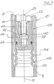
- the textile spindle shown physically in FIG. 2 comprises a tubular spindle housing 10 which is provided with an external thread 12 for rigid attachment in a bore in the spindle bench (not shown).
- a thin-walled intermediate tube 20 forming the bearing sleeve.
- a cup-shaped head piece 42 rigidly attached in the lower end 22 of the intermediate tube 20 in the lower end 22 of the intermediate tube 20 in the lower end 22 of the intermediate tube 20 in the lower end 22 of the intermediate tube 20 is a press fit 24 a cup-shaped head piece 42 rigidly attached.
- the head piece 42 forms part of a single-axis tilt joint, generally designated 40, which comprises a web 44 and a foot piece 46.
- the rocker joint 40 takes with its web 44 a position coaxial to the longitudinal axis 16 of the housing a.
- the foot 46 is pressed into the lower end 18 of the spindle housing 10.
- the tilting joint 40 is made in one piece and consists of steel, which is made flexible in the area of the web 44 by reducing the cross-section.
- a bearing bush 62 receiving a neck bearing 60 is pressed into the upper end 26 of the intermediate tube 20.
- the neck bearing 60 rotatably receives a spindle shaft 50, which will be described in more detail below and which carries a belt-driven whorl 30 and a yarn spool (not shown) on an upper part (not shown).
- the whorl 30, which is connected to the spindle shaft 50 in a rotationally rigid manner, is arranged below the neck bearing 60, i.e. with respect to the latter axially offset in the direction of the tilt joint 40.
- the shaft part 52 of the spindle shaft 50 which extends in the interior of the intermediate tube 20 below the neck bearing 60 is designed to be flexurally elastic by appropriate tapering.
- a foot bearing 64 designed as a sliding bearing which is arranged in the cup-shaped head piece 42, receives an end piece 54 of the shaft part 52, the spherically shaped end face 56 of which rests on a sliding plate 66 acting as an axial bearing.
- a pin 68 inserted into the head piece 42 supports the sliding plate 66 and therefore the entire spindle shaft 50 in the intermediate tube 20.
- the neck bearing 60 is a known radial roller bearing equipped with a circular clearance between the shaft and bearing rollers.
- the foot bearing 64 has sufficient bearing play to allow misalignments between the shaft part axis - resulting from the deflection - and the bearing axis. The latter coincides with the housing axis 16 if the intermediate tube does not fail the vertical position shown is deflected.
- the flexurally elastic shaft part 52 is surrounded by a damping device 70 provided in the intermediate tube 20 approximately in the region of the greatest deflection.
- the damping device 70 has a guide bush 72 designed as a slide bearing, a thin-walled spring sleeve 74 and a damping element 76 designed as a spiral spring.
- the guide bush 72 which receives the part 52 of the spindle shaft 50, is pressed into the spring sleeve 74 and transmits to it the forces exerted on the former.
- the spring sleeve 74 is arranged in the damping element 76 and secured by end widenings 78.
- the former distributes the forces absorbed over the length of the damping element 76, which is supported on the inside 28 of the intermediate tube 20. In the axial direction, the damping element 76 is held between a thin-walled spacer sleeve 80 standing on the head piece 42 and the bearing sleeve 62.
- At least the cup-shaped head piece 42 contains an oil bath for bearing lubrication, but this can also completely or partially fill the intermediate pipe 20, so that the damping device 70 is also located therein. Accordingly, a sealing ring 49 cooperating with the intermediate tube 20 is provided in a circumferential groove 48 provided in the head piece 42 in order to prevent oil from flowing out.
- the intermediate tube 20 in the spindle housing 10 can deflect by the radial play indicated at 19, or tip out of the housing axis 16, specifically by the lower end thereof adjoining tilt joint 40.
- the stresses occurring in the web 44 are small due to the axial distance from the neck bearing 60.
- the tilt joint Since the radial deflection of the intermediate tube or bearing sleeve 20 can take place with its parts by tipping over the tilt joint, only a fraction of the mass involved is also oscillating; the lower end of the bearing sleeve, which itself is low in mass, remains practically stationary in this regard. Due to the distance to the neck bearing and the corresponding leverage, the tilt joint is subject to low stresses. Thus, there are no high requirements to be met with regard to material and processing, in particular surface quality, and the tilting joint can be produced inexpensively. Due to the flexible design of the shaft part of the shaft itself, the deflection of the upper part of the spindle shaft around the neck bearing is realized in a simple and low-mass manner.
- FIG. 3 corresponds completely to that according to FIG. 1 with regard to the design and mounting of the spindle shaft 50, the same parts bearing the same reference numerals. However, this differs mainly in that a tilt joint 140 is provided as part of an intermediate tube 120. An independent, cup-shaped bearing element 132 is pressed into a lower end part 122 of the intermediate tube 120, which is distanced from the neck bearing and thus from the spindle bank and which replaces the head piece 42 according to FIG. 1 with regard to its function as a bearing holder.
- the tilting joint 140 comprises, in addition to the part 122, a tubular section 144 which is designed as a bellows and is thus designed to be flexible, and a tubular foot part 146 this foot part 146 in turn is rigidly fixed, in that it has a larger diameter than the part 122 and is pressed into the lower end 18.
- the exemplary embodiment according to FIG. 3 has no differences from that according to FIG. 2.
- the tilt joint 140 is designed as a spring-elastic element.
- the spring-elastic element is again integrated into the intermediate tube 220.
- a cup-shaped bearing element 232 which corresponds functionally to that according to FIG. 3, protrudes from below into the spindle housing 210 and is rigidly fastened in the lower end 216 thereof.
- a foot part 246 of the tilting joint 240 is pressed onto a collar 234 of the bearing element 232 which is tapered in diameter and which comprises a tubular section 244 designed as a bellows.
- the part of the intermediate pipe 220 surrounding the damping device 70 directly adjoins the pipe section 244.
- the resilient, resilient part of the tilting joints 140 and 240 is formed by a section of a tube designed as a bellows, specifically the intermediate tube 120 and 220, respectively, this flexibility can be used as an alternative by means of other measures which sufficiently reduce the rigidity of the corresponding pipe section, while maintaining the structure of the textile spindle described in each case.
- the tilt joint as part of another component, i.e. Integrated into the intermediate tube or into the bearing housing, this can also be designed as an independent component, corresponding to the tilt joint 40 of FIG. 1.
- the tilt joint provided according to the invention in the spindle housing instead of an arrangement between the spindle housing and the intermediate tube, as shown in FIG. 2 or an integration into the intermediate tube according to FIGS. 3 and 4, and that directly above the bearing element, the same as in Fig. 4 is pressed into the lower end of the spindle housing.
- the rigid holding element is formed by the main part of the spindle housing adjoining above the tilt joint.
- the tilt joint can be provided in the part of the intermediate tube 120 or 220 adjoining the bearing part 132 or 232, without impairing the principle of action of two mutually independent, spring-elastic degrees of freedom of the spindle shaft.
Landscapes
- Engineering & Computer Science (AREA)
- Mechanical Engineering (AREA)
- Textile Engineering (AREA)
- Spinning Or Twisting Of Yarns (AREA)
Abstract
Description
Die Erfindung betrifft eine Textilspindel nach dem Oberbegriff von Anspruch 1.The invention relates to a textile spindle according to the preamble of
Aus der EP-A1-0 209 799 ist eine solche Textilspindel, die einen Unwucht-Ausgleich durch Annäherung der wirklichen Hauptmassenträgheitsachse an die Drehachse der Spindellagerung über zwei Freiheitsgrade der Spindelwelle erlaubt, schon bekannt. Bei dieser bekannten Textilspindel ist die Spindelwelle, deren Schaft in einem Spindellagergehäuse über ein Halslager und ein Fusslager drehbar abgestützt ist, in der Lage, eine Taumelbewegung um das Halslager entgegen der Wirkung einer innerhalb des Spindellagergehäuses angeordneten Dämpfungsvorrichtung auszuführen. Das Spindellagergehäuse ist seinerseits im Abstand von der Spindelbank über eine Halterungshülse an die einen Enden von über deren Umfang verteilt angeordneten, achsparallel verlaufenden Biegefederstäben angeschlossen, deren entgegengesetzte Enden über eine weitere Halterungshülse an der Spindelbank verankert sind. Der Wirtel ist auf der Spindelwelle im Bereich des Halslagers angeordnet.Such a textile spindle is already known from EP-A1-0 209 799, which allows an unbalance compensation by approximation of the actual main mass inertia axis to the axis of rotation of the spindle bearing over two degrees of freedom of the spindle shaft. In this known textile spindle, the spindle shaft, the shaft of which is rotatably supported in a spindle bearing housing via a neck bearing and a foot bearing, is able to execute a wobbling movement around the neck bearing against the action of a damping device arranged inside the spindle bearing housing. The spindle bearing housing is in turn connected at a distance from the spindle bench via a mounting sleeve to the one end of axially parallel bending spring bars distributed over its circumference, the opposite ends of which are anchored to the spindle bench via a further mounting sleeve. The whorl is arranged on the spindle shaft in the area of the neck bearing.
Demnach kann die Spindelwelle mit dem die Garnspule tragenden Oberteil um das Halslager im Ausmass der Taumelfähigkeit gegen die Wirkung der Dämpfungsvorrichtung abkippen. Die zueinander parallel verlaufenden Biegefederstäbe gleicher Länge bilden zusammen mit den Halterungshülsen eine räumlich ausgebildete, parallelogrammartige Verbindung, deren gedachte Gelenkpaare jeweils in einer von zwei axial voneinander distanzierten Radialebenen liegen, die parallel zur Spindelbank verlaufen. Das Spindellagergehäuse lässt sich damit praktisch nur in Sinne einer Parallelverschiebung in radialer Richtung, entgegen der Federspannung der Biegefederstäbe bewegen. Da die Riemenzugkraft infolge der Wirtelanordnung im Bereich des Halslagers angreift, wird somit eine Schrägstellung der Spindelwelle bzw. ihres spulentragenden Oberteiles vermieden; das Spindellagergehäuse führt die radialen Bewegungen rechtwinklig zur Spindelbank aus.Accordingly, the spindle shaft with the upper part carrying the yarn spool can tip over the neck bearing to the extent of its ability to tumble against the action of the damping device. The mutually parallel bending spring rods of the same length form, together with the mounting sleeves, a spatially formed, parallelogram-like connection, the imaginary pairs of joints of which each lie in one of two axially spaced radial planes, that run parallel to the spindle bench. The spindle bearing housing can thus only be moved practically in the sense of a parallel displacement in the radial direction, counter to the spring tension of the spiral spring bars. Since the belt tensile force acts as a result of the whorl arrangement in the area of the neck bearing, an inclined position of the spindle shaft or its upper part carrying the spool is thus avoided; the spindle bearing housing executes the radial movements at right angles to the spindle bank.
Für den Unwucht-Ausgleich beim Spindelumlauf führt das Spindellagergehäuse in der aus der neutralen Lage parallel verschobenen Lage, zusammen mit der zugehörigen Halterungshülse, eine translatorische Drehschwingungsbewegung aus. Schon das Spindellagergehäuse für sich allein stellt eine relativ grosse Masse dar. Im überkritischen Drehzahlbereich behindert die Massenträgheit, mit zunehmender Drehzahl immer stärker, die dynamische Beweglichkeit in radialer Richtung der Spindelwelle. Damit geht eine Steigerung der unerwünschten Lagerreaktionskräfte zwischen der Spindelwelle und dem Halslager sowie dem Fusslager einher. Dies führt zu einem vorzeitigen Verschleiss der genannten Lager.In order to compensate for unbalance when rotating the spindle, the spindle bearing housing, in the position displaced parallel from the neutral position, carries out a translatory torsional vibration movement together with the associated mounting sleeve. The spindle bearing housing alone represents a relatively large mass. In the supercritical speed range, the inertia hinders the dynamic mobility in the radial direction of the spindle shaft. This is accompanied by an increase in the undesirable bearing reaction forces between the spindle shaft and the neck bearing and the foot bearing. This leads to premature wear of the bearings mentioned.
Soll trotz der geschilderten, versteifenden Wirkung der beteiligten Masse die für den Unwucht-Ausgleich erwünschte dynamische radiale Nachgiebigkeit der Spindelwelle erhalten bleiben, muss diese durch eine reduzierte Federsteifigkeit der je Doppelgelenke simulierenden Biegefederstäbe kompensiert werden. Um den entsprechenden Materialbelastungen infolge der Biegewechselspannungen zu genügen, bzw. vorzeitige Ermüdungsbrüche der Biegefederstäbe zu vermeiden, sind an deren Ausgestaltung bezüglich Werkstoff und Oberflächenbeschaffenheit hohe Anforderungen gestellt. Es leuchtet ein, dass diese Anforderungen nur mit einem entsprechenden Kostenaufwand erfüllt werden können. In einer namhaften Anzahl von Fällen verbietet sich der Einsatz solcher Textilspindeln aus Kostengründen.If, despite the described stiffening effect of the mass involved, the dynamic radial flexibility of the spindle shaft desired for balancing the unbalance is to be maintained, this must be compensated for by a reduced spring stiffness of the bending spring bars that simulate the double joints. In order to meet the corresponding material loads as a result of the alternating bending stresses, or to avoid premature fatigue fractures of the bending spring bars, high demands are made on their design with regard to material and surface quality. It it is clear that these requirements can only be met with a corresponding cost. In a well-known number of cases, the use of such textile spindles is prohibited for reasons of cost.
Aufgabe der Erfindung ist es, eine Textilspindel zu schaffen, bei welcher unter Verminderung der Lagerreaktionskräfte und durch Verminderung der Spannungsbeanspruchung der beteiligten biegeelastischen Elemente der konstruktive sowie der material- und fertigungsmässige Aufwand herabgesetzt und damit der Anwendungsbereich erweitert werden kann.The object of the invention is to provide a textile spindle in which, while reducing the reaction forces in the bearings and by reducing the stress on the bending-elastic elements involved, the design and material and production costs can be reduced and the range of application can thus be expanded.
Die erfindungsgemässe Lösung der gestellten Aufgabe erfolgt durch die Merkmale des Kennzeichens von Anspruch 1.The achievement of the object is achieved by the features of the characterizing part of
Die Lösung beruht auf der Erkenntnis, dass die Lagerreaktionskräfte am wirksamsten durch die Herabsetzung der an den Schwingungen beteiligten Masse erreicht werden kann. In diesem Sinn wirkt sich einerseits die biegeelastische Ausgestaltung der Schaftes der Spindelwelle zwischen dem Halslager und dem Fusslager aus, welche ein federelastisches Schaft-Lagerungselement und demnach seine mitschwingende Masse vermeiden lässt. Zum anderen ist bei der erfindungsgemässen Anordnung des Kippgelenkes im Abstand vom Halslager, welches die radiale Auslenkung der Spindelwelle im Halslagerbereich ermöglicht, nur ein reduzierter Teil der Gesamtmasse mitschwingend und damit für die hier interessierende Massenträgheit wirksam.The solution is based on the knowledge that the bearing reaction forces can be most effectively achieved by reducing the mass involved in the vibrations. In this sense, on the one hand, the flexurally elastic configuration of the shaft of the spindle shaft between the neck bearing and the foot bearing has an effect, which allows a spring-elastic shaft bearing element and therefore its resonating mass to be avoided. On the other hand, in the arrangement according to the invention of the tilting joint at a distance from the neck bearing, which enables the radial deflection of the spindle shaft in the neck bearing area, only a reduced part of the total mass resonates and is therefore effective for the inertia of interest here.
Für die Verminderung des konstruktiven Aufwandes fällt in Betracht, dass einerseits ein - der Schaffung des einen Freiheitsgrades dienendes - federelastisches Schaft-Lagerungsgehäuse wegfällt, und dass anderseits das Kippgelenk nur ein Einfachgelenk simulieren, bzw. eine gedachte Gelenkachse nur in einer einzigen Horizontalebene aufweisen muss. Infolge des vertikalen Abstandes des Kippgelenkes von der Spindelbank ergeben sich für die radiale Bewegung des Halslagers wesentlich herabgesetzte Spannungsbeanspruchungen in diesem "einachsig" beanspruchten Kippgelenk.To reduce the design effort, it is considered that, on the one hand, a spring-elastic shaft bearing housing, which serves to create a degree of freedom is eliminated, and that on the other hand the tilting joint only has to simulate a single joint or has an imaginary joint axis only in one single horizontal plane. As a result of the vertical distance of the tilting joint from the spindle bench, the radial movement of the neck bearing results in significantly reduced stresses in this "single-axis" stressed tilting joint.
Gemäss einer bevorzugten Ausführungsform der Erfindung ist der Wirtel an der Spindelwelle unterhalb des Halslagers angeordnet. Dies hat zur Folge, dass die Verformung der beiden federelastischen Elemente, d.h. des Schaftteiles der Spindelwelle sowie des Kippgelenkes, zu entgegengesetzten, sich praktisch kompensierenden Auslenkungen bezogen auf den Oberteil der Spindelwelle führen. So bewirkt die aus dem Abkippen der Lagerhülse resultiernde Auslenkung eine Schrägstellung der Spindelwelle etwa in einer der Riemenkraft entsprechende Richtung, währenddessen die sich aus der Durchbiegung des Schaftteiles der Spindelwelle ergebende Auslenkung des Oberteiles derselben in entgegengesetzter Richtung erfolgt. Mithin nimmt der Oberteil der Spindelwelle eine annähernd senkrechte Stellung zur Spindelbank ein.According to a preferred embodiment of the invention, the whorl is arranged on the spindle shaft below the neck bearing. As a result, the deformation of the two resilient elements, i.e. of the shaft part of the spindle shaft and of the tilt joint lead to opposite, practically compensating deflections in relation to the upper part of the spindle shaft. Thus, the deflection resulting from the tilting of the bearing sleeve causes the spindle shaft to be inclined approximately in a direction corresponding to the belt force, during which the deflection of the shaft part of the spindle shaft results in the deflection of the upper part thereof in the opposite direction. As a result, the upper part of the spindle shaft assumes an almost vertical position with respect to the spindle bank.
Es entspricht weiterhin einer bevorzugten Ausführungsform der Erfindung, dass das Kippgelenk etwa um die Länge des Schaftteiles der Spindelwelle vom Halslager distanziert ist, womit das Ausmass der biegeelastischen Deformation im Kippgelenk für eine gegebene radiale Bewegung des Halslagers aus der neutralen Stellung klein gehalten werden kann.It further corresponds to a preferred embodiment of the invention that the tilting joint is distanced from the neck bearing approximately by the length of the shaft part of the spindle shaft, so that the extent of the elastic deformation in the tilting joint can be kept small for a given radial movement of the neck bearing from the neutral position.
Nachfolgend ist die erfindungsgemässe Textilspindel anhand von mehreren Ausführungsbeispielen und unter Bezugnahme auf die Zeichnung erläutert. Es zeigen:
- Fig. 1
- eine schematische Darstellung der Deformationsverhältnisse an einer bevorzugten Ausführungsform der erfindungsgemässen Textilspindel;
- Fig. 2
- die Textilspindel nach der bevorzugten Ausführungsform im Axialschnitt; und
- Fig. 3 und 4
- je eine Teildarstellung weiterer Ausführungsformen der Textilspindel, ebenfalls im Axialschnitt, .
- Fig. 1
- a schematic representation of the deformation ratios on a preferred embodiment of the textile spindle according to the invention;
- Fig. 2
- the textile spindle according to the preferred embodiment in axial section; and
- 3 and 4
- a partial representation of further embodiments of the textile spindle, also in axial section,.
In der schematischen Darstellung der Textilspindel nach Fig. 1 ist die Neutralstellung einer Lagerungsachse mit 1 bezeichnet, die ebenfalls mit der Neutralstellung der durch ihre Achse repräsentierten Spindelwelle 2 übereinstimmt. Die Achse 1 wird von der in einer Horizontalebene veranlaufenden, gedachten Gelenkachse 3 eines biegeelastischen Kippgelenkes geschnitten. Das in Wirklichkeit mit der Spindelbank starr verbundene Kippgelenk ist bei 9 einerends als ortfest gehalten dargestellt, während an sein anderes Ende das untere Ende einer Lagerhülse 4 angeschlossen ist. In dem mithin um die Gelenkachse 3 verschwenkbaren Lagergehäuse 4 ist ein (gekrümmt dargestellter) biegeelastischer Schaftteil 2a' der Spindelwelle 2, in einem Halslager 5 und einem mit der Gelenkachse 3 zusammenfallend dargestellten Fusslager 6 drehbar gelagert.In the schematic representation of the textile spindle according to FIG. 1, the neutral position of a bearing axis is denoted by 1, which also corresponds to the neutral position of the
Im Betrieb wirkt an einem auf der Spindelwelle 2 sitzenden Wirtel 4 die Zugkraft F (entsprechend der Pfeilrichtung) eines als bei 8 angreifend angedeuteten Antriebsriemens. Die Lagerhülse 4 hat unter der Einwirkung der Zugkraft F eine gegenüber der Lagerungsachse 1 um den Winkel 1 verschwenkte Lage eingenommen. Der Ort des Angriffes 8 der Zugkraft F am Wirtel im Abstand h unterhalb des Halslagers 5 hat am Schaftteil 2a ein Biegemoment F * h verursacht. Als Folge dieses Biegemomentes, angedeutet durch die dargestellte Krümmung des Schaftteiles 2b', hat eine Verschwenkung des die Spule tragenden Oberteiles der Spindelwelle 2 um das Halslager 7 in die Achslage 2a' stattgefunden. Die Verschwenkung entspricht bezüglich Mass dem Winkel 2 und bezüglich Richtung der Zugkraft F entgegengesetzt. Bei entsprechender Dimensionierung ist die absolute Grösse der Winkel 1 und 2 gleich. Mithin nimmt der Oberteil 2a' der Spindelwelle eine zur Lagerungsachse 1 parallele Lage ein.In operation, the tensile force F (corresponding to the direction of the arrow) of a drive belt indicated as attacking at 8 acts on a
Die in Fig. 2 körperlich dargestellte Textilspindel umfasst ein rohrartiges Spindelgehäuse 10, das zur starren Befestigung in einer Bohrung der nicht dargestellten Spindelbank mit einem Aussengewinde 12 versehen ist. Im hohlen Inneren 14 des Spindelgehäuses 10 erstreckt sich praktisch über dessen volle Länge und konzentrisch zur Gehäuselängsachse 16 (der Lagerungsachse 1 in Fig. 1 entsprechend) ein die Lagerhülse bildendes, dünnwandiges Zwischenrohr 20. In das untere Ende 22 des Zwischenrohres 20 ist über einen Presssitz 24 ein becherförmiges Kopfstück 42 starr befestigt. Das Kopfstück 42 bildet Teil eines allgemein mit 40 bezeichneten einachsigen Kippgelenkes, das einen Steg 44 sowie ein Fussstück 46 umfasst. Das Kippgelenk 40 nimmt mit seinem Steg 44 eine zur Gehäuselängsachse 16 koaxiale Lage ein. Das Fusstück 46 ist in das untere Ende 18 des Spindelgehäuses 10 eingepresst. Das Kippgelenk 40 ist einstückig und besteht aus Stahl, wobei dieses durch Querschnittsreduktion im Bereich des Steges 44 biegeelastisch ausgebildet ist.The textile spindle shown physically in FIG. 2 comprises a
In das obere Ende 26 des Zwischenrohres 20 ist eine ein Halslager 60 aufnehmende Lagerbüchse 62 eingepresst. Das Halslager 60 nimmt eine nachfolgend noch näher beschriebene Spindelwelle 50 drehbar auf, die an einem nicht dargestellten Oberteil einen riemengetriebenen Wirtel 30 sowie eine Garnspule (nicht dargestellt) trägt. Der mit der Spindelwelle 50 drehstarr verbundene Wirtel 30 ist unterhalb des Halslagers 60 angeordnet, d.h. bezüglich des letzteren axial in Richtung des Kippgelenkes 40 versetzt.A
Der sich im Inneren des Zwischenrohres 20 unterhalb des Halslagers 60 erstreckende Schaftteil 52 der Spindelwelle 50 ist durch entsprechende Verjüngung biegeelastisch ausgebildet. Ein als Gleitlager ausgebildetes Fusslager 64, das im becherförmigen Kopfstück 42 angeordnet ist, nimmt ein Endstück 54 des Schaftteiles 52 auf, dessen sphärisch geformte Stirnfläche 56 auf einer als Achsiallager wirkenden Gleitplatte 66 aufliegt. Ein in das Kopfstück 42 eingesetzter Zapfen 68 stützt die Gleitplatte 66 und mithin die gesamte Spindelwelle 50 im Zwischenrohr 20 ab.
Beim Halslager 60 handelt es sich um ein bekanntes, mit Hüllenkreisspiel zwischen Wellenschaft und Lagerrollen ausgestattes Radialrollenlager. Das Fusslager 64 weist ein ausreichendes Lagerspiel auf, um Fluchtfehler zwischen Schaftteilachse - aus der Durchbiegeung resultierend - und der Lagerachse zu erlauben. Die letztere fällt mit der Gehäuseachse 16 zusammnem, wenn das Zwischenrohr nicht aus der dargestellten vertikalen Lage ausgelenkt ist.The
The
Der biegeelastische Schaftteil 52 ist etwa im Bereich der grössten Durchbiegung von einer im Zwischenrohr 20 vorgesehenen Dämpfungsvorrichtung 70 umgeben. Die Dämpfungsvorichtung 70 weist eine als Gleitlager ausgebildete Führungsbüchse 72, eine dünnwandige Federhülse 74 sowie ein als Spiralfeder ausgebildetes Dämpfungselement 76 auf. Die Führungsbüchse 72, die den Teil 52 der Spindelwelle 50 aufnimmt, ist in die Federhülse 74 eingepresst und überträgt auf diese die auf erstere ausgeübten Kräfte. Die Federhülse 74 ist im Dämpfungselement 76 angeordnet und durch Endaufweitungen 78 gesichert. Die Erstere verteilt die aufgenommenen Kräfte auf die Länge des Dämpfungselementes 76, das sich an der Innenseite 28 des Zwischenrohres 20 abstützt. In axialer Richtung ist das Dämpfungselement 76 zwischen einer auf dem Kopfstück 42 aufstehenden, dünnwandigen Distanzbüchse 80 und der Lagerbüchse 62 gehalten.The flexurally
Zumindest das becherförmige Kopfstück 42 enthält für die Lagerschmierung ein Ölbad, jedoch kann dieses auch das Zwischenrohr 20 ganz oder teilweise ausfüllen, so dass die Dämpfungsvorrichtung 70 ebenfalls in diesem liegt. Dementsprechend ist in einer im Kopfstück 42 vorgesehenen Umfangsnut 48 ein mit dem Zwischenrohr 20 zusammmenwirkender Dichtring 49 vorgesehen, um ein Ausfliessen von Öl zu verhindern.At least the cup-shaped
Im Betrieb der Spindel kann sich unter dem Einfluss der am Wirtel 30 angreifenden Antriebsriemenkraft (Riemenzugkraft) das Zwischenrohr 20 im Spindelgehäuse 10 um das bei 19 angedeutete radiale Spiel auslenken, bzw. aus der Gehäuseachse 16 abkippen und zwar um das an dessen unterem Ende anschliessende Kippgelenk 40. Die dabei im Steg 44 auftretenden Spannungsbeanspruchungen fallen infolge des axialen Abstandes zum Halslager 60 gering aus.During operation of the spindle, under the influence of the drive belt force acting on the whorl 30 (belt tensile force), the
Da die radiale Auslenkung des Zwischenrohres bzw. Lagerhülse 20 mit ihren Teilen durch Abkippen um das Kippgelenk erfolgen kann, ist nur ein Bruchteil der beteiligten Masse mitschwingend; das untere Ende der selbst ohnehin massearmen Lagerhülse bleibt diesbezüglich praktisch ortsfest. Das Kippgelenk unterliegt infolge des Abstandes zum Halslager bzw. der entsprechenden Hebelwirkung geringen Spannungsbeanspruchungen. Somit sind bezüglich Werkstoff sowie Bearbeitung, insbesondere Oberflächengüte, keine hohen Anforderungen zu erfüllen und das Kippgelenk lässt sich kostengünstig herstellen. Durch die biegeelastische Ausgestaltung des Schaftteiles der Welle selbst ist die Auslenkung des Oberteiles der Spindelwelle um das Halslager auf einfache und massearme Weise realisiert.Since the radial deflection of the intermediate tube or bearing
Das Ausführungsbeispiel nach Fig. 3 entspricht in bezug auf die Ausgestaltung und Lagerung der Spindelwelle 50 vollständig demjenigen nach Fig. 1, wobei gleiche Teile gleiche Bezugszeichen tragen. Jedoch unterscheidet sich dieses hauptsächlich dadurch, dass ein Kippgelenk 140 als Teil eines Zwischenrohres 120 vorgesehen ist. In einen vom Halslager und damit von der Spindelbank distanzierten unteren Endteil 122 des Zwischenrohres 120 ist ein selbständiges, becherförmiges Lagerelement 132 eingepresst, das das Kopfstück 42 nach Fig. 1 bezüglich seiner Funktion als Lagerhalterung ersetzt. Das Kippgelenk 140 umfasst neben dem Teil 122 einen als Faltenbalg ausgebildeten und damit biegeelastisch gestalteten Rohrabschnitt 144 sowie einen rohrförmigen Fussteil 146. Im Spindelgeäuse 10 ist dieser Fussteil 146 wiederum starr befestigt, indem derselbe gegenüber dem Teil 122 im Durchmesser erweitert und in das untere Ende 18 eingepresst ist.The embodiment according to FIG. 3 corresponds completely to that according to FIG. 1 with regard to the design and mounting of the
Funktionell weist das Ausführungsbeispiel nach Fig. 3 keine Unterschiede zu demjenigen nach Fig. 2 auf. Auch hier ist das Kippgelenk 140 als ein federelastisches Element ausgebildet.Functionally, the exemplary embodiment according to FIG. 3 has no differences from that according to FIG. 2. Here, too, the tilt joint 140 is designed as a spring-elastic element.
Im Auführungsbeispiel nach Fig. 4 ist das allgemein mit 240 bezeichnete, federelastische Element wiederum in das Zwischenrohr 220 integriert. Ein becherförmiges Lagerelement 232, das funktionell demjenigen nach Fig. 3 entspricht, ragt von unten in das Spindelgehäuse 210 hinein und ist im unteren Ende 216 desselben starr befestigt. Auf einen im Durchmesser verjüngten Kragen 234 des Lagerelementes 232 ist ein Fussteil 246 des Kippgelenkes 240 aufgepresst, das einen als Faltenbalg ausgebildeten Rohrabschnitt 244 umfasst. An den Rohrabschnitt 244 schliesst unmittelbar der die Dämpfungsvorrichtung 70 umgebende Teil des Zwischenrohres 220 an.In the exemplary embodiment according to FIG. 4, the spring-elastic element, generally designated by 240, is again integrated into the
Mit der Ausgestaltung nach dem Ausführungsbeipiel von Fig. 4 gelingt es, die am Unwuchtausgleich beteiligte, schwingende Masse der Textilspindel nochmals zu verkleinern, indem insbesondere das Lagerelement 232 und die in diesem abgestützten Teile ortsfest gehalten sind.4, it is possible to further reduce the vibrating mass of the textile spindle involved in the unbalance compensation, in particular by keeping the bearing element 232 and the parts supported in it stationary.
Während in den Ausführungsbeispielen nach Fig. 3 und 4 der biegeelastische, nachgiebige Teil der Kippgelenke 140 bzw. 240 durch einen als Faltenbalg ausgestalteten Abschnitt eines Rohres, konkret des Zwischenrohres 120 bzw. 220, gebildet ist, lässt sich diese Nachgiebigkeit alternativ durch andere, die Steifigkeit des entsprechenden Rohrabschnittes ausreichend verringernde Massnahmen erreichen und dabei den jeweils beschrieben Aufbau der Textilspindel beibehalten. So ist es beispielsweise möglich, in den betreffenden Rohrabschnitt schraubenförmig verlaufende Schlitze oder Durchbrechungen einzuarbeiten, so dass zwischen diesen als Biegefedern wirkende Stege gebildet werden.3 and 4, the resilient, resilient part of the tilting
Anstelle einer Ausgestaltung des Kippgelenkes als Teil eines anderen Bauteiles, d.h. in das Zwischenrohr oder in das Lagergehäuse integriert, lässt sich dieses, entsprechend dem Kippgelenk 40 von Fig. 1, ebenfalls als selbständiger Bauteil ausbilden.Instead of designing the tilt joint as part of another component, i.e. Integrated into the intermediate tube or into the bearing housing, this can also be designed as an independent component, corresponding to the tilt joint 40 of FIG. 1.
Grundsätzlich ist es möglich, das erfindungsgemäss vorgesehene Kippgelenk anstelle einer Anordnung zwischen dem Spindelgehäuse und dem Zwischenrohr, wie gemäss Fig. 2 bzw. einer Integration in das Zwischenrohr gemäss Fig. 3 und 4, in das Spindelgehäuse zu integrieren und zwar unmittelbar oberhalb des Lagerelementes, das gleich wie in Fig. 4 in das untere Ende des Spindelgehäuses eingepresst ist. In diesem Fall wird das starre Halteelement durch den sich oberhalb des Kippgelenkes anschliessenden Hauptteil des Spindelgehäuses gebildet.In principle, it is possible to integrate the tilt joint provided according to the invention in the spindle housing instead of an arrangement between the spindle housing and the intermediate tube, as shown in FIG. 2 or an integration into the intermediate tube according to FIGS. 3 and 4, and that directly above the bearing element, the same as in Fig. 4 is pressed into the lower end of the spindle housing. In this case, the rigid holding element is formed by the main part of the spindle housing adjoining above the tilt joint.
Für die Möglichkeiten der Ausgestaltung des Kippgelenkes bei der Integration in das Spindelgehäuse gelten die vorstehenden Ausführungen sinngemäss. Im Falle der durch schraubenfömige Schlitze gebildeten, federelastischen Stege kann es zweckmässig sein, für den mit Schlitzen oder Durchbrechungen versehenen Teil des Spindelgehäuses eine diese verschliessende Abdeckung vorzusehen, die z.B. von einem dünnwandigen Rohrstück gebildet ist.The above explanations apply mutatis mutandis to the possibilities for the design of the tilting joint during integration into the spindle housing. In the case of the spring-elastic webs formed by screw-shaped slots, it may be expedient to provide a cover for the part of the spindle housing which is provided with slots or openings, and which cover is formed, for example, by a thin-walled tube piece.
Grundsätzlich lässt sich das Kippgelenk in dem oberhalb des Lagerteiles 132 bzw. 232 anschliessenden Teil des Zwischenrohres 120 bzw. 220 vorsehen, ohne dabei das Wirkprinzip von zwei voneinander unabhängigen, federelastischen Freiheitsgraden der Spindelwelle zu beeinträchtigen.Basically, the tilt joint can be provided in the part of the
Claims (9)
Applications Claiming Priority (2)
| Application Number | Priority Date | Filing Date | Title |
|---|---|---|---|
| CH2293/93 | 1993-07-28 | ||
| CH229393 | 1993-07-28 |
Publications (1)
| Publication Number | Publication Date |
|---|---|
| EP0636718A1 true EP0636718A1 (en) | 1995-02-01 |
Family
ID=4230390
Family Applications (1)
| Application Number | Title | Priority Date | Filing Date |
|---|---|---|---|
| EP94109596A Withdrawn EP0636718A1 (en) | 1993-07-28 | 1994-06-22 | Textile spindle |
Country Status (3)
| Country | Link |
|---|---|
| US (1) | US5528892A (en) |
| EP (1) | EP0636718A1 (en) |
| JP (1) | JP2759870B2 (en) |
Families Citing this family (5)
| Publication number | Priority date | Publication date | Assignee | Title |
|---|---|---|---|---|
| DE19536874A1 (en) * | 1995-10-03 | 1997-04-10 | Novibra Gmbh | Spindle for spinning or twisting machine |
| DE19612121A1 (en) * | 1996-03-27 | 1997-10-02 | Stahlecker Fritz | Spindle assembly for spinning and twisting machines |
| DE19726216B4 (en) * | 1997-06-20 | 2007-11-22 | Novibra Gmbh | Spindle for spinning or twisting machines |
| US6273611B1 (en) * | 1998-12-03 | 2001-08-14 | Fritz Stahlecker | Bearing for spindles in spinning or twisting machines |
| DE102009031886A1 (en) * | 2009-07-06 | 2011-01-20 | Rotorcraft Ag | Spindle bearing for spinning spindle, has carrier housing with passage hole for receiving spindle shaft of spindle upper part |
Citations (6)
| Publication number | Priority date | Publication date | Assignee | Title |
|---|---|---|---|---|
| CA515112A (en) * | 1950-05-01 | 1955-07-26 | Universal Winding Company | Textile spindle |
| FR1204630A (en) * | 1957-04-27 | 1960-01-27 | Support for fast rotating spindles, especially spinning or twisting spindles | |
| FR1293897A (en) * | 1960-08-08 | 1962-05-18 | Rieter Ag Maschf | Spindle for spinning and twisting machines |
| DE3843651A1 (en) * | 1988-01-29 | 1989-08-03 | Rieter Ag Maschf | Spinning or twisting spindle |
| DE3942403A1 (en) * | 1989-12-21 | 1991-06-27 | Stahlecker Fritz | SPIDER OR TWIN SPINDLE |
| DE4121979A1 (en) * | 1990-08-08 | 1992-02-13 | Stahlecker Fritz | Spinning spindle - has discontinuous section formed in casing for damping vibration between base bearing and housing base |
Family Cites Families (17)
| Publication number | Priority date | Publication date | Assignee | Title |
|---|---|---|---|---|
| FR1150447A (en) * | 1956-05-04 | 1958-01-13 | Alsacienne Constr Meca | Spinning or twisting loom spindle |
| BE558023A (en) * | 1956-06-15 | |||
| CH379985A (en) * | 1960-04-29 | 1964-07-15 | Rieter Ag Maschf | Spinning and twisting spindle |
| US3708888A (en) * | 1971-01-14 | 1973-01-09 | Royal Oak Charcoal Co | Apparatus for activating comminuted material |
| US3797219A (en) * | 1972-03-01 | 1974-03-19 | Whitin Machine Works | Spindle bolster |
| DE2228246C3 (en) * | 1972-06-09 | 1981-02-12 | Zinser Textilmaschinen Gmbh, 7333 Ebersbach | Spinning or twisting machine |
| CH539697A (en) * | 1972-07-10 | 1973-07-31 | Uster Spindel Motoren Maschf | Textile spindle |
| DE2348908C2 (en) * | 1973-09-28 | 1982-07-22 | Spindel, Motoren & Maschinenfabrik AG, Uster, Zürich | Spinning or twisting spindle with a spindle shaft that can be driven by a whorl |
| DE2749389C3 (en) * | 1977-11-04 | 1980-11-06 | Skf Kugellagerfabriken Gmbh, 8720 Schweinfurt | Bearing for the shaft of a spinning and twisting spindle |
| DD236762A1 (en) * | 1985-04-29 | 1986-06-18 | Spindel Und Spinnfluegelfabrik | ADJUSTABLE SPINDLE FOR SPINNING OR SPINNING MACHINES |
| CH667112A5 (en) * | 1985-07-24 | 1988-09-15 | Uster Spindel Motoren Maschf | DEVICE FOR RADIAL MOVABLE FIXING OF A SPINDLE BEARING HOUSING OF A SPINDLE OR TWIN SPINDLE TO A SPINDLE BENCH. |
| US5201170A (en) * | 1989-12-23 | 1993-04-13 | Fritz Stahlecker | Spinning or twisting spindle having a spindle shaft |
| US5359842A (en) * | 1989-11-17 | 1994-11-01 | Fritz Stahlecker | Spinning or twisting shaft bearing assembly with vibration isolation connection arrangement |
| DE4036353C2 (en) * | 1989-12-23 | 2000-11-02 | Stahlecker Fritz | Spinning or twisting spindle |
| DE4004046A1 (en) * | 1990-02-10 | 1991-08-14 | Stahlecker Fritz | Spinning spindle bearing - has counter measures to eliminate excessive wear at base bearing due to tilt |
| US5119620A (en) * | 1990-05-17 | 1992-06-09 | Wilhelm Stahlecker Gmbh | Holding arrangement for a spindle of ring spinning or ring twisting machines |
| CH683430A5 (en) * | 1991-07-10 | 1994-03-15 | Rieter Ag Maschf | Spinning or twisting spindle. |
-
1994
- 1994-06-22 EP EP94109596A patent/EP0636718A1/en not_active Withdrawn
- 1994-07-27 US US08/280,999 patent/US5528892A/en not_active Expired - Fee Related
- 1994-07-28 JP JP6195906A patent/JP2759870B2/en not_active Expired - Lifetime
Patent Citations (6)
| Publication number | Priority date | Publication date | Assignee | Title |
|---|---|---|---|---|
| CA515112A (en) * | 1950-05-01 | 1955-07-26 | Universal Winding Company | Textile spindle |
| FR1204630A (en) * | 1957-04-27 | 1960-01-27 | Support for fast rotating spindles, especially spinning or twisting spindles | |
| FR1293897A (en) * | 1960-08-08 | 1962-05-18 | Rieter Ag Maschf | Spindle for spinning and twisting machines |
| DE3843651A1 (en) * | 1988-01-29 | 1989-08-03 | Rieter Ag Maschf | Spinning or twisting spindle |
| DE3942403A1 (en) * | 1989-12-21 | 1991-06-27 | Stahlecker Fritz | SPIDER OR TWIN SPINDLE |
| DE4121979A1 (en) * | 1990-08-08 | 1992-02-13 | Stahlecker Fritz | Spinning spindle - has discontinuous section formed in casing for damping vibration between base bearing and housing base |
Also Published As
| Publication number | Publication date |
|---|---|
| JP2759870B2 (en) | 1998-05-28 |
| US5528892A (en) | 1996-06-25 |
| JPH0754223A (en) | 1995-02-28 |
Similar Documents
| Publication | Publication Date | Title |
|---|---|---|
| DE4121279A1 (en) | DRILL AND / OR SLOPE | |
| WO2005092575A1 (en) | Wobble drive | |
| EP0395964B1 (en) | Apparatus for balancing inerta forces in a crank operated machine, in particular a punching machine | |
| EP0636718A1 (en) | Textile spindle | |
| DE4129797C2 (en) | Vibration damper | |
| EP1837425B1 (en) | Balancing a nipper mechanism in a combing machine | |
| DE3924373C2 (en) | Textile spindle with single-motor drive, with the rotor suspended in a damped manner | |
| DE1290856B (en) | Weight compensation of thread guide elements in spinning or twisting machines | |
| EP0209799A1 (en) | Device for radially movably fixing the casing of a spindle bearing of a spinning or twisting spindle on a spindle rail | |
| DE2348908C2 (en) | Spinning or twisting spindle with a spindle shaft that can be driven by a whorl | |
| DE4019671C2 (en) | ||
| DE4006117C2 (en) | ||
| EP1206652A1 (en) | Friction damper | |
| DE2310323A1 (en) | HIGH SPEED SPINDLE ARRANGEMENT FOR SPINNING MACHINES AND BEARINGS FOR SUCH SPINDLES | |
| DE19726216B4 (en) | Spindle for spinning or twisting machines | |
| DE19534339A1 (en) | Spinning etc. machine spindle propagating min. noise to spindle rail | |
| DE19622238C1 (en) | Paper web guide roller | |
| DE3138571C2 (en) | Copy grinder | |
| DE3835811C2 (en) | ||
| CH690441A5 (en) | Apparatus for automatic bobbin change on a spinning machine. | |
| DE2928723C2 (en) | Spinning and twisting spindle | |
| DE4234434A1 (en) | Ring spinning or twisting spindle - is driven by tangential belts or four-spindle belt drive and has bearing located between damping | |
| DE2306925A1 (en) | POWER TOOL | |
| EP0656999B1 (en) | Homokinetic coupling | |
| DE19612121A1 (en) | Spindle assembly for spinning and twisting machines |
Legal Events
| Date | Code | Title | Description |
|---|---|---|---|
| PUAI | Public reference made under article 153(3) epc to a published international application that has entered the european phase |
Free format text: ORIGINAL CODE: 0009012 |
|
| AK | Designated contracting states |
Kind code of ref document: A1 Designated state(s): CH DE ES FR IT LI |
|
| 17P | Request for examination filed |
Effective date: 19950708 |
|
| 17Q | First examination report despatched |
Effective date: 19961209 |
|
| STAA | Information on the status of an ep patent application or granted ep patent |
Free format text: STATUS: THE APPLICATION IS DEEMED TO BE WITHDRAWN |
|
| 18D | Application deemed to be withdrawn |
Effective date: 19970422 |