EP0636343B1 - Abnahmeröhrchen - Google Patents
Abnahmeröhrchen Download PDFInfo
- Publication number
- EP0636343B1 EP0636343B1 EP94305530A EP94305530A EP0636343B1 EP 0636343 B1 EP0636343 B1 EP 0636343B1 EP 94305530 A EP94305530 A EP 94305530A EP 94305530 A EP94305530 A EP 94305530A EP 0636343 B1 EP0636343 B1 EP 0636343B1
- Authority
- EP
- European Patent Office
- Prior art keywords
- container
- cap
- top portion
- extending
- skirt
- Prior art date
- Legal status (The legal status is an assumption and is not a legal conclusion. Google has not performed a legal analysis and makes no representation as to the accuracy of the status listed.)
- Expired - Lifetime
Links
Images


Classifications
-
- B—PERFORMING OPERATIONS; TRANSPORTING
- B65—CONVEYING; PACKING; STORING; HANDLING THIN OR FILAMENTARY MATERIAL
- B65D—CONTAINERS FOR STORAGE OR TRANSPORT OF ARTICLES OR MATERIALS, e.g. BAGS, BARRELS, BOTTLES, BOXES, CANS, CARTONS, CRATES, DRUMS, JARS, TANKS, HOPPERS, FORWARDING CONTAINERS; ACCESSORIES, CLOSURES, OR FITTINGS THEREFOR; PACKAGING ELEMENTS; PACKAGES
- B65D41/00—Caps, e.g. crown caps or crown seals, i.e. members having parts arranged for engagement with the external periphery of a neck or wall defining a pouring opening or discharge aperture; Protective cap-like covers for closure members, e.g. decorative covers of metal foil or paper
- B65D41/02—Caps or cap-like covers without lines of weakness, tearing strips, tags, or like opening or removal devices
- B65D41/16—Snap-on caps or cap-like covers
- B65D41/17—Snap-on caps or cap-like covers push-on and twist-off
-
- A—HUMAN NECESSITIES
- A61—MEDICAL OR VETERINARY SCIENCE; HYGIENE
- A61B—DIAGNOSIS; SURGERY; IDENTIFICATION
- A61B5/00—Measuring for diagnostic purposes; Identification of persons
- A61B5/15—Devices for taking samples of blood
- A61B5/150007—Details
- A61B5/150015—Source of blood
- A61B5/150022—Source of blood for capillary blood or interstitial fluid
-
- A—HUMAN NECESSITIES
- A61—MEDICAL OR VETERINARY SCIENCE; HYGIENE
- A61B—DIAGNOSIS; SURGERY; IDENTIFICATION
- A61B5/00—Measuring for diagnostic purposes; Identification of persons
- A61B5/15—Devices for taking samples of blood
- A61B5/150007—Details
- A61B5/150206—Construction or design features not otherwise provided for; manufacturing or production; packages; sterilisation of piercing element, piercing device or sampling device
- A61B5/150259—Improved gripping, e.g. with high friction pattern or projections on the housing surface or an ergonometric shape
-
- A—HUMAN NECESSITIES
- A61—MEDICAL OR VETERINARY SCIENCE; HYGIENE
- A61B—DIAGNOSIS; SURGERY; IDENTIFICATION
- A61B5/00—Measuring for diagnostic purposes; Identification of persons
- A61B5/15—Devices for taking samples of blood
- A61B5/150007—Details
- A61B5/150343—Collection vessels for collecting blood samples from the skin surface, e.g. test tubes, cuvettes
-
- A—HUMAN NECESSITIES
- A61—MEDICAL OR VETERINARY SCIENCE; HYGIENE
- A61B—DIAGNOSIS; SURGERY; IDENTIFICATION
- A61B5/00—Measuring for diagnostic purposes; Identification of persons
- A61B5/15—Devices for taking samples of blood
- A61B5/150007—Details
- A61B5/150351—Caps, stoppers or lids for sealing or closing a blood collection vessel or container, e.g. a test-tube or syringe barrel
-
- B—PERFORMING OPERATIONS; TRANSPORTING
- B01—PHYSICAL OR CHEMICAL PROCESSES OR APPARATUS IN GENERAL
- B01L—CHEMICAL OR PHYSICAL LABORATORY APPARATUS FOR GENERAL USE
- B01L3/00—Containers or dishes for laboratory use, e.g. laboratory glassware; Droppers
- B01L3/50—Containers for the purpose of retaining a material to be analysed, e.g. test tubes
- B01L3/508—Rigid containers without fluid transport within
- B01L3/5082—Test tubes per se
-
- C—CHEMISTRY; METALLURGY
- C07—ORGANIC CHEMISTRY
- C07C—ACYCLIC OR CARBOCYCLIC COMPOUNDS
- C07C17/00—Preparation of halogenated hydrocarbons
- C07C17/093—Preparation of halogenated hydrocarbons by replacement by halogens
- C07C17/20—Preparation of halogenated hydrocarbons by replacement by halogens of halogen atoms by other halogen atoms
- C07C17/202—Preparation of halogenated hydrocarbons by replacement by halogens of halogen atoms by other halogen atoms two or more compounds being involved in the reaction
- C07C17/206—Preparation of halogenated hydrocarbons by replacement by halogens of halogen atoms by other halogen atoms two or more compounds being involved in the reaction the other compound being HX
-
- C—CHEMISTRY; METALLURGY
- C07—ORGANIC CHEMISTRY
- C07C—ACYCLIC OR CARBOCYCLIC COMPOUNDS
- C07C17/00—Preparation of halogenated hydrocarbons
- C07C17/23—Preparation of halogenated hydrocarbons by dehalogenation
-
- C—CHEMISTRY; METALLURGY
- C07—ORGANIC CHEMISTRY
- C07C—ACYCLIC OR CARBOCYCLIC COMPOUNDS
- C07C17/00—Preparation of halogenated hydrocarbons
- C07C17/26—Preparation of halogenated hydrocarbons by reactions involving an increase in the number of carbon atoms in the skeleton
- C07C17/272—Preparation of halogenated hydrocarbons by reactions involving an increase in the number of carbon atoms in the skeleton by addition reactions
- C07C17/278—Preparation of halogenated hydrocarbons by reactions involving an increase in the number of carbon atoms in the skeleton by addition reactions of only halogenated hydrocarbons
-
- C—CHEMISTRY; METALLURGY
- C07—ORGANIC CHEMISTRY
- C07C—ACYCLIC OR CARBOCYCLIC COMPOUNDS
- C07C19/00—Acyclic saturated compounds containing halogen atoms
- C07C19/08—Acyclic saturated compounds containing halogen atoms containing fluorine
-
- A—HUMAN NECESSITIES
- A61—MEDICAL OR VETERINARY SCIENCE; HYGIENE
- A61B—DIAGNOSIS; SURGERY; IDENTIFICATION
- A61B5/00—Measuring for diagnostic purposes; Identification of persons
- A61B5/15—Devices for taking samples of blood
- A61B5/150007—Details
- A61B5/150763—Details with identification means
- A61B5/150786—Optical identification systems, e.g. bar codes, colour codes
Definitions
- the present invention relates to a collection assembly and, more particularly, to a microcollection container and cap suitable for collecting small quantities of blood from a patient and maintaining the blood in secure fashion for subsequent testing.
- Analytical instrumentation has made it possible to carry out a variety of hematological diagnostic procedures on very small quantities of blood. Because of this, a patient's finger or earlobe, for example, may be punctured and a very small quantity of blood may be rapidly collected into a container for such testing. However, in order to carry out testing and analysis on small quantities of blood, the blood must be rapidly collected prior to any coagulation thereof.
- a collection arrangement as described in U.S. Patent No. 4,397,318, has been provided wherein a cap is configured to fit the top of a microcollection container with the cap having a removable capillary scoop for engaging the puncture site and transferring blood to the container.
- a cap is configured to fit the top of a microcollection container with the cap having a removable capillary scoop for engaging the puncture site and transferring blood to the container.
- blood droplets may be left in and around the top area of the container.
- the scoop is removed from the cap and the cap is fitted onto the top of the container, the excess blood may be forced onto the outside surface of the container.
- plastic blood microcollection containers do not facilitate specimen mixing unless the surface chemistry of the container is changed to increase wettability.
- the surface chemistry of such plastic containers can be changed using O 2 plasma treatment and coating the plastic surface with a surfactant to reduce surface tension.
- changing the surface chemistry of the plastic blood collection assembly using a surfactant has been found to adversely affect test parameters and the use of plasma treatment would undesirably increase the cost of the container.
- EP-A517,119 describes a container assembly for collecting capillary blood from a lanced wound.
- the container includes an integral lip for facilitating collection from the wound with the entire length of the container from lip to curved closed end being substantially the same large diameter for rapid collection before coagulation.
- the container includes an annular integral skirt enclosing the rounded bottom of the container to provide a stable surface for maintaining the container upright on a flat surface.
- a cap for the assembly includes an annular space for receiving the top edge of the container in sealing engagement. This same annular space receives the annular container skirt to join the two parts together when the container is open.
- the cap in turn, includes an annular surface for holding the open assembly in stable erect position on a flat surface.
- the microcollection container may incorporate a hydrophilic material or a silicon may be applied to the internal surface thereof for enhancing the flow of blood introduced into the container.
- the present invention provides a collection container comprising:
- the present invention further provides a collection assembly comprising:
- the present invention is a collection assembly comprising a container and a cap.
- the cap preferably comprises a top portion, a bottom portion, and an annular skirt extending from the top portion to the bottom portion having an inner surface and an outer surface.
- the cap further includes an inner inverted skirt portion surrounded by the inner surface of the annular skirt.
- the inner inverted skirt portion is separated from the inner surface of the annular skirt by a annular space, with the cap including a cam follower positioned on the bottom portion.
- the inside surface of the annular skirt comprises at least one protrusion and the inner inverted skirt portion has a sealing ring.
- the cap further comprises a rim extending from the outer surface of the annular skirt.
- the container preferably comprises a open top portion, a closed bottom portion, a sidewall extending from the top portion to the bottom portion and an open end associated with the top portion having an integral collector.
- the integral collector is a scoop that is the same diameter as the inner diameter of the container so that no air vent is required.
- the container further includes a cap seating flange associated with the outer diameter of the top portion of the container and an extending annular skirt associated with the bottom portion.
- a reservoir is positioned within the cap seating flange and at least one lug is located in the reservoir.
- the container also includes a locking ring associated between the integral collector and the cap seating flange.
- the collection assembly includes means for securing the inner surfaces of the cap to the top portion of the container by the interaction of the protrusions of the cap with the locking ring of the container and the sealing ring of the cap with the inside surface of the top portion of the container.
- the collection assembly also includes means for unsecuring the cap from the container by a cam arrangement on the cap and container. This cam arrangement assists in substantially reducing fluid splatter from the container when the cap is removed from the container.
- the cam arrangement includes at least one cam follower positioned on the bottom portion of the cap and at least one cam surface positioned in the cap seating flange of the container.
- This action which may cause an audible-snap, in turn seals the container by compressing the protrusions of the cap against the locking ring of the container and the sealing ring of the cap against the inside surface of the top portion of the container to form a non-permanent lock and to substantially prevent the outer surface of the top portion of the container from making contact with the inside surface of the cap's annular skirt.
- the cap and container are then unsecured in a twist off manner by applying a rotational force to the cap.
- a rotational force is applied to the cap and a downwardly force applied to the container along the longitudinal axis. This causes the cam follower to rise on the cam surface and in turn the cap is unsecured from the container.
- An important advantage of the present invention is that the rotational force applied to the cap can be bi-directional, that is clockwise or counter-clockwise.
- the collection assembly of the present invention is preferably used in micro-centrifuges.
- an extension may be secured and unsecured to the bottom portion of the container.
- the extension increases the length dimension of the container.
- the container may be compatible with standard clinical centrifuges.
- An advantage of the present invention is that any excess fluid on the outside surface of the integral collector is directed downwardly into the cap seating flange by the inner surface of the annular skirt of the cap when a downward force is applied to the cap as the cap and container are being secured. Therefore, radial spray of excess fluids are minimized.
- the cap may be secured and unsecured to the bottom portion of the container.
- the annular space in the cap between the annular skirt and inverted skirt allows the cap to be removably secured with the bottom portion of the container by receiving the annular skirt of the container.
- Still another advantage of the invention is that the recessed inverted skirt and the sealing-ring substantially reduces cap contact with fluid collected in the container. Therefore the inner surfaces of the cap may be minimally exposed to fluid collected in the container when the cap is secured to the top portion of the container.
- the outer surface of the cap may preferably be configured to substantially limit movement or rolling of the cap or the assembly. This applies whether the cap is positioned with the top portion or bottom portion of the container.
- Still another advantage of the present invention is that when the cap is secured to the container, the rim of the cap substantially prevents contamination to the specimen inside the container.
- another advantage of the collection assembly according to the present invention is the fine matte finish on the inside surface of the container, which decreases the total interaction between a blood specimen in the container and the hydrophobic polypropylene material of which the container is made.
- the matte finish on the inside of the container decreases the surface tension between the container and the specimen so that the specimen does not attach to one end of the container, but rather mixes freely within the container when being mixed on a mechanical device.
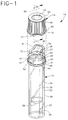
- FIG. 1 is a perspective view of the preferred collection assembly illustrating the container with the cap unsecured.
- FIG. 2 is a side elevational view of the container of FIG.1, partially in section of the cam surface area.
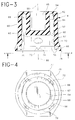
- FIG. 3 is an enlarged cross sectional view of the cap of FIG. 1, taken along line 3-3 thereof.
- FIG. 4 is a bottom view of the cap of FIG. 1.
- FIG. 5 is a side elevational view, partially in section of the collection assembly of FIG. 1 with the cap secured to the top portion of the container.
- FIG. 6 is a side elevational view, partially in section of the collection assembly of FIG. 1 with the cap removably secured to the bottom portion of the container.
- FIG. 7 is a perspective view of the preferred collection assembly of FIG. 1 and an optional extension that may be removably secured to the collection assembly.
- FIG. 8 is a side elevational view, partially in section of the collection assembly of FIG. 7 with an extension removably secured to the bottom portion of the container.
- FIG. 1 illustrates a collection assembly 10 comprising a container 12 and a cap 14 .
- container 12 has a sidewall 22 having an outer surface 24 and an inner surface 26 .
- the sidewall extends from an upper portion 28 to a lower portion 30 .
- Upper portion 28 includes an open end 31 and an inner surface 27 with a top surface 32 having an integral lip portion 34 with a receiving edge 36 .
- Lower portion 30 comprises a closed bottom end 38 and an annular skirt 37 extending from the closed bottom end and outer surface 24 to define a compartment area 39 .
- Annular skirt 37 provides a means for allowing the container to be placed upright on a flat surface.
- Upper portion 28 has a cap seating flange 40 positioned around the outer surface of the container which defines a well or trough 42 and an outer surface 41 .
- the cap seating flange has an upper surface edge 43 and a plurality of lugs 44 each having a cam surface 46 .
- a container having only one projecting lug is within the purview of the instant invention, a plurality of lugs is preferred.
- lugs 44 of this embodiment are triangularly shaped.
- a locking ring 48 positioned between receiving edge 36 of integral lip portion 34 and cap seating flange 40 .
- the locking ring has an upper edge 50 and a lower edge 52 .
- Cap 14 as shown in FIG. 3, has a top surface 54 , a bottom stop ledge 56 and an annular outer skirt 58 extending from the top surface to the bottom stop ledge.
- the annular outer skirt has an outer wall surface 60 and an inner wall surface 62 .
- a shield 66 extends from the outer wall surface of the annular outer skirt and has an outer surface or circumference 76 .
- cap 14 also has an inner annular inverted recessed skirt portion 64 that extends from top portion 54 to a bottom surface 63 .
- the inverted recessed skirt portion defines a compartment or cup area 65 on the top portion of the cap.
- the inner wall surface of the annular outer skirt and the inner annular inverted recessed skirt are spaced from each other to define an annular space 68 .
- the cap further includes, a plurality of circumferentially spaced protrusions 70 positioned on inner wall surface 62 and a sealing ring 67 positioned on inverted recessed skirt portion 64 .
- Projecting lugs 72 are located on bottom stop ledge 56 wherein each lug comprises a cam follower surface 74 .
- lugs 72 of this embodiment are triangularly shaped.
- flats 77 are positioned on the outer surface of shield 66 .
- the flats substantially prevent the cap from rolling and provide a convenient grasping surface for ready removal and placement of the cap on the container.
- a shield with a smooth outer circumference without flats is within the purview of the instant invention, a shield with an outer surface with flats is preferred.
- Cam follower surface 74 and cam surface 46 are configured so that a downwardly rotational force applied to cap 14 about longitudinal axis 80 causes cam follower 74 to contact cam surface 46 .
- Cap 14 is snapped onto the top portion of the container as guided by cam follower surface 74 and cam surface 46 .
- Cap 14 is removably secured to container 12 by protrusions 70 and sealing ring 67 as they bear respectfully against lower edge 52 of the locking ring and inner surface 27 of the container.
- the position of the protrusions and sealing ring of the cap with the container forms space 69 between the outer surface of the top portion of the container and the inner wall surface of the cap's annular outer skirt. Therefore, wiping down of any fluid on the container's outer surface is substantially prevented.
- the cap is unsecured from the container in a twist-off manner by applying a rotational force about longitudinal axis 80 while holding the container. Rotation of the cap with respect to the container causes cam follower surface 74 to rise on cam surface 46 and in turn the cap is unsecured from the container.
- the rotational force applied to the cap can be bi-directional, that is clockwise or counter-clockwise.
- cap 14 is readily compatible with skirt 37 on the lower portion of the container.
- Space 68 of the cap receives the skirt of the container.
- extension 90 is optionally available to be inserted into skirt 37 on the lower portion of container 12 .
- the extension may be optionally used to make the collection assembly compatible with standard centrifuges or the need for additional space for labeling. Multiple extensions may be used if needed.
- the collection assembly of the invention may be made of a molded thermoplastic material so that the specimen collected may be readily viewed.
- Representative materials include, for example, polyethylene, polypropylene and polyvinyl chloride.
- the collection container may incorporate a hydrophilic material or a silicon may be applied to the internal surface thereof for enhancing the flow of blood introduced into the container.
- caps which are colored to define specific forms of fluid collection containers containing materials for one reason or another or for defining the kind of examination to be conducted on the specimen collected
- transparent caps may be provided.
- the dimensions of the container are such as to provide space for labeling which may be important for identifying the collected specimens.
- Another important feature of the present invention is the mixability provided by the collection assembly when being mixed on a mechanical device.
- the inventors have found that if inner surface 26 of container 12 is smooth, the surface tension between inner surface 26 and the specimen in container 12 is too high and results in the specimen failing to mix when placed on a mechanical rotator or rocker. It has been found that if the volume of specimen is small it will hang up in one end of container 12 and prevent mixing of the specimen.
- the present invention solves the above-described problem by including a fine matte finish on inner surface 26 of container 12 which has been found to decrease the total interaction between the specimen and inner surface 26 .
- the matte finish can be made on inner surface 26 when container 12 is being manufactured by using a mold core that has been pretreated with an abrasive that forms a surface finish corresponding to the Society of Plastics Industry surface finish #4.
- the pretreated mold core molds container 12 from hydrophobic polypropylene material, the desired matte finish is molded into inner surface 26 .
- the matte finish on inner surface 26 decreases the total interaction between a liquid specimen in container 12 and the inner surface 26 of container 12 by changing the contact angle between the liquid specimen and inner surface 26 .
- the matte finish therefore provides for continuous mixing of the liquid specimen in container 12 as container 12 is rotated on a 360° mechanical rotator or a mechanical rocker.
Landscapes
- Health & Medical Sciences (AREA)
- Chemical & Material Sciences (AREA)
- Organic Chemistry (AREA)
- Life Sciences & Earth Sciences (AREA)
- Engineering & Computer Science (AREA)
- General Health & Medical Sciences (AREA)
- Hematology (AREA)
- Surgery (AREA)
- Veterinary Medicine (AREA)
- Biophysics (AREA)
- Biomedical Technology (AREA)
- Heart & Thoracic Surgery (AREA)
- Medical Informatics (AREA)
- Molecular Biology (AREA)
- Physics & Mathematics (AREA)
- Animal Behavior & Ethology (AREA)
- Chemical Kinetics & Catalysis (AREA)
- Public Health (AREA)
- Pathology (AREA)
- Mechanical Engineering (AREA)
- Dermatology (AREA)
- Manufacturing & Machinery (AREA)
- Analytical Chemistry (AREA)
- Clinical Laboratory Science (AREA)
- Sampling And Sample Adjustment (AREA)
- Measurement Of The Respiration, Hearing Ability, Form, And Blood Characteristics Of Living Organisms (AREA)
- Investigating Or Analysing Biological Materials (AREA)
- Closures For Containers (AREA)
Claims (9)
- Entnahmebehälter (12), der folgende Komponenten umfaßt:einen offenen oberen Abschnitt (28);einen geschlossenen unteren Abschnitt (30);eine Seitenwand (22), die sich von dem oberen Abschnitt (28) zu dem unteren Abschnitt (30) erstreckt und eine Innenfläche (20) und eine Außenfläche (24) hat, wobei die Innenfläche (26) das Mischen einer darin enthaltenen Probe fördert; undeinen integralen Sammler (34), der von dem oberen Abschnitt (28) ausgeht;
dadurch gekennzeichnet, daß die Innenfläche (22) texturiert ist, um das Mischen zu fördern, wobei die Textur auf der Innenfläche des Behälters ein Matt-Finish ist, das die Gesamtwechselwirkung zwischen der Probe und der Innenfläche herabsetzt. - Behälter nach Anspruch 1, der außerdem einen ringförmigen Rand (37) umfaßt, der von dem geschlossenen unteren Abschnitt (30) und der Außenfläche (24) der Seitenwand (22) ausgeht.
- Behälter nach Anspruch 2, der außerdem einen Lippenabschnitt (34) und eine aufnehmende Kante (36) umfaßt, die dem integralen Sammler zugeordnet sind.
- Behälter nach Anspruch 3, der außerdem einen Klemmring (48) umfaßt, der zwischen dem integralen Sammler und einem Kappenauflageflansch (40) auf der Außenfläche (24) der Seitenwand (22) positioniert ist.
- Behälter nach Anspruch 4, der außerdem eine Oberkante (50) und eine Unterkante (52) auf dem Klemmring umfaßt.
- Behälter nach Anspruch 4, der außerdem folgende Komponenten umfaßt:ein Reservoir (42), das innerhalb des Kappenauflageflanschs (40) positioniert ist; undwenigstens einen Ansatz (44), der innerhalb des Reservoirs (42) positioniert ist.
- Entnahmevorrichtung (10), die folgende Komponenten umfaßt:eine Kappe (14), die folgendes umfaßt: eine Längsachse, einen oberen Abschnitt, einen unteren Abschnitt (54), einen ringförmigen Rand (58), der sich von dem oberen Abschnitt zu dem unteren Abschnitt erstreckt und eine Innenfläche (62) und eine Außenfläche (64) hat, einen umgekehrten inneren Randabschnitt (64), der durch die Innenfläche (62) des ringförmigen Rands (58) umschlossen wird und sich von dem oberen Abschnitt hin zu dem unteren Abschnitt erstreckt, und einen ringförmigen Raum (68) zwischen der Innenfläche (62) des ringförmigen Rands (58) und dem umgekehrten Randabschnitt (64); undeinen Behälter (12), der folgendes umfaßt: einen offenen oberen Abschnitt (28), einen geschlossenen unteren Abschnitt (30), eine Seitenwand (22), die sich von dem oberen Abschnitt zu dem unteren Abschnitt erstreckt und eine Innenfläche (26) und eine Außenfläche (24) hat, einen integralen Sammler, der von dem oberen Abschnitt ausgeht, und einen Kappenauflageflansch (40), welcher der Außenfläche der Seitenwand zugeordnet ist,
bei der die Innenfläche (26) des Behälters (12) das Mischen einer darin enthaltenen Probe fördert;
dadurch gekennzeichnet, daß die Innenfläche (22) texturiert ist, um das Mischen zu fördern, wobei die Textur auf der Innenfläche des Behälters ein Matt-Finish ist, das die Gesamtwechselwirkung zwischen der Probe und der Innenfläche herabsetzt. - Vorrichtung nach Anspruch 7, die außerdem folgende Komponenten umfaßt:einen Klemmring (48) auf der Außenfläche des Behälters (12), der zwischen dem integralen Sammler und dem Kappenauflageflansch positioniert ist;wenigstens einen Vorsprung (70), der auf der Innenfläche des ringförmigen Rands (58) der Kappe (14) positioniert ist;einen Dichtungsring (67) auf dem umgekehrten inneren Randabschnitt (64) der Kappe, undeinen umgebogenen Rand, der von der Außenfläche des ringförmigen Rands (58) der Kappe ausgeht;
bei welcher der Vorsprung (70) an dem Klemmring (48) des Behälters anliegt, der Dichtungsring an der Innenfläche des oberen Abschnitts des Behälters anliegt und der umgebogene Rand mit dem Kappenauflageflansch aneinander stößt, wenn die Kappe über dem offenen oberen Abschnitt des Behälters aufgesetzt wird. - Vorrichtung nach Anspruch 7 oder 8, bei der das Matt-Finish ein Oberflächen-Finish Nr. 4 der Society of Plastics Industry ist.
Applications Claiming Priority (3)
| Application Number | Priority Date | Filing Date | Title |
|---|---|---|---|
| US08/060,787 US5384096A (en) | 1993-05-12 | 1993-05-12 | Microcollection tube assembly |
| US9967893A | 1993-07-29 | 1993-07-29 | |
| US99678 | 1993-07-29 |
Publications (2)
| Publication Number | Publication Date |
|---|---|
| EP0636343A1 EP0636343A1 (de) | 1995-02-01 |
| EP0636343B1 true EP0636343B1 (de) | 1998-09-09 |
Family
ID=51946298
Family Applications (2)
| Application Number | Title | Priority Date | Filing Date |
|---|---|---|---|
| EP94106934A Expired - Lifetime EP0627197B1 (de) | 1993-05-12 | 1994-05-04 | Aufnahmevorrichtung |
| EP94305530A Expired - Lifetime EP0636343B1 (de) | 1993-05-12 | 1994-07-27 | Abnahmeröhrchen |
Family Applications Before (1)
| Application Number | Title | Priority Date | Filing Date |
|---|---|---|---|
| EP94106934A Expired - Lifetime EP0627197B1 (de) | 1993-05-12 | 1994-05-04 | Aufnahmevorrichtung |
Country Status (7)
| Country | Link |
|---|---|
| US (2) | US5384096A (de) |
| EP (2) | EP0627197B1 (de) |
| JP (2) | JP2601627B2 (de) |
| AU (2) | AU671198B2 (de) |
| CA (2) | CA2122683C (de) |
| DE (2) | DE69406978T2 (de) |
| ES (1) | ES2125412T3 (de) |
Families Citing this family (79)
| Publication number | Priority date | Publication date | Assignee | Title |
|---|---|---|---|---|
| US5384096A (en) * | 1993-05-12 | 1995-01-24 | Becton, Dickinson And Company | Microcollection tube assembly |
| US5881596A (en) * | 1993-09-30 | 1999-03-16 | Itochu Corporation | Urine sampling vessel |
| US5527513A (en) * | 1994-04-08 | 1996-06-18 | Becton Dickinson And Company | Collection assembly |
| DE4412286A1 (de) * | 1994-04-09 | 1995-10-12 | Boehringer Mannheim Gmbh | System zur kontaminationsfreien Bearbeitung von Reaktionsabläufen |
| JP3295550B2 (ja) * | 1994-09-16 | 2002-06-24 | 富士写真フイルム株式会社 | 飛出し防止用封止具を備えた乾式分析フィルム用カートリッジ |
| USD382482S (en) * | 1995-03-31 | 1997-08-19 | Lever Brothers Company, Division Of Conopco, Inc. | Bottle closure |
| USD381911S (en) * | 1995-03-31 | 1997-08-05 | Lever Brothers Company, Division Of Conopco, Inc. | Bottle closure |
| US6315145B1 (en) | 1995-07-13 | 2001-11-13 | Sticksafe Llc | Lid for a specimen container that is adapted to minimize spills and leaks |
| US5904677A (en) * | 1995-07-13 | 1999-05-18 | Drummey; Thomas Hartnett | Sterile specimen capture device |
| US5766936A (en) * | 1995-09-08 | 1998-06-16 | Becton Dickinson And Company | Reusable vented flask cap cover |
| US5595907A (en) * | 1995-09-08 | 1997-01-21 | Becton, Dickinson And Company | Reusable vented flask cap cover |
| US5638971A (en) * | 1995-11-07 | 1997-06-17 | Justesen; Jeffrey L. | Vacuum seal container |
| US5856194A (en) | 1996-09-19 | 1999-01-05 | Abbott Laboratories | Method for determination of item of interest in a sample |
| US5795784A (en) | 1996-09-19 | 1998-08-18 | Abbott Laboratories | Method of performing a process for determining an item of interest in a sample |
| US5756049A (en) * | 1996-10-25 | 1998-05-26 | Hach Company | Water testing capsule using water soluble film membranes |
| DE19647673C2 (de) * | 1996-11-19 | 2000-08-24 | Sarstedt Ag & Co | Probengefäß zur Blutabnahme |
| US5893476A (en) * | 1997-04-16 | 1999-04-13 | Estar Technologies Ltd. | Sealing closure for sample tubes |
| US5901873A (en) * | 1997-04-25 | 1999-05-11 | Beckman Instruments, Inc. | Self-seating self-sealing labware adapter |
| USD401697S (en) | 1997-05-21 | 1998-11-24 | Abbott Laboratories | Container |
| US5915583A (en) * | 1997-05-21 | 1999-06-29 | Abbott Laboraties | Container |
| US5942191A (en) | 1997-07-14 | 1999-08-24 | Becton, Dickinson And Company | Body fluid collection vessel having reduced capacity |
| US5948365A (en) * | 1997-09-12 | 1999-09-07 | Becton Dickinson And Company | Collection container assembly |
| US6612997B1 (en) | 1997-09-12 | 2003-09-02 | Becton, Dickinson And Company | Collection container assembly |
| US6179787B1 (en) * | 1997-09-12 | 2001-01-30 | Becton Dickinson And Company | Collection container assembly |
| CA2242940A1 (en) * | 1997-09-12 | 1999-03-12 | Karin E. Kelly | Collection container assembly |
| US20020156439A1 (en) * | 1997-09-12 | 2002-10-24 | Michael J. Iskra | Collection container assembly |
| US5955032A (en) * | 1997-09-12 | 1999-09-21 | Becton Dickinson And Company | Collection container assembly |
| US6371319B2 (en) * | 1997-09-22 | 2002-04-16 | Abbott Laboratories | Closure system for containers |
| US6080366A (en) * | 1998-03-02 | 2000-06-27 | Becton, Dickinson And Company | Disposable blood tube holder |
| US6074883A (en) * | 1998-03-02 | 2000-06-13 | Becton, Dickinson And Company | Method for using disposable blood tube holder |
| US6562300B2 (en) | 1998-08-28 | 2003-05-13 | Becton, Dickinson And Company | Collection assembly |
| US6716396B1 (en) | 1999-05-14 | 2004-04-06 | Gen-Probe Incorporated | Penetrable cap |
| US6426049B1 (en) * | 1999-07-09 | 2002-07-30 | Becton, Dickinson And Company | Collection assembly |
| USD444885S1 (en) | 1999-08-06 | 2001-07-10 | Becton, Dickinson And Company | Stackable tube assembly |
| USD444886S1 (en) | 1999-08-06 | 2001-07-10 | Becton, Dickinson And Company | Stackable tube assembly |
| USD444887S1 (en) | 1999-08-06 | 2001-07-10 | Becton, Dickinson And Company | Stackable tube assembly |
| USD444568S1 (en) | 1999-08-06 | 2001-07-03 | Becton, Dickinson And Company | Stackable tube assembly |
| USD445908S1 (en) | 1999-08-06 | 2001-07-31 | Becton, Dickinson And Company | Stackable tube assembly |
| US6358476B1 (en) | 1999-09-23 | 2002-03-19 | Sharon A. Innamorato | Microcollection tube assembly |
| JP4559003B2 (ja) * | 1999-10-20 | 2010-10-06 | キアジェン ノース アメリカン ホールディングス,インコーポレイティド | 混合・注入装置及びその容器 |
| US6221307B1 (en) | 1999-11-10 | 2001-04-24 | Becton Dickinson And Company | Collection container assembly |
| USD457247S1 (en) | 2000-05-12 | 2002-05-14 | Gen-Probe Incorporated | Cap |
| US7854896B2 (en) * | 2001-09-25 | 2010-12-21 | Becton, Dickinson And Company | Closed system storage plates |
| US7028858B2 (en) * | 2002-02-19 | 2006-04-18 | Stull Technologies, | Quick-twist pop-off closure |
| US7482116B2 (en) | 2002-06-07 | 2009-01-27 | Dna Genotek Inc. | Compositions and methods for obtaining nucleic acids from sputum |
| EP1534595A4 (de) * | 2002-06-25 | 2009-04-08 | Stull Technologies | SCHNELLDREHVERSCHLUSS MIT ORIGINALITûTSSICHERUNG |
| US20040013574A1 (en) * | 2002-07-18 | 2004-01-22 | Becton, Dickinson And Company | Specimen collection tube assembly with differentiated components |
| AU2003268274A1 (en) * | 2002-09-04 | 2004-03-29 | Becton, Dickinson And Company | Collection assembly |
| US7083058B2 (en) * | 2003-01-31 | 2006-08-01 | Abbott Laboratories | Linerless sealing closure for a container |
| US7270787B2 (en) * | 2003-07-31 | 2007-09-18 | Thermo Fisher Scientific (Asheville) Llc | Centrifuge sample jar and closure |
| IE20040076A1 (en) * | 2004-02-09 | 2005-08-10 | Loctite R & D Ltd | A dispensing nozzle and cap |
| WO2007004203A1 (en) | 2005-07-05 | 2007-01-11 | Loctite R & D Limited | A container for holding and dispensing a curable product |
| USD596034S1 (en) * | 2006-11-08 | 2009-07-14 | Geka Brush Gmbh | Cosmetic container |
| CN101688874A (zh) * | 2007-07-12 | 2010-03-31 | 希森美康株式会社 | 标本容器 |
| CN102282078B (zh) * | 2008-03-05 | 2014-03-05 | 贝克顿·迪金森公司 | 共模制可刺破塞子及其制造方法 |
| WO2010036387A2 (en) | 2008-03-05 | 2010-04-01 | Becton, Dickinson And Company | Capillary action collection device and container assembly |
| JP5506168B2 (ja) * | 2008-08-04 | 2014-05-28 | 村角工業株式会社 | 検体収容容器 |
| USD621522S1 (en) | 2009-09-03 | 2010-08-10 | Becton, Dickinson And Company | Pierceable collection container device |
| USD640796S1 (en) | 2009-03-05 | 2011-06-28 | Becton, Dickinson And Company | Collection container |
| US8603417B2 (en) * | 2009-08-24 | 2013-12-10 | Michael J. Cefaratti | Combination tube and cap for storage and transport of fluid samples |
| USD634024S1 (en) | 2010-01-22 | 2011-03-08 | Becton, Dickinson And Company | Closure for a specimen container having an indicator surface |
| USD662216S1 (en) | 2010-01-22 | 2012-06-19 | Becton, Dickinson And Company | Closure or a specimen container having an indicator surface |
| USD645972S1 (en) | 2010-01-25 | 2011-09-27 | Becton, Dickinson And Company | Specimen collection container having a label |
| USD640797S1 (en) | 2010-01-25 | 2011-06-28 | Becton, Dickinson And Company | Specimen collection container having a label |
| JP5735361B2 (ja) | 2010-08-02 | 2015-06-17 | シスメックス株式会社 | 検体処理装置 |
| US8973293B2 (en) | 2010-11-19 | 2015-03-10 | Becton, Dickinson And Company | Specimen container label for automated clinical laboratory processing systems |
| USD641491S1 (en) * | 2010-12-02 | 2011-07-12 | Lightintegra Technology Inc. | Container |
| US8460620B2 (en) * | 2010-12-03 | 2013-06-11 | Becton, Dickinson And Company | Specimen collection container assembly |
| CN106442039B (zh) | 2011-06-19 | 2020-08-07 | 阿博根公司 | 用于样品采集的装置、溶液和方法 |
| AT514833B1 (de) * | 2013-10-11 | 2015-07-15 | Greiner Bio One Gmbh | Abnahmebaugruppe, insbesondere für Blutproben |
| USD850647S1 (en) * | 2016-08-19 | 2019-06-04 | Dna Genotek Inc. | False bottom tube with cap and plug |
| JP7092747B2 (ja) | 2016-08-24 | 2022-06-28 | ベクトン・ディキンソン・アンド・カンパニー | 血液の付着流のための装置 |
| CN107121559B (zh) * | 2017-05-09 | 2018-11-23 | 深圳市帝迈生物技术有限公司 | 可对末梢血进行全自动进样血细胞分析的测量方法和装置 |
| USD998170S1 (en) * | 2019-04-10 | 2023-09-05 | Inveox Gmbh | Sample container |
| CN110811642B (zh) * | 2019-09-26 | 2021-09-17 | 广州阳普医疗科技股份有限公司 | 一种采血装置 |
| USD965174S1 (en) * | 2020-07-17 | 2022-09-27 | Zymo Research Corporation | Specimen collection tube |
| US20230330677A1 (en) * | 2020-09-08 | 2023-10-19 | SeLux Diagnostics, Inc. | Devices, systems, and methods for sample tube processing |
| CN116761530B (zh) * | 2021-01-28 | 2026-03-06 | 阿希姆·海涅 | 具有盖和分配装置的容器 |
| USD999400S1 (en) * | 2021-03-05 | 2023-09-19 | Zymo Research Corporation | Specimen collection tube |
Family Cites Families (38)
| Publication number | Priority date | Publication date | Assignee | Title |
|---|---|---|---|---|
| US3005564A (en) * | 1959-10-12 | 1961-10-24 | Biolog Res Inc | Laboratory equipment |
| US3136458A (en) * | 1961-02-27 | 1964-06-09 | Ruetz Karl | Container including a neck with a pouring opening and closing device for the same |
| US3265296A (en) * | 1964-03-06 | 1966-08-09 | Internat Equipment Company | Plastic centrifuge bottles and caps therefor |
| US3252446A (en) * | 1964-08-13 | 1966-05-24 | Carter S Ink Co | Friction closure |
| US3372834A (en) * | 1966-01-24 | 1968-03-12 | Robert A. Ayotte | Container and closure assembly |
| US3308039A (en) * | 1966-02-15 | 1967-03-07 | Allergan Pharma | Disposable culturing device |
| FR1520693A (fr) * | 1967-03-01 | 1968-04-12 | Oreal | Nouveau dispositif de bouchage pour flacons ou récipients analogues |
| US3419179A (en) * | 1967-06-07 | 1968-12-31 | Brunswick Corp | Captive cap specimen vial |
| US3706306A (en) * | 1971-03-03 | 1972-12-19 | Harold J Berger | Combination blood sampling vacuum syringe centrifuge container and specimen cup |
| US3902477A (en) * | 1973-09-26 | 1975-09-02 | Becton Dickinson Co | Blood specimen container |
| US3901400A (en) * | 1974-02-04 | 1975-08-26 | Continental Can Co | Childproof closure |
| US3910444A (en) * | 1974-06-06 | 1975-10-07 | Clark Mfg Co J L | Container having snap-on, twist-off cap |
| US3945525A (en) * | 1974-06-06 | 1976-03-23 | American Hospital Supply Corporation | Closure system for medical liquid container having low-torque breakaway ring |
| US3982651A (en) * | 1974-11-18 | 1976-09-28 | W. Braun Company | Container and closure cap therefor |
| US4171057A (en) * | 1978-10-30 | 1979-10-16 | Sunbeam Plastics Corporation | Child-resistant medicine vial |
| GB2041892A (en) * | 1979-02-09 | 1980-09-17 | United Glass Ltd | Containers & Closures |
| US4298129A (en) * | 1980-05-02 | 1981-11-03 | Morton Stull | Childproof, snap-on, twist-off safety cap and container |
| US4335823A (en) * | 1981-01-26 | 1982-06-22 | Sunbeam Plastics Corporation | Child-resistant package |
| US4411163A (en) * | 1981-07-27 | 1983-10-25 | American Hospital Supply Corporation | Ventable sample collection device |
| US4397318A (en) * | 1981-08-10 | 1983-08-09 | Becton Dickinson And Company | Blood collector for microcollection container |
| US4390111A (en) * | 1982-02-08 | 1983-06-28 | Robbins Scientific Corporation | Sealable vial |
| US4399920A (en) * | 1982-03-11 | 1983-08-23 | Owens-Illinois, Inc. | Child resistant package |
| JPS59274A (ja) * | 1982-06-25 | 1984-01-05 | Fujitsu Ltd | ピンクツシヨン歪補正回路 |
| US4799599A (en) * | 1982-07-30 | 1989-01-24 | Ciba Corning Diagnostics Corp. | Specimen cup and cap assembly for clinical analyzer |
| US4576185A (en) * | 1983-12-05 | 1986-03-18 | Terumo Medical Corporation | Collection device for capillary blood |
| US4620549A (en) * | 1985-01-25 | 1986-11-04 | Becton, Dickinson And Company | Blood collection assembly |
| DE3541041A1 (de) * | 1985-11-19 | 1987-05-21 | Sarstedt Kunststoff | Blutsammelgefaess |
| JPH071050Y2 (ja) * | 1987-09-05 | 1995-01-18 | 株式会社新和製作所 | 液体化粧料等の収納容器 |
| JPH074207Y2 (ja) * | 1987-09-24 | 1995-02-01 | 東京ライト工業株式会社 | 蓋付き容器 |
| JPH0617682Y2 (ja) * | 1988-02-29 | 1994-05-11 | フィグラ株式会社 | 容器の閉蓋装置 |
| US4804096A (en) * | 1988-04-22 | 1989-02-14 | Harding Claude J | Tamper resistant container |
| JP2699087B2 (ja) * | 1988-07-18 | 1998-01-19 | フィグラ株式会社 | 容器蓋の開閉装置 |
| US4967763A (en) * | 1989-03-13 | 1990-11-06 | Becton, Dickinson And Company | Platelet stable blood collection assembly |
| JPH04145936A (ja) * | 1990-10-05 | 1992-05-19 | Konica Corp | 液体撹拌混合方法及び液体撹拌混合装置 |
| DE9201222U1 (de) * | 1991-05-17 | 1992-04-23 | KABE-Labortechnik GmbH, 5223 Nümbrecht | Probenröhre und Abschlußkappe |
| CA2067695C (en) * | 1991-06-06 | 1997-07-08 | James A. Burns | Blood microcollection tube assembly |
| US5384096A (en) * | 1993-05-12 | 1995-01-24 | Becton, Dickinson And Company | Microcollection tube assembly |
| JP3094205U (ja) * | 2002-11-21 | 2003-06-13 | 千壽 桐木 | 和 服 |
-
1993
- 1993-05-12 US US08/060,787 patent/US5384096A/en not_active Expired - Lifetime
-
1994
- 1994-05-02 CA CA002122683A patent/CA2122683C/en not_active Expired - Lifetime
- 1994-05-03 AU AU61846/94A patent/AU671198B2/en not_active Expired
- 1994-05-04 DE DE69406978T patent/DE69406978T2/de not_active Expired - Lifetime
- 1994-05-04 EP EP94106934A patent/EP0627197B1/de not_active Expired - Lifetime
- 1994-05-12 JP JP6098550A patent/JP2601627B2/ja not_active Expired - Lifetime
- 1994-07-13 AU AU67451/94A patent/AU680907B2/en not_active Ceased
- 1994-07-14 CA CA002128037A patent/CA2128037C/en not_active Expired - Lifetime
- 1994-07-27 DE DE69413157T patent/DE69413157T2/de not_active Expired - Lifetime
- 1994-07-27 ES ES94305530T patent/ES2125412T3/es not_active Expired - Lifetime
- 1994-07-27 EP EP94305530A patent/EP0636343B1/de not_active Expired - Lifetime
- 1994-07-28 JP JP6176751A patent/JP2607842B2/ja not_active Expired - Lifetime
- 1994-08-26 US US08/296,576 patent/US5458854A/en not_active Expired - Lifetime
Also Published As
| Publication number | Publication date |
|---|---|
| DE69413157D1 (de) | 1998-10-15 |
| AU671198B2 (en) | 1996-08-15 |
| EP0627197B1 (de) | 1997-11-26 |
| AU680907B2 (en) | 1997-08-14 |
| CA2128037A1 (en) | 1995-01-30 |
| EP0627197A2 (de) | 1994-12-07 |
| JP2601627B2 (ja) | 1997-04-16 |
| AU6745194A (en) | 1995-02-09 |
| JP2607842B2 (ja) | 1997-05-07 |
| US5458854A (en) | 1995-10-17 |
| AU6184694A (en) | 1994-11-17 |
| CA2122683A1 (en) | 1994-11-13 |
| ES2125412T3 (es) | 1999-03-01 |
| CA2128037C (en) | 1999-12-28 |
| US5384096A (en) | 1995-01-24 |
| DE69413157T2 (de) | 1999-04-29 |
| JPH06327656A (ja) | 1994-11-29 |
| JPH0767860A (ja) | 1995-03-14 |
| CA2122683C (en) | 1999-10-12 |
| EP0636343A1 (de) | 1995-02-01 |
| DE69406978D1 (de) | 1998-01-08 |
| DE69406978T2 (de) | 1998-07-02 |
| EP0627197A3 (de) | 1995-06-21 |
Similar Documents
| Publication | Publication Date | Title |
|---|---|---|
| EP0636343B1 (de) | Abnahmeröhrchen | |
| US5527513A (en) | Collection assembly | |
| EP0696434B1 (de) | Abnahmeröhrchen | |
| US6426049B1 (en) | Collection assembly | |
| EP0517119B1 (de) | Mikrosammelröhrchen für Blut | |
| EP0820812B1 (de) | Anordnung zur Probesammlung | |
| US20030133844A1 (en) | Microcollection tube assembly | |
| KR20040077527A (ko) | 시약 용기를 자동 개방하기 위한 시스템 | |
| US20030053938A1 (en) | Liquid specimen collection container | |
| CA2265187C (en) | Collection assembly | |
| CA1138842A (en) | Container for samples and reagents |
Legal Events
| Date | Code | Title | Description |
|---|---|---|---|
| PUAI | Public reference made under article 153(3) epc to a published international application that has entered the european phase |
Free format text: ORIGINAL CODE: 0009012 |
|
| AK | Designated contracting states |
Kind code of ref document: A1 Designated state(s): DE ES FR GB IT SE |
|
| 17P | Request for examination filed |
Effective date: 19950724 |
|
| 17Q | First examination report despatched |
Effective date: 19970605 |
|
| GRAG | Despatch of communication of intention to grant |
Free format text: ORIGINAL CODE: EPIDOS AGRA |
|
| GRAG | Despatch of communication of intention to grant |
Free format text: ORIGINAL CODE: EPIDOS AGRA |
|
| GRAH | Despatch of communication of intention to grant a patent |
Free format text: ORIGINAL CODE: EPIDOS IGRA |
|
| GRAH | Despatch of communication of intention to grant a patent |
Free format text: ORIGINAL CODE: EPIDOS IGRA |
|
| GRAA | (expected) grant |
Free format text: ORIGINAL CODE: 0009210 |
|
| AK | Designated contracting states |
Kind code of ref document: B1 Designated state(s): DE ES FR GB IT SE |
|
| REF | Corresponds to: |
Ref document number: 69413157 Country of ref document: DE Date of ref document: 19981015 |
|
| PG25 | Lapsed in a contracting state [announced via postgrant information from national office to epo] |
Ref country code: SE Free format text: LAPSE BECAUSE OF FAILURE TO SUBMIT A TRANSLATION OF THE DESCRIPTION OR TO PAY THE FEE WITHIN THE PRESCRIBED TIME-LIMIT Effective date: 19981209 |
|
| ET | Fr: translation filed | ||
| REG | Reference to a national code |
Ref country code: ES Ref legal event code: FG2A Ref document number: 2125412 Country of ref document: ES Kind code of ref document: T3 |
|
| PLBE | No opposition filed within time limit |
Free format text: ORIGINAL CODE: 0009261 |
|
| STAA | Information on the status of an ep patent application or granted ep patent |
Free format text: STATUS: NO OPPOSITION FILED WITHIN TIME LIMIT |
|
| PGFP | Annual fee paid to national office [announced via postgrant information from national office to epo] |
Ref country code: ES Payment date: 19990719 Year of fee payment: 6 |
|
| 26N | No opposition filed | ||
| PG25 | Lapsed in a contracting state [announced via postgrant information from national office to epo] |
Ref country code: ES Free format text: LAPSE BECAUSE OF NON-PAYMENT OF DUE FEES Effective date: 20000728 |
|
| REG | Reference to a national code |
Ref country code: GB Ref legal event code: IF02 |
|
| REG | Reference to a national code |
Ref country code: ES Ref legal event code: FD2A Effective date: 20010810 |
|
| PGFP | Annual fee paid to national office [announced via postgrant information from national office to epo] |
Ref country code: IT Payment date: 20060731 Year of fee payment: 13 |
|
| PG25 | Lapsed in a contracting state [announced via postgrant information from national office to epo] |
Ref country code: IT Free format text: LAPSE BECAUSE OF NON-PAYMENT OF DUE FEES Effective date: 20070727 |
|
| PGFP | Annual fee paid to national office [announced via postgrant information from national office to epo] |
Ref country code: DE Payment date: 20130729 Year of fee payment: 20 |
|
| PGFP | Annual fee paid to national office [announced via postgrant information from national office to epo] |
Ref country code: FR Payment date: 20130717 Year of fee payment: 20 Ref country code: GB Payment date: 20130729 Year of fee payment: 20 |
|
| REG | Reference to a national code |
Ref country code: DE Ref legal event code: R071 Ref document number: 69413157 Country of ref document: DE |
|
| REG | Reference to a national code |
Ref country code: GB Ref legal event code: PE20 Expiry date: 20140726 |
|
| PG25 | Lapsed in a contracting state [announced via postgrant information from national office to epo] |
Ref country code: DE Free format text: LAPSE BECAUSE OF EXPIRATION OF PROTECTION Effective date: 20140729 |
|
| PG25 | Lapsed in a contracting state [announced via postgrant information from national office to epo] |
Ref country code: GB Free format text: LAPSE BECAUSE OF EXPIRATION OF PROTECTION Effective date: 20140726 |