EP0635744B1 - Système optique pour des diodes électroluminescentes - Google Patents
Système optique pour des diodes électroluminescentes Download PDFInfo
- Publication number
- EP0635744B1 EP0635744B1 EP93202869A EP93202869A EP0635744B1 EP 0635744 B1 EP0635744 B1 EP 0635744B1 EP 93202869 A EP93202869 A EP 93202869A EP 93202869 A EP93202869 A EP 93202869A EP 0635744 B1 EP0635744 B1 EP 0635744B1
- Authority
- EP
- European Patent Office
- Prior art keywords
- lens
- longitudinal
- optical system
- diode
- lens element
- Prior art date
- Legal status (The legal status is an assumption and is not a legal conclusion. Google has not performed a legal analysis and makes no representation as to the accuracy of the status listed.)
- Expired - Lifetime
Links
Images


Classifications
-
- H—ELECTRICITY
- H10—SEMICONDUCTOR DEVICES; ELECTRIC SOLID-STATE DEVICES NOT OTHERWISE PROVIDED FOR
- H10H—INORGANIC LIGHT-EMITTING SEMICONDUCTOR DEVICES HAVING POTENTIAL BARRIERS
- H10H20/00—Individual inorganic light-emitting semiconductor devices having potential barriers, e.g. light-emitting diodes [LED]
- H10H20/80—Constructional details
- H10H20/85—Packages
- H10H20/852—Encapsulations
- H10H20/853—Encapsulations characterised by their shape
-
- G—PHYSICS
- G02—OPTICS
- G02B—OPTICAL ELEMENTS, SYSTEMS OR APPARATUS
- G02B19/00—Condensers, e.g. light collectors or similar non-imaging optics
- G02B19/0004—Condensers, e.g. light collectors or similar non-imaging optics characterised by the optical means employed
- G02B19/0028—Condensers, e.g. light collectors or similar non-imaging optics characterised by the optical means employed refractive and reflective surfaces, e.g. non-imaging catadioptric systems
-
- G—PHYSICS
- G02—OPTICS
- G02B—OPTICAL ELEMENTS, SYSTEMS OR APPARATUS
- G02B19/00—Condensers, e.g. light collectors or similar non-imaging optics
- G02B19/0033—Condensers, e.g. light collectors or similar non-imaging optics characterised by the use
- G02B19/0047—Condensers, e.g. light collectors or similar non-imaging optics characterised by the use for use with a light source
- G02B19/0061—Condensers, e.g. light collectors or similar non-imaging optics characterised by the use for use with a light source the light source comprising a LED
-
- G—PHYSICS
- G02—OPTICS
- G02B—OPTICAL ELEMENTS, SYSTEMS OR APPARATUS
- G02B6/00—Light guides; Structural details of arrangements comprising light guides and other optical elements, e.g. couplings
- G02B6/0001—Light guides; Structural details of arrangements comprising light guides and other optical elements, e.g. couplings specially adapted for lighting devices or systems
-
- H—ELECTRICITY
- H10—SEMICONDUCTOR DEVICES; ELECTRIC SOLID-STATE DEVICES NOT OTHERWISE PROVIDED FOR
- H10H—INORGANIC LIGHT-EMITTING SEMICONDUCTOR DEVICES HAVING POTENTIAL BARRIERS
- H10H20/00—Individual inorganic light-emitting semiconductor devices having potential barriers, e.g. light-emitting diodes [LED]
- H10H20/80—Constructional details
- H10H20/85—Packages
- H10H20/855—Optical field-shaping means, e.g. lenses
-
- F—MECHANICAL ENGINEERING; LIGHTING; HEATING; WEAPONS; BLASTING
- F21—LIGHTING
- F21V—FUNCTIONAL FEATURES OR DETAILS OF LIGHTING DEVICES OR SYSTEMS THEREOF; STRUCTURAL COMBINATIONS OF LIGHTING DEVICES WITH OTHER ARTICLES, NOT OTHERWISE PROVIDED FOR
- F21V7/00—Reflectors for light sources
- F21V7/0091—Reflectors for light sources using total internal reflection
-
- F—MECHANICAL ENGINEERING; LIGHTING; HEATING; WEAPONS; BLASTING
- F21—LIGHTING
- F21Y—INDEXING SCHEME ASSOCIATED WITH SUBCLASSES F21K, F21L, F21S and F21V, RELATING TO THE FORM OR THE KIND OF THE LIGHT SOURCES OR OF THE COLOUR OF THE LIGHT EMITTED
- F21Y2115/00—Light-generating elements of semiconductor light sources
- F21Y2115/10—Light-emitting diodes [LED]
-
- H—ELECTRICITY
- H10—SEMICONDUCTOR DEVICES; ELECTRIC SOLID-STATE DEVICES NOT OTHERWISE PROVIDED FOR
- H10H—INORGANIC LIGHT-EMITTING SEMICONDUCTOR DEVICES HAVING POTENTIAL BARRIERS
- H10H20/00—Individual inorganic light-emitting semiconductor devices having potential barriers, e.g. light-emitting diodes [LED]
- H10H20/80—Constructional details
- H10H20/85—Packages
- H10H20/855—Optical field-shaping means, e.g. lenses
- H10H20/856—Reflecting means
Definitions
- This invention relates to an optical system for light emitting diodes.
- An optical system for light emitting diodes is known in which the diode, which acts as a light-emitting semiconductor element, is incorporated in a fixed manner on the optical axis of a carrier lens.
- the carrier lens consists of a front portion with an outer transverse surface formed concave towards the emitted light, and a longitudinal portion with an outer longitudinal surface, for incorporating the diode.
- US-A-4,698,730 and US-A-5,173,810 disclose optical systems according to the preamble of claim 1. This optical system has the drawback that the light rays are emitted with considerable dispersion, causing wastage of the emitted light energy and a consequent limitation in the performance of the optical system.
- This dispersion is also very influenced by the extent of the geometrical tolerances in positioning the LED relative to the carrier lens, which acts as a container and rigidifies the position of the constituent elements of the active part of the LED.
- These geometrical tolerances are practically inevitable with current LED production methods, because of which the optical systems are produced only in a few limited types without particular adaptation and personalization to the emitting element. Manufacturers are therefore compelled to apply a careful selection procedure to the LEDs produced, with substantial cost increase, in order to market homogeneous batches.
- DE-A-2,510,267 discloses a light-emitting unit, in which a diode is fixed in an inner lens element that is secured in a cavity by an intermediate lens element positioned between the inner lens element and a carrier lens element, and formed by in-situ polymerisation.
- the longitudinal part of the outer lens element is cylindrical and the inner element has a corresponding shape; this causes a problem in fitting the inner element in the outer element, since even in this case, the tolerances concerning size and shape of the inner element may be quite small.
- the object of the present invention is to provide an optical system which does not present said drawbacks and which enables high intensity to be achieved with only modest dispersion.
- This object is achieved according to the invention by an optical system for light emitting diodes, according to claim 1.
- This optical system of the present invention has the advantage that the performance of the optical system is considerably increased by the reduction in the light radiation dispersion by virtue of the outer longitudinal surface and the further transverse surface of the carrier lens according to the present invention. Moreover, the technical features of the present optical system lead to an easier mounting of the device and also allow a higher tolerance in size variation of the inner lens element.
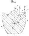
- an optical system for light emitting diodes comprises a carrier lens, indicated overall by 12, with a diode 13 incorporated in a fixed manner on the optical axis 14 within the carrier lens 12.
- a mirror 31 is positioned within the carrier lens 12 in such a manner that the light emitted by the diode 13 can be transmitted by the optical system only in a frontal direction.
- the carrier lens 12 consists of a front portion 18 with an outer transverse surface 25 formed concave towards the emitted light, and a longitudinal portion 19 for incorporating the diode 13 with the mirror 31.
- the longitudinal portion 19 is shaped such that its outer longitudinal surface 22 is concave towards the diode 13, in this case with its major diameter close to the front portion 18.
- the transverse surface 25 is surrounded by a further outer transverse surface 24 having a convex shape of spherical or ellipsoidal nature towards the light emitted in a longitudinal direction.
- the longitudinal portion 19 is able to reflect light rays emitted by the diode 13 via the concave longitudinal surface 22 towards the further outer transverse surface 24, which is able to transmit the light rays to the outside in a longitudinal direction.
- Figure 1 also shows a light ray 27 emitted by the diode 13 in a direction towards the outer transverse surface 25, at which it is refracted such that it leaves the carrier lens 12 in the longitudinal direction and hence parallel to the optical axis 14.
- the diode 13, together with the mirror 31, is able to emit light rays within a solid angle of 2 ⁇ about the optical axis 14, these being conveyed by the optical system formed by the surfaces 22, 24 and 25 into a beam of limited angular aperture.
- FIG. 2 shows an embodiment of the optical system according to the present invention, in which parts corresponding to the embodiment of Figure 1 are indicated by the same numerals.
- the carrier lens 12 consists of a plurality of lenses, namely an outer lens element 17, an inner lens 26 carrying the diode 13 with the mirror 31, and an intermediate lens 20.
- the outer lens element 17 has the same external configuration as the carrier lens 12 of the embodiment of Figure 1 and is provided internally with a cavity 21.
- the cavity 21 is bounded in a longitudinal direction by a front part 18 and in a direction perpendicular to the optical axis 14 by a longitudinal part 19.
- the cavity 21 is therefore open in a longitudinal direction in front of the front part 18 to allow the inner lens 26 to be inserted into the outer lens element 17.
- the inner lens 26 is integrated into the cavity 21 such that the intermediate lens 20 is positioned between the inner lens 26 and the lens element 17 and formed by in-situ polymerization of a suitable resin. In this manner the intermediate lens 20 fixes the inner lens 26 to the lens element 17 so that there are no gaps in the cavity 21.
- the inner lens 26 comprises in its front part a surface 15 concave towards the emitted light and at its longitudinal part a cylindrical or frusto-conical surface 16.
- the front part of the inner lens 26 is generally of hemispherical shape.
- the outer lens element 17 is shaped according to the present invention such that the front part 18 is in the form of the meniscus cup concave towards the emitted light.
- the longitudinal part 19 is shaped such that the cavity 21 is in the form of a cone frustum with its minor diameter towards the front part 18.
- Figure 2 also shows a light ray 29 emitted by the diode 13 and refracted at the two separation surfaces of the intermediate lens 20 in the direction of the outer transverse surface 25, at which it is refracted such that it emerges from the carrier lens 12 again in a longitudinal direction parallel to the optical axis 14,
- the lens element 17 is provided in the cavity 21 with a plurality of longitudinal guides 23, in this case three guides 23.
- the purpose of the guides 23, which on assembly are in contact with the outer diameter of the inner lens 26, is to position the inner lens 26 plus diode 13 in the cavity 21 such that the diode 13 is always on the optical axis 14.
- the carrier lens 12, the outer lens element 17, the intermediate lens 20 and the inner lens 26 are of injection-mouldable transparent polymer.
- the absolute refractive index of the intermediate lens 20 must be different from the absolute refractive index of the inner lens 26 and of the lens element 17.
- the absolute refractive index of the inner lens 26 is generally chosen by the manufacturer as high as possible (greater than 1.57) to improve the emissivity of the LED which has an index close to 3.
- the absolute refractive index of the intermediate lens 20 is between 1.33 and 1.48 and is preferably 1.415, and that of the lens element 17 is between 1.48 and 1.63, and is preferably 1.59.
- the complete optical system of the present invention is formed by firstly prefabricating the lens element 17 and the inner lens 26 with the diode 13 and mirror 31 incorporated.
- the inner lens 26 is then inserted into the cavity 21 of the lens element 17, in which the diode 13 is automatically positioned on the optical axis 14 because of the presence of the longitudinal guides 23.
- the free space remaining between the inner lens 26 and the lens element 17 is filled by pouring in a transparent thermosetting polymer, which forms the intermediate lens 20. In this manner the optical system 11 becomes a single piece by virtue of the intermediate lens 20.
- the improvement in the optical system according to the present invention is based on the fact that the longitudinal surface 22 and the transverse surface 24 of the longitudinal part 19 of the lens element 17 allow recovery of the light radiation which would otherwise be dispersed by the inability of the surface 16, for example cylindrical, of the inner lens 26 to produce adequate transmission.
- the optical system of the present invention is therefore a bifocal optical system, being structured such that the longitudinal part 19 has a focal point indicated by F2, which is different from that indicated by F1 of the front part 18.
- This focal difference is substantially equivalent to the error in the positioning of the diode 13 within the inner lens 26. It is noted that any reduction in the efficiency of the front part 18 caused by the LED positioning error is recovered by the longitudinal part 19, to increase the efficiency of the optical system, and vice versa. In this manner the achieved overall efficiency of the optical system is practically constant independently of the LED positioning error.
- the second embodiment of the optical system is therefore applied to existing commercial carrier lenses, which can have any absolute refractive index, and enables their performance to be considerably improved by levelling the varying degree of dispersion in commercial production. In this case the performance is improved on an average by a factor of between 1.5 and 4, depending on whether the initial intensity is high or low.
- a commercially existent carrier lens such as the inner lens 26 with the diode 13 and mirror 31 incorporated, is only effective for transmitting light rays to the outside in the longitudinal direction, these being emitted by the diode 13 in a bundle having an angular aperture of a maximum of 39° about the optical axis 14, as shown in Figure 4.
- the application of the optical system of the present invention enables light rays emitted by the diode 13 in a bundle having an angular aperture greater than 39°, for example 45° or more about the optical axis 14, to be transmitted to the outside in a longitudinal direction.
- the embodiment of Figure 2 has the further advantage that as the lens element of the present invention is of non-limiting form, the optical system can be easily applied to different types of light emitter device, for example the internal lens type, to always achieve a considerable improvement in the effective performance of the LED.
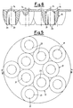
- Figures 3 to 6 show groups of lens elements 17, in which each group is formed as a single piece.
- Figures 3 and 4 show a group for example of five lens elements 17, whereas Figures 5 and 6 show a group of ten lens elements 17.
- the present invention is very suitable for example for use in variable-message road information panels and in motor vehicle indicators.
- the present invention is very effective, because if sunlight is present the light emitting diodes 13 must demonstrate maximum performance, which can be achieved only by the present optical system.
- Figure 7 shows a second embodiment of the outer lens element 17 with a flat transverse surface 24 and a paraboloid outer, longitudinal surface 22.
- Figure 8 shows a third embodiment of the outer lens element 17 with a transverse surface 24 of spherical or ellipsoidal rotation shape, the outer longitudinal surface 22 being ellipsoidal.
- the embodiment of the optical system according to the present invention therefore consists of two sub-systems, one being purely dioptric and the other being mixed dioptric-catoptric, in two different practical forms, one of which is homogeneous and to be used for incorporation of the LED 13 in the polymer,. and the other being additional employing more than one polymer, to be used to improve the performance of LED devices which are already commercially available.
- the outer longitudinal surface 22 can also be aluminized.
Landscapes
- Physics & Mathematics (AREA)
- General Physics & Mathematics (AREA)
- Optics & Photonics (AREA)
- Led Device Packages (AREA)
- Led Devices (AREA)
- Lenses (AREA)
- Facsimile Scanning Arrangements (AREA)
Claims (6)
- Système optique pour diodes électroluminescentes, dans lequel la diode (13) est incorporée, de façon fixe, sur l'axe optique (14) d'une lentille porteuse (12), cet axe optique (14) définissant une direction longitudinale, la lentille porteuse (12) étant constituée d'une partie avant (18), avec une surface transversale extérieure (25) formée de façon concave en direction de la lumière émise et, afin d'incorporer la diode (13), une partie longitudinale (19) avec une surface longitudinale extérieure (22), la surface longitudinale extérieure (22) présentant une forme concave en direction de la diode (13) et la surface transversale concave (25) étant entourée par une autre surface transversale extérieure (24), dans laquelle la surface longitudinale concave (22) est conçue pour réfléchir les rayons de lumière émis par la diode en direction de l'autre surface transversale extérieure (24), qui est conçue pour transmettre les rayons de lumière vers l'extérieur, dans une direction longitudinale, cette autre surface transversale extérieure (24) étant plate ou convexe, en direction de la lumière émise dans la direction longitudinale et entourant coaxialement la partie avant (18) de la lentille porteuse (12), la surface longitudinale extérieure (22) de la lentille porteuse (12) étant coaxiale à l'axe optique (14), caractérisé en ce que la lentille porteuse (12) est constituée d'un élément formant lentille extérieure (17), d'une lentille intérieure (26) portant la diode (13) et d'une lentille intermédiaire (20) , dans laquelle l'élément formant lentille extérieure (17) présente la configuration externe de la lentille porteuse (12) et présente, à l'intérieur, une cavité (21) délimitée, dans une direction longitudinale, par une partie avant (18) et, dans une direction perpendiculaire à l'axe optique (14), par une partie longitudinale (19), la lentille intérieure (26) étant intégrée dans la cavité (21) de telle sorte que la lentille intermédiaire (20) est positionnée entre la lentille intérieure (26) et l'élément formant lentille extérieure (17), et est conçue pour fixer la lentille intérieure (26) sur l'élément formant lentille extérieure (17) de telle sorte qu'il n'existe pas de vide dans la cavité (21), la cavité (21) de l'élément formant lentille extérieure (17) présentant une forme telle que la partie avant (18) ait la forme d'un ménisque concave en direction de la lumière émise et que la partie longitudinale (19) présente une forme telle que la cavité ait la forme d'un tronc de cône avec sa troncature orientée en direction de la partie avant (18), et la lentille intermédiaire (20) étant obtenue par polymérisation in-situ d'une résine thermodurcissable.
- Système optique selon la revendication 1, caractérisé en ce que l'autre surface transversale extérieure (24) est convexe et en ce que la forme convexe est de nature sphérique ou ellipsoïdale.
- Système optique selon la revendication 1, caractérisé en ce que l'indice de réfraction absolu de la lentille intermédiaire (20) est différent de l'indice de réfraction absolu de la lentille intérieure (26) et de l'élément formant lentille extérieure (17), l'indice de réfraction absolu de la lentille intermédiaire (20) étant compris entre 1,33 et 1,48, de préférence 1,415, et cet indice de réfraction absolu de l'élément formant lentille extérieure (17) étant compris entre 1,49 et 1,63, de préférence 1,59.
- Système optique selon la revendication 1, caractérisé en ce que la lentille intérieure (26) comprend, au niveau de sa partie avant, une surface (15) concave en direction de la lumière émise et, au niveau de sa partie longitudinale, une surface (16) de forme cylindrique ou tronconique.
- Système optique selon la revendication 1, caractérisé en ce que l'élément formant lentille extérieure (17) est prévu dans la cavité (21) avec une pluralité de guides longitudinaux (23) conçus pour positionner la lentille intérieure (26) à l'intérieur de la cavité (21) de telle sorte que la diode (13) soit positionnée sur l'axe optique (14).
- Système optique selon la revendication 1, caractérisé en ce que l'élément formant lentille extérieure (17) fait partie d'un groupe d'éléments formant lentilles extérieures (17) qui, ensemble, forment un élément unique.
Applications Claiming Priority (2)
| Application Number | Priority Date | Filing Date | Title |
|---|---|---|---|
| ITMI931654 | 1993-07-23 | ||
| IT93MI001654A IT1265106B1 (it) | 1993-07-23 | 1993-07-23 | Sistema ottico per diodi emettitori di luce |
Publications (3)
| Publication Number | Publication Date |
|---|---|
| EP0635744A2 EP0635744A2 (fr) | 1995-01-25 |
| EP0635744A3 EP0635744A3 (fr) | 1995-12-06 |
| EP0635744B1 true EP0635744B1 (fr) | 1999-04-21 |
Family
ID=11366679
Family Applications (1)
| Application Number | Title | Priority Date | Filing Date |
|---|---|---|---|
| EP93202869A Expired - Lifetime EP0635744B1 (fr) | 1993-07-23 | 1993-10-12 | Système optique pour des diodes électroluminescentes |
Country Status (7)
| Country | Link |
|---|---|
| US (1) | US5485317A (fr) |
| EP (1) | EP0635744B1 (fr) |
| JP (1) | JPH0758362A (fr) |
| AT (1) | ATE179257T1 (fr) |
| DE (1) | DE69324575T2 (fr) |
| ES (1) | ES2133353T3 (fr) |
| IT (1) | IT1265106B1 (fr) |
Families Citing this family (161)
| Publication number | Priority date | Publication date | Assignee | Title |
|---|---|---|---|---|
| US5699201A (en) * | 1995-03-27 | 1997-12-16 | Hewlett-Packard Co. | Low-profile, high-gain, wide-field-of-view, non-imaging optics |
| US6403124B1 (en) * | 1997-04-16 | 2002-06-11 | Sigma-Tau Industrie Farmaceutiche Riunite S.P.A. | Storage and maintenance of blood products including red blood cells and platelets |
| US5757557A (en) * | 1997-06-09 | 1998-05-26 | Tir Technologies, Inc. | Beam-forming lens with internal cavity that prevents front losses |
| JP3057432B2 (ja) * | 1997-08-26 | 2000-06-26 | スタンレー電気株式会社 | 受光素子用レンズ |
| US6200134B1 (en) | 1998-01-20 | 2001-03-13 | Kerr Corporation | Apparatus and method for curing materials with radiation |
| US6525386B1 (en) * | 1998-03-10 | 2003-02-25 | Masimo Corporation | Non-protruding optoelectronic lens |
| EP1045193A1 (fr) * | 1999-04-13 | 2000-10-18 | MCDERMOTT, Kevin F. | Dispositif d'éclairage concentrant la lumière axiale par un réflecteur convergeant incliné |
| KR100682563B1 (ko) * | 1999-07-26 | 2007-02-15 | 라보 스피아 가부시키가이샤 | 벌크형 렌즈, 발광체, 조명 기구 및 광 정보 시스템 |
| US6953340B2 (en) * | 1999-09-24 | 2005-10-11 | Cao Group, Inc. | Light for use in activating light-activated materials, the light having a detachable light module containing a heat sink and a semiconductor chip |
| US6971875B2 (en) | 1999-09-24 | 2005-12-06 | Cao Group, Inc. | Dental curing light |
| US7077648B2 (en) * | 1999-09-24 | 2006-07-18 | Cao Group, Inc. | Curing light |
| US6988891B2 (en) * | 1999-09-24 | 2006-01-24 | Cao Group, Inc. | Curing light |
| US6926524B2 (en) * | 1999-09-24 | 2005-08-09 | Cao Group, Inc. | Curing light |
| US6929472B2 (en) | 1999-09-24 | 2005-08-16 | Cao Group, Inc. | Curing light |
| US6988890B2 (en) | 1999-09-24 | 2006-01-24 | Cao Group, Inc. | Curing light |
| US6979193B2 (en) | 1999-09-24 | 2005-12-27 | Cao Group, Inc. | Curing light |
| US7066732B2 (en) * | 1999-09-24 | 2006-06-27 | Cao Group, Inc. | Method for curing light-curable materials |
| US6971876B2 (en) | 1999-09-24 | 2005-12-06 | Cao Group, Inc. | Curing light |
| US6719559B2 (en) | 1999-09-24 | 2004-04-13 | Densen Cao | Curing light |
| US6719558B2 (en) | 1999-09-24 | 2004-04-13 | Densen Cao | Curing light |
| US6910886B2 (en) | 1999-09-24 | 2005-06-28 | Cao Group, Inc. | Curing light |
| US7294364B2 (en) * | 1999-09-24 | 2007-11-13 | Cao Group, Inc. | Method for curing composite materials |
| US6981867B2 (en) | 1999-09-24 | 2006-01-03 | Cao Group, Inc. | Curing light |
| US6755649B2 (en) | 1999-09-24 | 2004-06-29 | Cao Group, Inc. | Curing light |
| US6932600B2 (en) * | 1999-09-24 | 2005-08-23 | Cao Group, Inc. | Curing light |
| US6824294B2 (en) * | 1999-09-24 | 2004-11-30 | Cao Group, Inc. | Light for use in activating light-activated materials, the light having a plurality of chips mounted in a gross well of a heat sink, and a dome covering the chips |
| US6755648B2 (en) | 1999-09-24 | 2004-06-29 | Cao Group, Inc. | Curing light |
| US6780010B2 (en) | 1999-09-24 | 2004-08-24 | Cao Group, Inc. | Curing light |
| US6974319B2 (en) * | 1999-09-24 | 2005-12-13 | Cao Group, Inc. | Curing light |
| WO2001080635A1 (fr) * | 2000-04-21 | 2001-11-01 | Labosphere Institute | Dispositif menaçant |
| US6543911B1 (en) | 2000-05-08 | 2003-04-08 | Farlight Llc | Highly efficient luminaire having optical transformer providing precalculated angular intensity distribution and method therefore |
| US8360615B2 (en) | 2000-05-08 | 2013-01-29 | Farlight, Llc | LED light module for omnidirectional luminaire |
| DE10023353A1 (de) * | 2000-05-12 | 2001-11-29 | Osram Opto Semiconductors Gmbh | Optoelektronisches Bauelement und Verfahren zur Herstellung |
| US20020085390A1 (en) * | 2000-07-14 | 2002-07-04 | Hironobu Kiyomoto | Optical device and apparatus employing the same |
| SG100618A1 (en) * | 2001-01-03 | 2003-12-26 | Labosphere Inst | Bulky lens, light emitting unit, and lighting instrument |
| JP4344978B2 (ja) * | 2001-01-30 | 2009-10-14 | ラボ・スフィア株式会社 | 室内照明装置 |
| US6799967B2 (en) | 2001-07-10 | 2004-10-05 | Cao Group, Inc. | Light for use in activating light-activated materials, the light having a plurality of light emitting single chip arrays |
| US7108504B2 (en) | 2001-07-10 | 2006-09-19 | Cao Group, Inc. | Light for use in activating light-activated materials, the light having insulators and an air jacket |
| WO2003026031A1 (fr) * | 2001-09-11 | 2003-03-27 | Bridgestone Corporation | Element condensateur et procede de production de ce dernier, lampe a del comprenant un element condensateur et dispositif emettant de la lumiere lineaire comprenant une lampe del en tant que source de lumiere |
| US6538828B1 (en) * | 2001-10-24 | 2003-03-25 | Seamus Redmond | Magnifying page illuminator |
| AU2002365761A1 (en) * | 2001-11-16 | 2003-06-17 | Toyoda Gosei Co., Ltd. | Light-emitting diode, led light, and light apparatus |
| JP2003158302A (ja) * | 2001-11-21 | 2003-05-30 | Toyoda Gosei Co Ltd | 発光ダイオード |
| ITMI20012579A1 (it) * | 2001-12-06 | 2003-06-06 | Fraen Corp Srl | Modulo illuminante ad elevata dissipazione di calore |
| US6560038B1 (en) * | 2001-12-10 | 2003-05-06 | Teledyne Lighting And Display Products, Inc. | Light extraction from LEDs with light pipes |
| DE10163116B4 (de) * | 2001-12-24 | 2008-04-10 | G.L.I. Global Light Industries Gmbh | Verfahren zum Herstellen von lichtleitenden LED-Körpern in zwei räumlich und zeitlich getrennten Stufen |
| DE10163117C5 (de) | 2001-12-24 | 2005-12-01 | G.L.I. Global Light Industries Gmbh | Verfahren zum Herstellen von lichtleitenden LED-Körpern in zwei zeitlich getrennten Stufen |
| US20030148242A1 (en) * | 2002-02-05 | 2003-08-07 | Fischer Dan E. | Lightweight hand held dental curing device |
| US6940659B2 (en) * | 2002-01-11 | 2005-09-06 | Ultradent Products, Inc. | Cone-shaped lens having increased forward light intensity and kits incorporating such lenses |
| US20030215766A1 (en) * | 2002-01-11 | 2003-11-20 | Ultradent Products, Inc. | Light emitting systems and kits that include a light emitting device and one or more removable lenses |
| US7106523B2 (en) | 2002-01-11 | 2006-09-12 | Ultradent Products, Inc. | Optical lens used to focus led light |
| JP4058291B2 (ja) * | 2002-04-10 | 2008-03-05 | 富士通株式会社 | 表示装置及び電子機器 |
| JP3996164B2 (ja) * | 2002-05-17 | 2007-10-24 | シーシーエス株式会社 | 発光ダイオード装置及び発光ダイオード装置の製造方法 |
| US6826336B2 (en) * | 2002-05-22 | 2004-11-30 | The Boeing Company | Fiber optic LED illuminator |
| US20030230377A1 (en) * | 2002-06-14 | 2003-12-18 | Turvey Robert R. | Apparatus and method for automated splicing of closer tape |
| US6827475B2 (en) * | 2002-09-09 | 2004-12-07 | Steven Robert Vetorino | LED light collection and uniform transmission system |
| DE60317808T2 (de) * | 2002-09-30 | 2008-10-30 | Teledyne Lighting and Display Products, Inc., Los Angeles | Beleuchtungsanordnung |
| US6724543B1 (en) | 2002-10-23 | 2004-04-20 | Visteon Global Technologies, Inc. | Light collection assembly having mixed conic shapes for use with various light emitting sources |
| AU2003280708A1 (en) * | 2002-11-05 | 2004-06-07 | Matsushita Electric Industrial Co., Ltd. | Light-emitting diode |
| JP4040955B2 (ja) * | 2002-11-06 | 2008-01-30 | 株式会社小糸製作所 | 車両用前照灯及びその製造方法 |
| US20040101802A1 (en) * | 2002-11-21 | 2004-05-27 | Scott Robert R. | Wide bandwidth led curing light |
| AU2003299568B2 (en) * | 2002-11-27 | 2010-07-22 | Ampio Pharmaceuticals, Inc. | Treatment of diseases and conditions mediated by increased phosphorylation |
| US6994546B2 (en) * | 2002-12-18 | 2006-02-07 | Ultradent Products, Inc. | Light curing device with detachable power supply |
| US6890175B2 (en) * | 2002-12-18 | 2005-05-10 | Ultradent Products, Inc. | Cooling system for hand-held curing light |
| US6939059B1 (en) * | 2003-01-03 | 2005-09-06 | Finisar Corporation | Method and system for optical packaging |
| US20040257577A1 (en) | 2003-01-27 | 2004-12-23 | Zetetic Institute | Apparatus and method for joint measurements of conjugated quadratures of fields of reflected/scattered and transmitted beams by an object in interferometry |
| US7084983B2 (en) * | 2003-01-27 | 2006-08-01 | Zetetic Institute | Interferometric confocal microscopy incorporating a pinhole array beam-splitter |
| KR20050098268A (ko) * | 2003-01-27 | 2005-10-11 | 제테틱 인스티튜트 | 트렌치의 특성을 측정하는 간섭 공초점 현미경에 사용되는누설 유도파 모드 |
| JP2006516766A (ja) * | 2003-02-04 | 2006-07-06 | ゼテテック インスティテュート | 非共焦点、共焦点、および、干渉型共焦点顕微鏡観察で生じる基板−媒体界面における屈折率ミスマッチ作用の補償 |
| WO2004072688A2 (fr) * | 2003-02-07 | 2004-08-26 | Zetetic Institute | Reseau de sources multiples alimente par des structures d'ondes guidees, et cavites resonantes a structures d'ondes guidees - |
| KR20050101335A (ko) * | 2003-02-13 | 2005-10-21 | 제테틱 인스티튜트 | 가로 미분 간섭계 공초점 현미경 |
| USD529613S1 (en) | 2003-02-18 | 2006-10-03 | Ultradent Products, Inc. | Dental illumination device |
| USD530013S1 (en) | 2003-02-18 | 2006-10-10 | Ultradent Products, Inc. | Dental illumination device |
| EP1595108A4 (fr) * | 2003-02-19 | 2007-01-24 | Zetetic Inst | Microscopie confocale interferometrique differentielle longitudinale |
| JP2006518488A (ja) * | 2003-02-19 | 2006-08-10 | ゼテテック インスティテュート | 暗視野干渉共焦点顕微鏡使用の方法及び装置 |
| KR20050119672A (ko) * | 2003-04-01 | 2005-12-21 | 제테틱 인스티튜트 | 간섭계 내에서 물체에 의해 산란/반사 또는 투과된 직교편광 빔의 필드의 결합 측정을 위한 장치 및 방법 |
| KR20050108422A (ko) | 2003-04-01 | 2005-11-16 | 제테틱 인스티튜트 | 반사굴절 렌즈 시스템을 제조하는 방법 |
| KR20050119680A (ko) * | 2003-04-03 | 2005-12-21 | 제테틱 인스티튜트 | 간섭계에서 피사체에 의해 후방 산란 및 전방 산란/반사된빔의 필드의 측정을 위한 장치 및 방법 |
| US20070020578A1 (en) * | 2005-07-19 | 2007-01-25 | Scott Robert R | Dental curing light having a short wavelength LED and a fluorescing lens for converting wavelength light to curing wavelengths and related method |
| US20040214131A1 (en) * | 2003-04-25 | 2004-10-28 | Ultradent Products, Inc., | Spot curing lens used to spot cure a dental appliance adhesive and systems and methods employing such lenses |
| US7084984B2 (en) | 2003-07-07 | 2006-08-01 | Zetetic Institute | Apparatus and method for high speed scan for detection and measurement of properties of sub-wavelength defects and artifacts in semiconductor and mask metrology |
| WO2005008214A2 (fr) * | 2003-07-07 | 2005-01-27 | Zetetic Institute | Appareil et procede permettant d'effectuer des mesures ellipsometriques avec une resolution spatiale elevee |
| US7192276B2 (en) * | 2003-08-20 | 2007-03-20 | Ultradent Products, Inc. | Dental curing light adapted to emit light at a desired angle |
| DE10340039B4 (de) | 2003-08-28 | 2011-01-05 | Odelo Gmbh | Beleuchtungseinheit mit Lichtquelle und dieser nachgeschaltetem transparentem Lichtleitkörper |
| TW200523578A (en) * | 2003-09-10 | 2005-07-16 | Zetetic Inst | Catoptric and catadioptric imaging systems with adaptive catoptric surfaces |
| WO2005031397A2 (fr) * | 2003-09-26 | 2005-04-07 | Zetetic Institute | Systemes d'imagerie catoptriques et catadioptriques a diviseurs de faisceaux a pellicule et matrice d'orifices et surfaces catoptriques non-adaptatives et adaptatives |
| US6819506B1 (en) | 2003-09-30 | 2004-11-16 | Infinity Trading Co. Ltd. | Optical lens system for projecting light in a lambertion pattern from a high power led light source |
| JP2005109289A (ja) * | 2003-10-01 | 2005-04-21 | Nichia Chem Ind Ltd | 発光装置 |
| WO2005033747A2 (fr) * | 2003-10-01 | 2005-04-14 | Zetetic Institute | Procede et appareil permettant d'ameliorer la resolution de composants d'images a haute frequence spatiale a l'aide de faisceaux d'ondes stationnaires, en microscopie non interferometrique et interferometrique |
| US7083297B2 (en) * | 2003-12-09 | 2006-08-01 | Surefire Llc | Flashlight with lens for transmitting central and off-axis light sources |
| US7144250B2 (en) | 2003-12-17 | 2006-12-05 | Ultradent Products, Inc. | Rechargeable dental curing light |
| US7195482B2 (en) * | 2003-12-30 | 2007-03-27 | Ultradent Products, Inc. | Dental curing device having a heat sink for dissipating heat |
| US7074040B2 (en) * | 2004-03-30 | 2006-07-11 | Ultradent Products, Inc. | Ball lens for use with a dental curing light |
| JP2005322380A (ja) * | 2004-04-09 | 2005-11-17 | Toshiba Corp | 半導体記憶装置 |
| TW200538703A (en) * | 2004-05-06 | 2005-12-01 | Zetetic Inst | Apparatus and methods for measurement of critical dimensions of features and detection of defects in UV, VUV, and EUV lithography masks |
| WO2005114095A2 (fr) * | 2004-05-21 | 2005-12-01 | Zetetic Institute | Appareils et procedes de mesure de recouvrements, de marques d'alignement et de dimensions critiques faisant appel a l'interferometrie optique |
| DE102004042561A1 (de) * | 2004-07-20 | 2006-02-16 | Osram Opto Semiconductors Gmbh | Optisches Element |
| US7161680B2 (en) * | 2004-08-16 | 2007-01-09 | Zetetic Institute | Apparatus and method for joint and time delayed measurements of components of conjugated quadratures of fields of reflected/scattered and transmitted/scattered beams by an object in interferometry |
| WO2006023612A2 (fr) * | 2004-08-19 | 2006-03-02 | Zetetic Institute | Revetement sub-nanometrique, dimension critique, et systemes de metrologie optique a projection d'outils lithographiques bases sur la mesure de changements induits sur la tranche par l'exposition dans la photoresine |
| US7145663B2 (en) * | 2004-09-20 | 2006-12-05 | Zetetic Institute | Catoptric imaging systems comprising pellicle and/or aperture-array beam-splitters and non-adaptive and/or adaptive catoptric surfaces |
| DE102004045950A1 (de) | 2004-09-22 | 2006-03-30 | Osram Opto Semiconductors Gmbh | Gehäuse für ein optoelektronisches Bauelement, optoelektronisches Bauelement und Verfahren zur Herstellung eines optoelektronischen Bauelements |
| KR101080355B1 (ko) | 2004-10-18 | 2011-11-04 | 삼성전자주식회사 | 발광다이오드와 그 렌즈 |
| US7056116B2 (en) * | 2004-10-26 | 2006-06-06 | Ultradent Products, Inc. | Heat sink for dental curing light comprising a plurality of different materials |
| USRE43464E1 (en) | 2004-12-29 | 2012-06-12 | University Of Florida Research Foundation, Incorporated | High intensity laser or diode-based lighting apparatus having integrated optics |
| US7731395B2 (en) * | 2005-01-26 | 2010-06-08 | Anthony International | Linear lenses for LEDs |
| CN100585268C (zh) * | 2005-03-07 | 2010-01-27 | 日亚化学工业株式会社 | 面状照射光源及面状照射装置 |
| KR101112552B1 (ko) | 2005-03-08 | 2012-02-15 | 삼성전자주식회사 | 발광 다이오드용 렌즈, 발광 다이오드, 이를 포함하는 백라이트 어셈블리 및 액정 표시 장치 |
| KR101136344B1 (ko) * | 2005-04-06 | 2012-04-18 | 삼성전자주식회사 | 광학 렌즈, 이를 갖는 광학 모듈, 이를 갖는 백라이트어셈블리 및 이를 갖는 표시 장치 |
| KR101229874B1 (ko) * | 2005-04-22 | 2013-02-05 | 삼성디스플레이 주식회사 | 광학 렌즈와, 이를 갖는 광학 패키지, 백라이트 어셈블리및 표시장치 |
| CN101238325B (zh) | 2005-06-01 | 2011-03-30 | Ccs株式会社 | 光照射装置 |
| US20070037113A1 (en) * | 2005-08-10 | 2007-02-15 | Scott Robert R | Dental curing light including a light integrator for providing substantially equal distribution of each emitted wavelength |
| US7401948B2 (en) * | 2005-10-17 | 2008-07-22 | Visteon Global Technologies, Inc. | Near field lens having reduced size |
| US7160010B1 (en) | 2005-11-15 | 2007-01-09 | Visteon Global Technologies, Inc. | Light manifold for automotive light module |
| US7489453B2 (en) * | 2005-11-15 | 2009-02-10 | Visteon Global Technologies, Inc. | Side emitting near field lens |
| US7564070B2 (en) * | 2005-11-23 | 2009-07-21 | Visteon Global Technologies, Inc. | Light emitting diode device having a shield and/or filter |
| US7438454B2 (en) * | 2005-11-29 | 2008-10-21 | Visteon Global Technologies, Inc. | Light assembly for automotive lighting applications |
| US20070128577A1 (en) * | 2005-12-05 | 2007-06-07 | Ultradent Products, Inc. | Dental curing lights including a capacitor power source |
| JP2007173322A (ja) * | 2005-12-19 | 2007-07-05 | Enplas Corp | 発光装置 |
| JP4965858B2 (ja) * | 2005-12-26 | 2012-07-04 | 株式会社東芝 | レンズ付発光ダイオード装置 |
| US8044412B2 (en) | 2006-01-20 | 2011-10-25 | Taiwan Semiconductor Manufacturing Company, Ltd | Package for a light emitting element |
| JP2007265688A (ja) * | 2006-03-27 | 2007-10-11 | Harison Toshiba Lighting Corp | コリメーションレンズ及びこれを用いた照明装置 |
| US8044585B2 (en) * | 2006-05-02 | 2011-10-25 | Chain Technology Consultant Inc. | Light emitting diode with bumps |
| US7804147B2 (en) * | 2006-07-31 | 2010-09-28 | Cree, Inc. | Light emitting diode package element with internal meniscus for bubble free lens placement |
| US20080030974A1 (en) * | 2006-08-02 | 2008-02-07 | Abu-Ageel Nayef M | LED-Based Illumination System |
| CN101523253B (zh) | 2006-09-29 | 2012-12-12 | 奥斯兰姆奥普托半导体有限责任公司 | 光学光导体和光学装置 |
| US8840277B1 (en) | 2007-01-09 | 2014-09-23 | Surefire, Llc | Light assembly for flashlights |
| US8007156B1 (en) | 2007-01-09 | 2011-08-30 | Surefire, Llc | Light assembly for flashlights |
| US8727576B1 (en) | 2007-01-09 | 2014-05-20 | Surefire, Llc | Light assembly for flashlights |
| US8714782B1 (en) | 2007-01-09 | 2014-05-06 | Surefire, Llc | Light assembly for flashlights |
| US8033690B1 (en) | 2007-01-09 | 2011-10-11 | Surefire, Llc | Light assembly for flashlights |
| DE102007008405B4 (de) * | 2007-02-21 | 2011-11-17 | Automotive Lighting Reutlingen Gmbh | Kraftfahrzeugleuchte |
| CN100492133C (zh) * | 2007-02-25 | 2009-05-27 | 友达光电股份有限公司 | 具聚光效果的光源装置以及使用此光源装置的背光模块 |
| EP2135005B1 (fr) * | 2007-04-05 | 2010-10-06 | Koninklijke Philips Electronics N.V. | Dispositif de mise en forme de faisceaux lumineux |
| US7554742B2 (en) * | 2007-04-17 | 2009-06-30 | Visteon Global Technologies, Inc. | Lens assembly |
| US7618160B2 (en) * | 2007-05-23 | 2009-11-17 | Visteon Global Technologies, Inc. | Near field lens |
| US8002435B2 (en) * | 2008-06-13 | 2011-08-23 | Philips Electronics Ltd Philips Electronique Ltee | Orientable lens for an LED fixture |
| US7766509B1 (en) | 2008-06-13 | 2010-08-03 | Lumec Inc. | Orientable lens for an LED fixture |
| US8235556B2 (en) * | 2008-10-20 | 2012-08-07 | Reflexite Corporation | Condensing element, array, and methods thereof |
| JP5228807B2 (ja) * | 2008-11-04 | 2013-07-03 | 豊田合成株式会社 | 発光ダイオードの光放射方法 |
| WO2010090862A2 (fr) * | 2009-01-21 | 2010-08-12 | Abu-Ageel Nayef M | Système d'éclairage utilisant des matériaux de conversion de longueur d'onde et le recyclage de lumière |
| US8246212B2 (en) * | 2009-01-30 | 2012-08-21 | Koninklijke Philips Electronics N.V. | LED optical assembly |
| JP5465452B2 (ja) * | 2009-03-26 | 2014-04-09 | 株式会社キーエンス | 光ファイバ型光電センサの本体ユニット及び光ファイバ型光電センサ |
| US9066777B2 (en) | 2009-04-02 | 2015-06-30 | Kerr Corporation | Curing light device |
| US9072572B2 (en) | 2009-04-02 | 2015-07-07 | Kerr Corporation | Dental light device |
| US10422503B2 (en) * | 2009-10-30 | 2019-09-24 | Ideal Industries Lighting Llc | One-piece multi-lens optical member and method of manufacture |
| USD638944S1 (en) | 2009-09-22 | 2011-05-31 | Ultradent Products, Inc. | Dental illumination device |
| ES2363396B1 (es) * | 2010-01-20 | 2012-08-30 | Universidad Complutense De Madrid | Sistema optico de colimacion o concentracion de radiacion luminosa |
| JP2011198473A (ja) * | 2010-03-17 | 2011-10-06 | Igari Industry Co Ltd | 集光光学素子及びそれを用いた装置 |
| TWI452360B (zh) | 2010-12-10 | 2014-09-11 | Ind Tech Res Inst | 準直光學元件、準直光學組件、準直光學陣列及準直光學模組 |
| US8351125B2 (en) * | 2010-12-10 | 2013-01-08 | Industrial Technology Research Institute | Directional light distributed optical element and directional light distributed optical assembly |
| DE102011085291B4 (de) | 2011-07-08 | 2021-02-25 | Zumtobel Lighting Gmbh | Lichtbeeinflussungselement zur Beeinflussung der Lichtabgabe von im Wesentlichen punktförmigen Lichtquellen |
| DE102011079404A1 (de) | 2011-07-19 | 2013-01-24 | Zumtobel Lighting Gmbh | Anordnung zur Lichtabgabe |
| JP2013183078A (ja) * | 2012-03-02 | 2013-09-12 | Asahi Rubber Inc | レンズ付きled装置及び多方向照明装置 |
| US8969784B2 (en) | 2012-05-14 | 2015-03-03 | Avago Technologies General Ip (Singapore) Pte. Ltd. | Optical lens assembly and optical devices thereof |
| DE102012107676B4 (de) * | 2012-08-21 | 2016-04-14 | Truck-Lite Europe Gmbh | Optikkörper für eine Fahrzeugleuchte |
| US10400984B2 (en) | 2013-03-15 | 2019-09-03 | Cree, Inc. | LED light fixture and unitary optic member therefor |
| TWI585340B (zh) * | 2014-04-16 | 2017-06-01 | 鴻海精密工業股份有限公司 | 點光源的擴散鏡片 |
| US9470394B2 (en) | 2014-11-24 | 2016-10-18 | Cree, Inc. | LED light fixture including optical member with in-situ-formed gasket and method of manufacture |
| CN204785815U (zh) * | 2015-07-16 | 2015-11-18 | 泉州钰乘礼品有限公司 | 新型发光盆 |
| US9977235B2 (en) | 2016-06-21 | 2018-05-22 | Abl Ip Holding Llc | Variable total internal reflection electrowetting lens assembly for a detector |
| US10072822B2 (en) * | 2016-06-21 | 2018-09-11 | Abl Ip Holding Llc | Variable total internal reflection electrowetting lens assembly |
| US10247935B2 (en) | 2016-07-06 | 2019-04-02 | Abl Ip Holding Llc | MicroLED with integrated controllable beam steering and/or shaping |
Family Cites Families (8)
| Publication number | Priority date | Publication date | Assignee | Title |
|---|---|---|---|---|
| US2254961A (en) * | 1937-08-21 | 1941-09-02 | George M Cressaty | Unitary lens system |
| US2215900A (en) * | 1939-10-28 | 1940-09-24 | Ralph E Bitner | Catadioptrical lens |
| US2224178A (en) * | 1940-05-08 | 1940-12-10 | Ralph E Bitner | Catadioptrical lens system |
| SE385419B (sv) * | 1974-03-22 | 1976-06-28 | Asea Ab | Lysdiodanordning for utsendande av stralning i en forutbestemd riktning |
| US4698730A (en) * | 1986-08-01 | 1987-10-06 | Stanley Electric Co., Ltd. | Light-emitting diode |
| US4770514A (en) * | 1986-11-21 | 1988-09-13 | David Silverglate | Collimating compound catoptric immersion lens |
| US4935665A (en) * | 1987-12-24 | 1990-06-19 | Mitsubishi Cable Industries Ltd. | Light emitting diode lamp |
| US5173810A (en) * | 1991-08-21 | 1992-12-22 | Aisens Co., Ltd. | Light transmitting lens for use with a photoelectric sensor |
-
1993
- 1993-07-23 IT IT93MI001654A patent/IT1265106B1/it active IP Right Grant
- 1993-10-08 US US08/134,295 patent/US5485317A/en not_active Expired - Fee Related
- 1993-10-12 AT AT93202869T patent/ATE179257T1/de not_active IP Right Cessation
- 1993-10-12 EP EP93202869A patent/EP0635744B1/fr not_active Expired - Lifetime
- 1993-10-12 ES ES93202869T patent/ES2133353T3/es not_active Expired - Lifetime
- 1993-10-12 DE DE69324575T patent/DE69324575T2/de not_active Expired - Fee Related
- 1993-10-12 JP JP5277324A patent/JPH0758362A/ja active Pending
Also Published As
| Publication number | Publication date |
|---|---|
| US5485317A (en) | 1996-01-16 |
| IT1265106B1 (it) | 1996-10-30 |
| ITMI931654A0 (it) | 1993-07-23 |
| JPH0758362A (ja) | 1995-03-03 |
| EP0635744A3 (fr) | 1995-12-06 |
| ES2133353T3 (es) | 1999-09-16 |
| DE69324575T2 (de) | 1999-11-18 |
| ATE179257T1 (de) | 1999-05-15 |
| DE69324575D1 (de) | 1999-05-27 |
| EP0635744A2 (fr) | 1995-01-25 |
| ITMI931654A1 (it) | 1995-01-23 |
Similar Documents
| Publication | Publication Date | Title |
|---|---|---|
| EP0635744B1 (fr) | Système optique pour des diodes électroluminescentes | |
| US4770514A (en) | Collimating compound catoptric immersion lens | |
| US6986594B2 (en) | Lighting device for motor vehicles | |
| US4698730A (en) | Light-emitting diode | |
| CN1900579B (zh) | 特别用于机动车的照明或指示设备 | |
| EP1255306B1 (fr) | DEL à émission latérale | |
| US7431480B2 (en) | Optical element, compound optical element, and illuminating apparatus | |
| US5825051A (en) | Optoelectronic component with central hollow | |
| EP0940625B1 (fr) | Elément optique en forme de manifold bosselé pour système d' éclairage de véhicule | |
| US6607286B2 (en) | Lens and lens cap with sawtooth portion for light emitting diode | |
| US4257672A (en) | Optical coupler for connecting a light source to an optical transmission line | |
| US5697690A (en) | Illuminating device for vehicles | |
| JPH0983018A (ja) | 発光ダイオードユニット | |
| US12535667B2 (en) | Total internal reflection lens to improve color mixing of an LED light source | |
| KR20000071235A (ko) | 광송수신 모듈 | |
| KR20200110215A (ko) | 콜렉터의 허상 피조면을 이미지화하는 발광 장치 | |
| JP2004514918A (ja) | 特に自動車に用いられるレインセンサ | |
| JP3916668B2 (ja) | 窓ガラスの濡れ検出装置 | |
| JP2007171427A (ja) | 光モジュール及びこれを備えた光コネクタ | |
| JP4330716B2 (ja) | 投光装置 | |
| JPS6338272A (ja) | 光半導体装置 | |
| CN210775833U (zh) | 共用光路的主动光学系统、激光雷达、智能车或无人机 | |
| US20220196891A1 (en) | Combined Collimation and Diffuser Lens for Flood Illuminator | |
| US20040114880A1 (en) | Device for coupling light into an optical conductor | |
| US12486975B2 (en) | Lens structure and light source device having lens with half-mirror, and light receiver |
Legal Events
| Date | Code | Title | Description |
|---|---|---|---|
| PUAI | Public reference made under article 153(3) epc to a published international application that has entered the european phase |
Free format text: ORIGINAL CODE: 0009012 |
|
| AK | Designated contracting states |
Kind code of ref document: A2 Designated state(s): AT BE CH DE DK ES FR GB GR IE LI LU MC NL PT SE |
|
| PUAL | Search report despatched |
Free format text: ORIGINAL CODE: 0009013 |
|
| AK | Designated contracting states |
Kind code of ref document: A3 Designated state(s): AT BE CH DE DK ES FR GB GR IE LI LU MC NL PT SE |
|
| 17P | Request for examination filed |
Effective date: 19960416 |
|
| 17Q | First examination report despatched |
Effective date: 19970506 |
|
| GRAG | Despatch of communication of intention to grant |
Free format text: ORIGINAL CODE: EPIDOS AGRA |
|
| GRAG | Despatch of communication of intention to grant |
Free format text: ORIGINAL CODE: EPIDOS AGRA |
|
| GRAH | Despatch of communication of intention to grant a patent |
Free format text: ORIGINAL CODE: EPIDOS IGRA |
|
| GRAH | Despatch of communication of intention to grant a patent |
Free format text: ORIGINAL CODE: EPIDOS IGRA |
|
| GRAA | (expected) grant |
Free format text: ORIGINAL CODE: 0009210 |
|
| AK | Designated contracting states |
Kind code of ref document: B1 Designated state(s): AT BE CH DE DK ES FR GB GR IE LI LU MC NL PT SE |
|
| PG25 | Lapsed in a contracting state [announced via postgrant information from national office to epo] |
Ref country code: SE Free format text: THE PATENT HAS BEEN ANNULLED BY A DECISION OF A NATIONAL AUTHORITY Effective date: 19990421 Ref country code: NL Free format text: LAPSE BECAUSE OF FAILURE TO SUBMIT A TRANSLATION OF THE DESCRIPTION OR TO PAY THE FEE WITHIN THE PRESCRIBED TIME-LIMIT Effective date: 19990421 Ref country code: LI Free format text: LAPSE BECAUSE OF FAILURE TO SUBMIT A TRANSLATION OF THE DESCRIPTION OR TO PAY THE FEE WITHIN THE PRESCRIBED TIME-LIMIT Effective date: 19990421 Ref country code: GR Free format text: LAPSE BECAUSE OF NON-PAYMENT OF DUE FEES Effective date: 19990421 Ref country code: CH Free format text: LAPSE BECAUSE OF FAILURE TO SUBMIT A TRANSLATION OF THE DESCRIPTION OR TO PAY THE FEE WITHIN THE PRESCRIBED TIME-LIMIT Effective date: 19990421 Ref country code: BE Free format text: LAPSE BECAUSE OF FAILURE TO SUBMIT A TRANSLATION OF THE DESCRIPTION OR TO PAY THE FEE WITHIN THE PRESCRIBED TIME-LIMIT Effective date: 19990421 Ref country code: AT Free format text: LAPSE BECAUSE OF FAILURE TO SUBMIT A TRANSLATION OF THE DESCRIPTION OR TO PAY THE FEE WITHIN THE PRESCRIBED TIME-LIMIT Effective date: 19990421 |
|
| REF | Corresponds to: |
Ref document number: 179257 Country of ref document: AT Date of ref document: 19990515 Kind code of ref document: T |
|
| REG | Reference to a national code |
Ref country code: CH Ref legal event code: EP |
|
| REG | Reference to a national code |
Ref country code: IE Ref legal event code: FG4D |
|
| REF | Corresponds to: |
Ref document number: 69324575 Country of ref document: DE Date of ref document: 19990527 |
|
| PG25 | Lapsed in a contracting state [announced via postgrant information from national office to epo] |
Ref country code: DK Free format text: LAPSE BECAUSE OF FAILURE TO SUBMIT A TRANSLATION OF THE DESCRIPTION OR TO PAY THE FEE WITHIN THE PRESCRIBED TIME-LIMIT Effective date: 19990721 |
|
| PG25 | Lapsed in a contracting state [announced via postgrant information from national office to epo] |
Ref country code: PT Free format text: LAPSE BECAUSE OF FAILURE TO SUBMIT A TRANSLATION OF THE DESCRIPTION OR TO PAY THE FEE WITHIN THE PRESCRIBED TIME-LIMIT Effective date: 19990723 |
|
| ET | Fr: translation filed | ||
| REG | Reference to a national code |
Ref country code: ES Ref legal event code: FG2A Ref document number: 2133353 Country of ref document: ES Kind code of ref document: T3 |
|
| PG25 | Lapsed in a contracting state [announced via postgrant information from national office to epo] |
Ref country code: LU Free format text: LAPSE BECAUSE OF NON-PAYMENT OF DUE FEES Effective date: 19991012 Ref country code: IE Free format text: LAPSE BECAUSE OF NON-PAYMENT OF DUE FEES Effective date: 19991012 |
|
| REG | Reference to a national code |
Ref country code: CH Ref legal event code: PL |
|
| PLBE | No opposition filed within time limit |
Free format text: ORIGINAL CODE: 0009261 |
|
| 26N | No opposition filed | ||
| PG25 | Lapsed in a contracting state [announced via postgrant information from national office to epo] |
Ref country code: MC Free format text: LAPSE BECAUSE OF NON-PAYMENT OF DUE FEES Effective date: 20000430 |
|
| REG | Reference to a national code |
Ref country code: IE Ref legal event code: MM4A |
|
| PGFP | Annual fee paid to national office [announced via postgrant information from national office to epo] |
Ref country code: DE Payment date: 20001002 Year of fee payment: 8 |
|
| PGFP | Annual fee paid to national office [announced via postgrant information from national office to epo] |
Ref country code: FR Payment date: 20001010 Year of fee payment: 8 |
|
| PGFP | Annual fee paid to national office [announced via postgrant information from national office to epo] |
Ref country code: GB Payment date: 20001011 Year of fee payment: 8 |
|
| PGFP | Annual fee paid to national office [announced via postgrant information from national office to epo] |
Ref country code: ES Payment date: 20001025 Year of fee payment: 8 |
|
| PG25 | Lapsed in a contracting state [announced via postgrant information from national office to epo] |
Ref country code: GB Free format text: LAPSE BECAUSE OF NON-PAYMENT OF DUE FEES Effective date: 20011012 |
|
| PG25 | Lapsed in a contracting state [announced via postgrant information from national office to epo] |
Ref country code: ES Free format text: LAPSE BECAUSE OF NON-PAYMENT OF DUE FEES Effective date: 20011013 |
|
| REG | Reference to a national code |
Ref country code: GB Ref legal event code: IF02 |
|
| GBPC | Gb: european patent ceased through non-payment of renewal fee |
Effective date: 20011012 |
|
| PG25 | Lapsed in a contracting state [announced via postgrant information from national office to epo] |
Ref country code: FR Free format text: LAPSE BECAUSE OF NON-PAYMENT OF DUE FEES Effective date: 20020628 |
|
| PG25 | Lapsed in a contracting state [announced via postgrant information from national office to epo] |
Ref country code: DE Free format text: LAPSE BECAUSE OF NON-PAYMENT OF DUE FEES Effective date: 20020702 |
|
| REG | Reference to a national code |
Ref country code: FR Ref legal event code: ST |
|
| REG | Reference to a national code |
Ref country code: ES Ref legal event code: FD2A Effective date: 20021113 |