EP0635396B1 - Vorrichtung zum Anheben und/oder Absenken einer Last auf einen bzw. von einem Lastträger - Google Patents
Vorrichtung zum Anheben und/oder Absenken einer Last auf einen bzw. von einem Lastträger Download PDFInfo
- Publication number
- EP0635396B1 EP0635396B1 EP94110663A EP94110663A EP0635396B1 EP 0635396 B1 EP0635396 B1 EP 0635396B1 EP 94110663 A EP94110663 A EP 94110663A EP 94110663 A EP94110663 A EP 94110663A EP 0635396 B1 EP0635396 B1 EP 0635396B1
- Authority
- EP
- European Patent Office
- Prior art keywords
- load
- force
- arm
- carrier
- transmission
- Prior art date
- Legal status (The legal status is an assumption and is not a legal conclusion. Google has not performed a legal analysis and makes no representation as to the accuracy of the status listed.)
- Expired - Lifetime
Links
- 230000005540 biological transmission Effects 0.000 claims description 26
- 230000033001 locomotion Effects 0.000 claims description 6
- 230000008878 coupling Effects 0.000 description 13
- 238000010168 coupling process Methods 0.000 description 13
- 238000005859 coupling reaction Methods 0.000 description 13
- 238000004146 energy storage Methods 0.000 description 5
- 208000010543 22q11.2 deletion syndrome Diseases 0.000 description 2
- 239000000969 carrier Substances 0.000 description 2
- 230000006835 compression Effects 0.000 description 2
- 238000007906 compression Methods 0.000 description 2
- 230000001404 mediated effect Effects 0.000 description 2
- 230000036316 preload Effects 0.000 description 2
- 230000000087 stabilizing effect Effects 0.000 description 2
- 230000000694 effects Effects 0.000 description 1
- 230000003319 supportive effect Effects 0.000 description 1
- 239000000725 suspension Substances 0.000 description 1
Images




Classifications
-
- B—PERFORMING OPERATIONS; TRANSPORTING
- B60—VEHICLES IN GENERAL
- B60R—VEHICLES, VEHICLE FITTINGS, OR VEHICLE PARTS, NOT OTHERWISE PROVIDED FOR
- B60R9/00—Supplementary fittings on vehicle exterior for carrying loads, e.g. luggage, sports gear or the like
- B60R9/04—Carriers associated with vehicle roof
- B60R9/042—Carriers characterised by means to facilitate loading or unloading of the load, e.g. rollers, tracks, or the like
Definitions
- the invention relates to a device according to the preamble of patent claim 1.
- Such a device is for lifting and lowering a bicycle onto one Roof rack of a motor vehicle known from DE-A-35 13 085.
- the device can be a bicycle in a standing arrangement, i.e. with on the roof rack Lift the attached wheels and remove them from the roof rack.
- the known device has a boom which is pivotable on a load carrier, which is connected to a roof rack of a motor vehicle, is articulated.
- a boom which is pivotable on a load carrier, which is connected to a roof rack of a motor vehicle, is articulated.
- the booms are provided for the bicycle in the form of a support frame.
- the boom can be in a lowered position to attach the load to the Boom can be fixed by a locking mechanism and around a fixed on the load carrier Axis can be pivoted into a raised position in which the boom fixed with the locking mechanism for stable positioning of the bike on the load carrier becomes.
- To raise the bike it is necessary to close the locking mechanism release so that the boom is released for lifting the vehicle.
- the object of the invention is to provide a device of the type mentioned in the introduction, where the handling is simplified.
- the invention provides an exact lowered position of the boom for easier fastening the load, e.g. of a bike, as well as a simple one Attachment of the raised load to the load carrier reached. Furthermore, by the energy accumulator Easier lifting and lowering of the load achieved will.
- the energy accumulator and the transmission can be stored on a common carrier and in that the direction of force with which the Force storage acts on the transmission, changeable is, you win a unit that is attached to a load carrier can be attached, which with a vehicle body can be connected.
- This unit can be on any load carriers, for example roof racks or in the area of the rear door of a vehicle arranged carriers, are attached.
- the energy store and the transmission, which is the drive motion the energy accumulator transfers are on a common Supported, the one with one Vehicle or on a wall or ceiling of a basement, Storage room, garage space or the like Load carrier can be connected.
- the transmission be designed so that it is a dead center position having.
- On one side of the dead center position can be the driving force emanating from the energy accumulator by a provided on the common carrier Stop are recorded.
- the gearbox and thus connected lifting device can achieve will.
- On the other side of the dead center position can the storage force on the gearbox in the stroke direction act as a driving force. This will when lifting a load the required lifting force from the energy storage delivered.
- the load carrier is the storage force acting in the lifting direction the weight of the load to be removed Reduce. This way both lifting as well as lowering the load.
- the energy accumulator on common carrier pivotable about a pivot point be.
- the energy accumulator can be a spring, e.g. Gas spring, an electric drive or the like.
- the driving force of the energy accumulator can be direct or via a coupling to one on the common carrier pivoted rocker arm are transmitted.
- the Swing arm transmits the drive movement or drive force on the lifting device with which the Load lifted onto the load carrier or lowered from there becomes.
- the boom of the lifting device can Have swivel arm that can be coupled to the swing arm is.
- the rocker and the are preferably Swivel arm around a common swivel axis on the common Carrier stored.
- loads such as surfboards, Boxes, two-wheelers, e.g. Mopeds or bicycles, on one in the area of the tailgate or the trunk lid load carrier provided on a vehicle or raised on a roof rack and from there again be lowered.
- a two-wheel holder that has at least one gripper element, that with a cylindrical component of the two-wheeler can be brought into engagement.
- This gripper element has an open recess in a head piece one of which opening is a catch in the manner is pivotally mounted that the inner contours of the two recesses in the closed position of the rotary latch comprise the cylindrical component of the two-wheeler.
- On the head piece can also be under spring tension standing locking element can be arranged displaceably, that engages in the rotary latch in the closed position.
- the two-wheel holder can be telescopic Have handrail that at both ends like this has trained gripper elements.
- the handrail can be preloaded in the pull-out direction have, which in the way on the catch of each Gripper element acts that this when Enclose the cylindrical component of the two-wheeler in the closed position is turned.
- the Catch a correspondingly arranged axis of rotation on Head piece of the gripper element and is corresponding educated.
- FIG. 1 is schematically in perspective Representation of a roof rack of a motor vehicle.
- a girder bridge 27 of the roof rack is connected to a unit 28, which on a Frame plate trained common carrier 3, a Lift mechanism 1 and a gear 2, as in the Figures 6 to 9 are shown.
- the carrier bridge 27 extends between two Cross bars 29, 30 of the roof rack and is on this attached.
- the assembly 28 is common to the Carrier 3 (frame plate) attached to the carrier bridge 27.
- a first exemplary embodiment of the assembly is shown in Figures 6 to 8.
- a second The exemplary embodiment of the structural unit is shown in FIG. 9 shown.
- For equivalent components are in 6 to 9 the same reference numerals are used.
- the energy store 1 is pivotable at a pivot point 5 attached to the common carrier 3.
- the transmission 2 from an articulated gear.
- This linkage has a first rocker 6 which is around a Pivot axis 8 is mounted on the common carrier 3.
- the pivot axis 8 is located at one end of the Swing arm 6.
- the hinge point 31 is at one end of the paddock 9.
- At her the other end is the coupling 9 via a further articulation point 12 with a drive means 10 of the energy accumulator 1 connected.
- the energy accumulator 1 as a gas pressure spring educated.
- the lift mechanism can also be used by one mechanical compression spring are formed.
- a tension spring can also be used for a compression spring who come with respect to an attack point 17 in the illustrated embodiment with the hinge point 12 coincides, arranged opposite but has the same force directions as the illustrated energy store 1.
- a torsion spring e.g. Torsion bar is suitable as an energy store.
- the drive means is as Piston rod formed on a fork on a Joint pin, which forms the joint 12, engages and so the point of attack 17 between paddock 9 and drive means 10 forms.
- the hinge point 12 or the hinge pin With the hinge point 12 or the hinge pin a second rocker 11 connected to one end.
- the other end of the rocker 11 is at one another joint 13 mounted on the common support 3.
- the first rocker 6 is driving, as will be explained, on a lifting device transmits and thus also referred to as lifting arm can be, the second rocker 11 has one Management function for the point of attack 17, at which the drive means 10 engages the coupling 9.
- the point of attack 17 is on the rocker 11 a circular path around the hinge point 13.
- the articulated gearbox has four articulation points, namely the hinge point 8 for the first Swing arm 6, the articulation point 31 between the swing arm 6 and the coupling 9, the third joint 12 between the coupling 9 and the second rocker 11, wherein at this joint the point of attack 17 for the Drive means 10 is located, and the fourth joint 13, in which the second rocker 11 on the carrier 3rd is stored.
- a swivel arm 7 belonging to a lifting device is pivotable at the joint 8 on the common Carrier 3 stored.
- the swivel arm 7 thus has one common pivot axis with the first rocker 6.
- a locking device 33 which as by a Spring 34 biased locking lever formed is provided on the rocker 6.
- the locking device 33 or the locking lever is around Hinge point 31 is pivotable and is by the spring 34 biased into the locking position.
- the swing arm 7 is unlocked from the rocker 6. It lies on a stop rubber 35 on the Carrier bridge 27 and takes the one shown in Figure 1 Position on.
- the energy accumulator 1 is in a rest position.
- the attack site is in this rest position 17 between the drive means 10 and the coupling 9 above a dash-dotted line Connection line 14 between the articulation point 5 and the hinge point 13, which is the dead center position of the transmission 2 and by the energy accumulator 1 forms the drive device shown.
- the direction of force of the energy accumulator 1 lies in one Connection line between the articulation point 5 and the Attack point 17.
- the second is in this position Swing 11 on a stop 4 on the common Carrier 3.
- the stop 4 takes the driving force of the energy accumulator 1, and this ensures that the components of the transmission in one stable rest position.
- the one on the Roof rack load such as the bicycle or a luggage box, a surfboard or the like, which are also connected to the roof rack can then be transported by the vehicle. Due to the stabilizing effect of the Energy store 1 mediated force against the Stop 4 applied components of the transmission 2nd exercises remain while driving the vehicle the energy accumulator 1 and the transmission 2 in the illustrated Rest position.
- the positioning shown in Figure 8 can the pivot lever 7, the transmission 2 and the energy store Take 1 when there is no load on the Roof rack or on the lifting device is available.
- a two-wheel holder 18 connected.
- he can also use be connected to another load holder, for example a load holder to hold a luggage box or a surfboard or a ski pack and the like.
- FIG. 9 shows the position in solid lines, which the components in the raised rest position take and in dashed lines the Position which the components are in the lowered position take in. It can be seen from this that the Attack point 17 in the rest position of the lowered Lifting device above a connecting line 15 between the articulation point 16 and the articulation point 5, which is the dead center position. In this position can the device with decoupled swivel arm 7 (equivalent to Figure 8) can be kept.
- FIG. 1 to 3 is a holder 18 for a Load, which in the illustrated exemplary embodiment a two-wheel holder is shown.
- This bike holder has, as in particular from FIG. 2 can be seen, at least one gripper element 19, the with a cylindrical component 24 of the two-wheeler, for example bicycle, can be brought into engagement.
- FIG. 4 and 5 is the gripper element 19 in detail shown.
- the gripper element has a Headpiece 21 with an open recess 20.
- Die Recess 20 has an arcuate inner contour, which preferably deviates from the circular shape.
- Head piece 21 On one side of the recess opening is on Head piece 21 has a rotary latch 22.
- the rotary latch 22 has also an open recess 23.
- Die Rotary latch 22 is provided in the head piece 21 Recess 20 into a closed position (FIG 5) swiveling. In the closed position they include Inner contours of the two recesses 20 and 23 that cylindrical component 24. With the help of a locking element 25, which is spring-loaded in the direction of Locking teeth 42 are slidably biased on the catch 22 is, the rotary latch 22 in the closed position being held. In this position the locking element 25 in one of the locking teeth 42.
- a gripper element 19 by means of a fastening piece 43 on Boom 39 of the load carrier 18 can be attached.
- the Gripper element 19 can be rotatable about an axis A. This runs essentially perpendicular to the cylindrical Component 24, which from the gripper element 19th is detected. Due to the height adjustment of the attachment piece 43 and the pivotability of the gripper element 19 can be an exact positioning of the lifted load, for example of the two-wheeler the roof rack in the example shown in Figure 1 upright position.
- the load holder 18 can also be a telescopic Have support rod 26 at both ends Has gripper elements 19.
- the gripper elements 19 can with different components of the two-wheeler be engaged, for example with the Handlebar head rod and the seat post of a two-wheeler ( Figure 1) or with the handlebar and the seat post a two-wheeler ( Figure 3). Due to the telescopability the support rod 26 and the pivotable mounting of the respective gripper element 19 on the support rod an optimal adjustment to the dimensions is achieved the load to be fastened.
- the support rod 26 can in its axial direction a spring preload (spring 44 in Figures 4 and 5), which extend in the direction of extension (arrow B in FIG 4) works.
- This spring preload will Swiveling (arrow direction C in Figure 4) the rotary latch 22 supported in their closed position.
- the Both recesses 20 and 23 are shaped so that the head piece 21 and the rotary latch 22 receiving forks form for the cylindrical member 24.
- the two fork parts act in the closed position Form together so that it is the cylindrical to be gripped Detect component 24 ( Figure 5).
- the fork shape of the catch 22 acts, in which the cylindrical member 24 is inserted with the bias of the spring 44 together in the manner that the pivoting into the closed position ( Figure 5) done practically automatically. In this closed position you have a stable positioning of the to be held Load that is still by the locking element 25, which engage in the locking teeth 42 of the rotary latch 22, is supported.
- mounting piece 43 can more than one handrail on this 26 are attached so that two or three Bikes can be raised and lowered at the same time can.
- the tubular sleeve 40 into which the cantilever arm 39 is inserted can also be an additional horizontal Axis can be pivoted so that the extension arm 39 and the mounting bar is arranged flat on the roof rack can be.
- the lifting device 10 is a further embodiment the lifting device shown.
- the lifted load for example the bike about the axis 8 in the raised position, for example on the roof of a vehicle pivoted.
- the handlebar and saddle of the bike are with the help of the gripper elements 19
- Support rod 26 attached.
- the support rod 26 is rigid in the mounting piece 43 when swiveling the Load or the bike set.
- the boom will in this embodiment of the swivel arm 7 educated. If the load is a bike acts, this is in reverse order on the Load carrier arranged.
- the swivel arm 7 can for example with the help of a locking or fixing device 46 to be fixed to the carrier 3.
- the energy store consists in this embodiment of a Electric drive, especially DC motor, the for example via a cable to a battery Motor vehicle is connectable.
- the torque of the Electric motor 47 is a rack 48, which driven by the motor shaft 49 via a pinion 50 is transferred to the point of attack 17.
- the electric motor 47 and a rack housing are as a unit via the articulation point 5 on the common carrier 3 pivoted, like the one previously described Embodiments are also the case.
- the electric drive shown in Fig. 11 can with the help of a forced control to functionally Torque generation can be controlled.
Landscapes
- Engineering & Computer Science (AREA)
- Mechanical Engineering (AREA)
- Fittings On The Vehicle Exterior For Carrying Loads, And Devices For Holding Or Mounting Articles (AREA)
- Handcart (AREA)
- Invalid Beds And Related Equipment (AREA)
- Forklifts And Lifting Vehicles (AREA)
Description
- Fig. 1:
- eine Hubvorrichtung für ein Zweirad, insbesondere Fahrrad, bei welcher ein Ausführungsbeispiel der Erfindung zur Anwendung kommt;
- Fig. 2:
- eine spezielle Ausbildung der Hubvorrichtung für das Fahrrad;
- Fig. 3:
- eine weitere Ausbildungsform der Hubvorrichtung für das Fahrrad;
- Fig. 4:
- ein Greiferelement, welches bei den in den Figuren 1 bis 4 dargestellten Ausführungsformen zur Anwendung kommen kann, in geöffneter Stellung;
- Fig. 5:
- das in Fig. 4 dargestellte Greiferelement in Schließstellung;
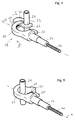
- Fig. 6:
- ein Ausführungsbeispiel für eine einen Kraftspeicher und ein Getriebe enthaltene Baueinheit, welche bei den in den Figuren 1 bis 3 dargestellten Ausführungsformen zur Anwendung kommen kann, in einer ersten Betriebsstellung;
- Fig. 7:
- die in Fig. 6 dargestellte Ausführungsform in einer zweiten Betriebsstellung;
- Fig. 8:
- die in den Figuren 6 und 7 dargestellte Ausführungsform in einer dritten Betriebsstellung; und
- Fig. 9:
- ein weiteres Ausführungsbeispiel für eine den Kraftspeicher und das Getriebe der Hubvorrichtung enthaltenden Baueinheit;
- Fig. 10:
- ein weiteres Ausführungsbeispiel für eine Hubvorrichtung; und
- Fig. 11:
- ein weiteres Ausführungsbeispiel für einen Kraftspeicher.
Claims (9)
- Vorrichtung zum Anheben und/oder Absenken einer Last auf einen bzw. von einem Lastträger mit einem Ausleger (7, 39), der schwenkbar am Lastträger (27, 29, 30) angelenkt ist, und mit am Ausleger vorgesehenen Befestigungsmitteln für eine Last, wobei der Ausleger um eine am Lastträger fixierte Achse (8) in eine angehobene Position schwenkbar ist, in welcher der Ausleger zur stabilen Positionierung der angehobenen Last am Lastträger fixierbar ist,
dadurch gekennzeichnet, daß
der Ausleger (7, 39) in einer abgesenkten Position zum Befestigen der Last am Ausleger an einem mit dem Lastträger (27, 29, 30) kraftschlüssig verbundenen Anschlag (4) anliegt und daß der Ausleger über ein Getriebe (2) mit einem Kraftspeicher (1) zur Übertragung einer Kraft des Kraftspeichers auf die Last verbunden ist. - Vorrichtung nach Anspruch 1, dadurch gekennzeichnet, daß die Last am Ausleger (7) starr befestigbar ist.
- Vorrichtung nach Anspruch 1, dadurch gekennzeichnet, daß die Last am Ausleger (7, 39) gelenkig befestigbar ist.
- Vorrichtung nach Anspruch 1, dadurch gekennzeichnet, daß der Kraftspeicher (1) und das Getriebe (2) an einem gemeinsamen Träger (3) gelagert sind und daß die Kraftrichtung, mit welcher der Kraftspeicher (1) auf das Getriebe (2) wirkt, veränderbar ist.
- Vorrichtung nach Anspruch 4, dadurch gekennzeichnet, daß die Kraftrichtungen des Kraftspeichers (1) zu beiden Seiten einer Totpunktlage des Getriebes (2) liegen, wobei auf der einen Seite der Totpunktlage die Speicherkraft durch den Anschlag (4) am gemeinsamen Träger (3) aufgenommen wird und auf der anderen Seite der Totpunktlage die Speicherkraft das Getriebe (2) in einer Hubrichtung antreibt.
- Vorrichtung nach Anspruch 5, dadurch gekennzeichnet, daß durch den Anschlag (4) ferner eine Ruheposition definiert ist, in welcher das Getriebe (2) ohne Last am Lastträger (27, 29, 30) gehalten ist.
- Vorrichtung nach Anspruch 1, dadurch gekennzeichnet, daß die Antriebskraft des Kraftspeichers (1) über einen Kraftangriffspunkt (17) auf eine am gemeinsamen Träger (3) schwenkbar gelagerte Schwinge (6) übertragbar ist und daß ein die Last aufnehmender Schwenkarm (7) mit der Schwinge (6) koppelbar ist.
- Vorrichtung nach Anspruch 7, dadurch gekennzeichnet, daß der Kraftangriffspunkt (17) des Kraftspeichers (1) durch Schwenken der Schwinge (6) in die Stellungen beidseits der Totpunktlage bringbar ist.
- Vorrichtung nach einem der Ansprüche 1 bis 8, dadurch gekennzeichnet, daß am Ausleger (7, 39) ein Zweiradhalter (18) befestigbar ist.
Priority Applications (1)
| Application Number | Priority Date | Filing Date | Title |
|---|---|---|---|
| US08/275,873 US5509776A (en) | 1993-07-22 | 1994-07-15 | Apparatus for raising and lowering a load on or from a support |
Applications Claiming Priority (2)
| Application Number | Priority Date | Filing Date | Title |
|---|---|---|---|
| DE4324669 | 1993-07-22 | ||
| DE4324669A DE4324669C1 (de) | 1993-07-22 | 1993-07-22 | Vorrichtung zum Anheben und/oder Absenken einer Last auf einen bzw. von einem Lastträger |
Publications (2)
| Publication Number | Publication Date |
|---|---|
| EP0635396A1 EP0635396A1 (de) | 1995-01-25 |
| EP0635396B1 true EP0635396B1 (de) | 1998-04-01 |
Family
ID=6493479
Family Applications (1)
| Application Number | Title | Priority Date | Filing Date |
|---|---|---|---|
| EP94110663A Expired - Lifetime EP0635396B1 (de) | 1993-07-22 | 1994-07-08 | Vorrichtung zum Anheben und/oder Absenken einer Last auf einen bzw. von einem Lastträger |
Country Status (3)
| Country | Link |
|---|---|
| EP (1) | EP0635396B1 (de) |
| AT (1) | ATE164554T1 (de) |
| DE (2) | DE4324669C1 (de) |
Families Citing this family (1)
| Publication number | Priority date | Publication date | Assignee | Title |
|---|---|---|---|---|
| DE102004035612A1 (de) * | 2004-07-22 | 2006-02-16 | Claus Ernst | Vorrichtung zum Tragen von Lasten am Äußeren eines Fahrzeuges |
Family Cites Families (3)
| Publication number | Priority date | Publication date | Assignee | Title |
|---|---|---|---|---|
| DE3513085A1 (de) * | 1985-04-12 | 1986-10-30 | Rainer 4050 Mönchengladbach Abel | Bike lifter |
| DE8805981U1 (de) * | 1988-05-05 | 1988-06-23 | Gurrath, Gerhard, Dipl.-Ing., 7000 Stuttgart | Dachlastträger mit Beladevorrichtung |
| DE4122823C2 (de) * | 1991-07-10 | 1995-05-24 | Hs Tech & Design | Hubvorrichtung zum Anheben und Absenken eines Fahrrades an einem Dachträger eines Kraftfahrzeugs |
-
1993
- 1993-07-22 DE DE4324669A patent/DE4324669C1/de not_active Expired - Fee Related
-
1994
- 1994-07-08 AT AT94110663T patent/ATE164554T1/de not_active IP Right Cessation
- 1994-07-08 DE DE59405562T patent/DE59405562D1/de not_active Expired - Fee Related
- 1994-07-08 EP EP94110663A patent/EP0635396B1/de not_active Expired - Lifetime
Also Published As
| Publication number | Publication date |
|---|---|
| EP0635396A1 (de) | 1995-01-25 |
| DE4324669C1 (de) | 1994-12-15 |
| ATE164554T1 (de) | 1998-04-15 |
| DE59405562D1 (de) | 1998-05-07 |
Similar Documents
| Publication | Publication Date | Title |
|---|---|---|
| EP2176117B1 (de) | Faltrad | |
| EP0593803B1 (de) | Vorrichtung zum Positionieren von Lasten | |
| DE3005594C2 (de) | Vorrichtung zum lösbaren Anschließen eines Ladegerätes an die Tragvorrichtung eines Fahrzeuges | |
| EP0918684B1 (de) | Klappfahrrad | |
| DE3923695C1 (de) | ||
| DE19960012C1 (de) | Vorrichtung zur Verriegelung zweier relativ zueineander verstellbarer, zwangsgeführter Elemente | |
| EP0933242A1 (de) | Antriebseinrichtung für einen Verdeckkastendeckel | |
| DD219985A5 (de) | Ausschwingtuer mit betaetigungseinrichtung | |
| EP0716004A1 (de) | Schwenkschiebetür für Fahrzeuge zur Personenbeförderung | |
| DE3927086A1 (de) | Zubehoer fuer fahrzeuge und befestigungsvorrichtung dafuer, sowie herstellverfahren fuer einen adapter mit versteifung fuer das zubehoer | |
| EP3771627B1 (de) | Elektrofahrrad- akkuhalterungsensemble | |
| DE3335173A1 (de) | Dachstaender fuer kraftfahrzeuge, insbesondere pkw | |
| EP3658445A1 (de) | Schaltbare seitenabstützvorrichtung für zweiräder sowie deren verwendung und verfahren zur kopplung der seitenabstützvorrichtung an ein antriebszugmittel des zweirads | |
| DE3211367A1 (de) | Zweirad, insbesondere fahrrad mit einem staender | |
| DE4324669C1 (de) | Vorrichtung zum Anheben und/oder Absenken einer Last auf einen bzw. von einem Lastträger | |
| EP0562429A1 (de) | Erdbohreinrichtung | |
| DE102021125388B4 (de) | Klappbares Fahrrad | |
| EP0388363B1 (de) | Anhängevorrichtung für Fahrzeuge | |
| DE1143724B (de) | Vorrichtung zur formschluessigen Verriegelung einer seitlich verschwenkbaren Kraftwagen-lenksaeule in der Betriebsstellung | |
| AT396743B (de) | Krankenfahrstuhl | |
| DE102004008451A1 (de) | Fahrzeuggegenstandsträger | |
| DE3503806A1 (de) | Dachluke, insbesondere fuer fahrzeuge | |
| DE4428714A1 (de) | Kupplungsvorrichtung für Zugmittel an einem Rollstuhl | |
| AT524113B1 (de) | Fahrrad-Trägervorrichtung | |
| DE2630375C2 (de) | Türanordnung, insbesondere für Behälter, Behälterwagen o.dgl. |
Legal Events
| Date | Code | Title | Description |
|---|---|---|---|
| PUAI | Public reference made under article 153(3) epc to a published international application that has entered the european phase |
Free format text: ORIGINAL CODE: 0009012 |
|
| AK | Designated contracting states |
Kind code of ref document: A1 Designated state(s): AT DE ES FR GB IT NL SE |
|
| 17P | Request for examination filed |
Effective date: 19950210 |
|
| ITCL | It: translation for ep claims filed |
Representative=s name: JACOBACCI CASETTA & PERANI S.P.A. |
|
| RAP1 | Party data changed (applicant data changed or rights of an application transferred) |
Owner name: HS PRODUCTS AG SYSTEMTECHNIK UND PRODUKTMANAGEMENT |
|
| 17Q | First examination report despatched |
Effective date: 19960917 |
|
| GRAG | Despatch of communication of intention to grant |
Free format text: ORIGINAL CODE: EPIDOS AGRA |
|
| GRAG | Despatch of communication of intention to grant |
Free format text: ORIGINAL CODE: EPIDOS AGRA |
|
| GRAH | Despatch of communication of intention to grant a patent |
Free format text: ORIGINAL CODE: EPIDOS IGRA |
|
| GRAH | Despatch of communication of intention to grant a patent |
Free format text: ORIGINAL CODE: EPIDOS IGRA |
|
| GRAA | (expected) grant |
Free format text: ORIGINAL CODE: 0009210 |
|
| AK | Designated contracting states |
Kind code of ref document: B1 Designated state(s): AT DE ES FR GB IT NL SE |
|
| PG25 | Lapsed in a contracting state [announced via postgrant information from national office to epo] |
Ref country code: NL Free format text: LAPSE BECAUSE OF FAILURE TO SUBMIT A TRANSLATION OF THE DESCRIPTION OR TO PAY THE FEE WITHIN THE PRESCRIBED TIME-LIMIT Effective date: 19980401 Ref country code: ES Free format text: THE PATENT HAS BEEN ANNULLED BY A DECISION OF A NATIONAL AUTHORITY Effective date: 19980401 |
|
| REF | Corresponds to: |
Ref document number: 164554 Country of ref document: AT Date of ref document: 19980415 Kind code of ref document: T |
|
| ET | Fr: translation filed | ||
| REF | Corresponds to: |
Ref document number: 59405562 Country of ref document: DE Date of ref document: 19980507 |
|
| ITF | It: translation for a ep patent filed | ||
| GBT | Gb: translation of ep patent filed (gb section 77(6)(a)/1977) |
Effective date: 19980601 |
|
| PG25 | Lapsed in a contracting state [announced via postgrant information from national office to epo] |
Ref country code: SE Free format text: LAPSE BECAUSE OF FAILURE TO SUBMIT A TRANSLATION OF THE DESCRIPTION OR TO PAY THE FEE WITHIN THE PRESCRIBED TIME-LIMIT Effective date: 19980701 |
|
| NLV1 | Nl: lapsed or annulled due to failure to fulfill the requirements of art. 29p and 29m of the patents act | ||
| PLBE | No opposition filed within time limit |
Free format text: ORIGINAL CODE: 0009261 |
|
| STAA | Information on the status of an ep patent application or granted ep patent |
Free format text: STATUS: NO OPPOSITION FILED WITHIN TIME LIMIT |
|
| 26N | No opposition filed | ||
| REG | Reference to a national code |
Ref country code: GB Ref legal event code: 732E |
|
| REG | Reference to a national code |
Ref country code: FR Ref legal event code: TP |
|
| REG | Reference to a national code |
Ref country code: GB Ref legal event code: IF02 |
|
| PGFP | Annual fee paid to national office [announced via postgrant information from national office to epo] |
Ref country code: AT Payment date: 20070723 Year of fee payment: 14 |
|
| PGFP | Annual fee paid to national office [announced via postgrant information from national office to epo] |
Ref country code: GB Payment date: 20070730 Year of fee payment: 14 |
|
| PGFP | Annual fee paid to national office [announced via postgrant information from national office to epo] |
Ref country code: IT Payment date: 20070726 Year of fee payment: 14 |
|
| PGFP | Annual fee paid to national office [announced via postgrant information from national office to epo] |
Ref country code: FR Payment date: 20070718 Year of fee payment: 14 |
|
| GBPC | Gb: european patent ceased through non-payment of renewal fee |
Effective date: 20080708 |
|
| PG25 | Lapsed in a contracting state [announced via postgrant information from national office to epo] |
Ref country code: AT Free format text: LAPSE BECAUSE OF NON-PAYMENT OF DUE FEES Effective date: 20080708 |
|
| REG | Reference to a national code |
Ref country code: FR Ref legal event code: ST Effective date: 20090331 |
|
| PG25 | Lapsed in a contracting state [announced via postgrant information from national office to epo] |
Ref country code: GB Free format text: LAPSE BECAUSE OF NON-PAYMENT OF DUE FEES Effective date: 20080708 |
|
| PG25 | Lapsed in a contracting state [announced via postgrant information from national office to epo] |
Ref country code: IT Free format text: LAPSE BECAUSE OF NON-PAYMENT OF DUE FEES Effective date: 20080708 Ref country code: FR Free format text: LAPSE BECAUSE OF NON-PAYMENT OF DUE FEES Effective date: 20080731 |
|
| PGFP | Annual fee paid to national office [announced via postgrant information from national office to epo] |
Ref country code: DE Payment date: 20090923 Year of fee payment: 16 |
|
| PG25 | Lapsed in a contracting state [announced via postgrant information from national office to epo] |
Ref country code: DE Free format text: LAPSE BECAUSE OF NON-PAYMENT OF DUE FEES Effective date: 20110201 |
|
| REG | Reference to a national code |
Ref country code: DE Ref legal event code: R119 Ref document number: 59405562 Country of ref document: DE Effective date: 20110201 |