EP0635196B1 - Schleuderstreuer - Google Patents
Schleuderstreuer Download PDFInfo
- Publication number
- EP0635196B1 EP0635196B1 EP94107812A EP94107812A EP0635196B1 EP 0635196 B1 EP0635196 B1 EP 0635196B1 EP 94107812 A EP94107812 A EP 94107812A EP 94107812 A EP94107812 A EP 94107812A EP 0635196 B1 EP0635196 B1 EP 0635196B1
- Authority
- EP
- European Patent Office
- Prior art keywords
- disk
- blade part
- spreader according
- centrifugal spreader
- locking
- Prior art date
- Legal status (The legal status is an assumption and is not a legal conclusion. Google has not performed a legal analysis and makes no representation as to the accuracy of the status listed.)
- Expired - Lifetime
Links
- 230000007480 spreading Effects 0.000 claims abstract description 30
- 239000000463 material Substances 0.000 claims abstract description 9
- 230000007704 transition Effects 0.000 claims description 6
- 238000006073 displacement reaction Methods 0.000 claims description 4
- 230000000284 resting effect Effects 0.000 claims description 4
- 238000010276 construction Methods 0.000 claims description 2
- 238000000605 extraction Methods 0.000 claims 1
- 210000002414 leg Anatomy 0.000 description 28
- 239000003337 fertilizer Substances 0.000 description 20
- 210000000689 upper leg Anatomy 0.000 description 9
- 239000002245 particle Substances 0.000 description 8
- 230000008859 change Effects 0.000 description 5
- 230000001133 acceleration Effects 0.000 description 2
- 230000009471 action Effects 0.000 description 1
- 230000005540 biological transmission Effects 0.000 description 1
- 230000015572 biosynthetic process Effects 0.000 description 1
- 230000000694 effects Effects 0.000 description 1
- 238000005516 engineering process Methods 0.000 description 1
- 230000004720 fertilization Effects 0.000 description 1
- 230000010355 oscillation Effects 0.000 description 1
- 230000000149 penetrating effect Effects 0.000 description 1
- 230000000630 rising effect Effects 0.000 description 1
- 239000007921 spray Substances 0.000 description 1
- 239000006228 supernatant Substances 0.000 description 1
Images


Classifications
-
- A—HUMAN NECESSITIES
- A01—AGRICULTURE; FORESTRY; ANIMAL HUSBANDRY; HUNTING; TRAPPING; FISHING
- A01C—PLANTING; SOWING; FERTILISING
- A01C17/00—Fertilisers or seeders with centrifugal wheels
- A01C17/006—Regulating or dosing devices
- A01C17/008—Devices controlling the quantity or the distribution pattern
-
- A—HUMAN NECESSITIES
- A01—AGRICULTURE; FORESTRY; ANIMAL HUSBANDRY; HUNTING; TRAPPING; FISHING
- A01C—PLANTING; SOWING; FERTILISING
- A01C17/00—Fertilisers or seeders with centrifugal wheels
- A01C17/001—Centrifugal throwing devices with a vertical axis
Definitions
- the invention relates to a centrifugal spreader for free-flowing Grit with the characteristics of the generic term of independent claims 1 to 3.
- Centrifugal spreaders of the aforementioned construction serve in particular in agriculture to distribute fertilizer.
- the centrifugal spreader has to meet different operating conditions can be adapted, e.g. for normal fertilization, Late fertilizers, border spreading.
- the spread of the individual centrifugal discs for setting different ones Working widths can be variable.
- centrifugal spreaders DE 17 57 834 U, EP 281 886 A1, EP 292 650 B1
- the centrifugal disc is adjustable in several ways.
- they consist of two wing parts, from which the inner at its inner end on the disc is pivotally mounted, while the outer wing part the inner is guided.
- the angle of attack of the spreader vane in the disc plane be varied. So that the wing can be in a featured or deferred position and thus the point of departure of the grit particles on the orbit to adjust.
- the outer Wing part By sliding the outer Wing part on the inside can be the length of the throwing wing vary and thus its outer edge, which at the same time forms the departure edge for the grit particles, at different distances from the center of the disc or adjust the outlet opening and thereby in particular the working width vary.
- the pivoting inner wing part is in the area its outer end with a bolt in a part-circular Slit the disc out.
- the inside and the outer wing part are designed as a U-profile, wherein the outer wing part overlaps the inner wing part.
- the U-profile opens in the direction of rotation of the centrifugal disc.
- the outer wing part in its upper U-leg on a longitudinal slot, by means of which the wing part on one the inner wing part upwards outstanding and attached to it stud bolts is.
- the object of the invention for the spreader vanes to propose training that enables both settings can be made with just one hand or change.
- This object is achieved in that the arcuate slot on the disc and the longitudinal slot crossing each other on the outer wing part are arranged, and that a single fixing means with one crossing both slots at their crossing point Management body is provided.
- the outer on the inner wing part is only one the only two-slot guide, e.g. a bolt, necessary and can fix the Throwing wing in any position by just one
- the only means of determination are the part of the management body is or attacks this and the spreader wing on the disc or the two parts of the spreader vanes tense together. It can be a screw connection, a preloaded bayonet lock, one act cam-controlled clamp connection or the like.
- the invention is therefore based on the further object when changing both settings with only one Handle the risk of changing the setting during to avoid operation.
- the disc has several on the same radius with respect to the pivot bearing and that outer wing part several in the direction of displacement horizontal snap-in receptacles each have a snap-in receptacle on the outer wing part and on the disc Cover can be brought, and that a single one in itself engaging locking means provided is.
- both the snap-in receptacles are present the disc and on the swivel lever, as well as the bolt on the outer wing part and the locking means on the swivel lever in planes perpendicular to each other, nevertheless can only by pressing the swivel lever Adjustment of the spreader wing or wing parts as desired changed and a positive in every setting Definition can be achieved.
- the snap-in receptacles on the pane and on the outer wing part can be equally spaced among themselves, but also be arranged with varying distances. This sets up according to the need for setting options.
- Swivel lever can be arranged as an actuator. Instead, it can also be used on a vertical actuation axis be arranged. In both cases the Latches preferably under one of them in the locked position urgent spring force.
- the bolt is as rotatable bolt formed, the diameter of which is little is smaller than the one of the rest shots and the on opposite sides to one of the width of the slot corresponding width is flattened. In this way can be done in two rotated 90 ° positions outer wing part on the inner and this on the disc adjust while in an intermediate position the bolt with its circular sections in the circular extensions engages and the inner wing part on the disc or blocked the outer on the inner wing part.
- Another embodiment is characterized in that a radius with respect to the Schwlenklager rest recordings are formed in the disc as slots, the radial on the pivot bearing of the inner Wing part lie, and the locking shots on the outside Wing part in a disk-parallel leg with Uniform slots spaced one behind the other are.
- the locking shots are through short slits formed side by side on the disc are arranged and run on radials.
- These slits can be slotted with the same shape outer wing part, one behind the other in the direction of the wing are arranged to cover so that the Throwing wing in turn by a single locking means in the set position can be locked.
- the Latching means have a nose, which in the slots of outer wing part and disc engages almost free play.
- the angular adjustment of the inner wing part and the length adjustment by means of outer wing part different locking shots and a latch or a nose for each adjustment option available, however, on a single actuator are arranged so that after setting the throwing wing in the desired position by a single handle can be fixed.
- the fixing means, the locking means or the actuator of the various embodiments are on the back of the wing and / or at the bottom of the Washer provided so that it is easily from the side or are accessible below and have no negative impact the transfer of the spreading material from the discharge opening into the Spreading wing or the transport of the spreading material in the spreading wing can exercise.
- the setting options on the one hand and the dynamic Loads require flawless Guide the two wing parts together. It is therefore provided that the outer wing part at the back of the inner wing part is arranged and by means of a Slot on one at the back of the inner wing part protruding bolt is guided.
- the measure serves the same purpose of stable leadership, after which the inner wing part is a Z-profile, of the lower leg resting on the disc into one U-profile is formed, and that the outer wing part with its disc-parallel leg in this U-profile is led. Then is also the leg parallel to the disk the outer wing part also to a U-profile trained, this is properly on the inner wing part led, whereby by the U-profile shape of the disk parallel Thighs also stabilize and Stiffening of the two wing parts is achieved. Further can in this way the entire guide and Adjustment means arranged on the back of the wing be so that neither the wing protrudes upwards constructive parts, still in the direction of rotation in front of the wing There are parts on the disc. It will thus also the movement of the fertilizer particles in the wing or in no way obstructed or negative on the disc influenced.
- the outer wing part is preferably a Z-profile trained and overlaps with its upper in the direction of rotation of the pub pointing the corresponding one Leg of the inner wing part.
- both wing parts run advantageously increasing in the direction of rotation, the leg of the outer wing part is narrower so that its leading Edge below the leading edge of the inner Wing part remains. This ensures that the Passing the spreader vane through the outlet opening only a single narrow edge "cuts through” the fertilizer flow and, above all, thereby Impact losses can be avoided.
- the inner and outer wing part can at the transition from the vertical to the disc-parallel lower Leg in the direction of rotation forward to a kind of bar be formed to when the outer wing member Periphery of the disc towers over the vertical Thighs of fertilizer particles not on the edge of the disc can tip down, but until the end of the Wing are performed.
- the centrifugal disc is usually on its drive shaft with a locking hub on top of it attached. To avoid that between Push the locking hub and spreading wing through the fertilizer particles and therefore not properly accelerated to the outside the spreader wing lies with its inner end of the Locking hub on. To this plant in every setting too ensure, it is provided that the inner wing part guided on its pivot bearing by means of an elongated hole and that the arcuate slot in the disc or the rest recordings on one radius with another Center point are such that the inner wing part in every angular position of the spreader vane against the locking hub is pushed.
- the disc parallel Leg of the inner wing part at its outer end one of the locking receptacles on the outer wing part or on the Disc has corresponding recesses, which of the Advice is reached, so that the inner wing part at its outer end by means of the catch is fixed.
- the disc in addition to the arc-shaped slot or the locking receptacles parallel to this further inside guide slot for the inner wing part and this on its disc parallel Leg a extending in the wing direction Elongated hole and that the guide slot, the elongated hole and the linear slot in the outer Through the wing part is provided, which is also the maximum extension length of the outer wing part limited.
- the guide pin which is attached to one by means of a head End and a nut on a thread at the other end also defines the wing in the vertical direction at the same time as a stop for the maximum extension length of the outer wing part.
- the guide slot in the swivel range strongly imagined throwing wing one inwards to Disc section guided section.
- Training serves as a security measure for the following case: at Two-headers spread between the two discs the shaft for the agitator arranged in the container. It consequently the spreading wing must not reach a length where he hits the agitator shaft. On the other hand is at maximum extension length of the outer wing part the protruding length from the angular position depending on the wing on the disc.
- the centrifugal discs are plate-shaped, so form one flat conical surface. Because the disc-parallel legs the wings are flat, they do not lie on the conical surface fed up. The situation is getting worse, ever stronger the position of the wing from a radial of the Disc deviates. Due to the two-part training of Wing inevitably leads to tension. This Disadvantages are eliminated according to the invention in that the Centrifugal disc at least in the area of the throwing wing and whose adjustment range is a molded, flat support surface for the throwing wing, which essentially has one has trapezoidal outline.
- the spreader vane therefore offers one in every position flat support surface, so that on the one hand the adjustment is easily possible, on the other hand not spreading material under the spreader wing can reach. Also tension, overuse and damage to the for adjustment necessary functional parts are avoided.
- the forward leg of the inner wing part a sawtooth profile on its leading edge has, with advantageously each tooth of the sawtooth profile one approximately perpendicular to the longitudinal extension of the throwing wing running flank and one from the inside out has flank in the direction of rotation of the disc.
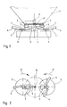
- the centrifugal spreader according to Figure 1 for example is picked up by the three-point linkage of a tractor, has a container 1 receiving the grit. Of the Container has two outlet openings 2, each with one subsequent outlet shaft 3, below which with short distance the spreader vanes 4 each have a centrifugal disc 5 circulate.
- the centrifugal discs 5 sit on Drive shafts 6, on which they by means of locking hubs 7 are attached.
- the drive shafts 6 are from the PTO of the tractor driven by a gear, whose housing is indicated schematically in Fig. 1.
- the transmission has a further shaft 8 for a in the container 1 revolving agitator 9.
- the two centrifugal disks 5 are mounted so that the spreader vanes 4 to each other by 90 ° are offset, as shown in Figure 2. Furthermore turn the centrifugal discs 5 counterclockwise, like is indicated by the directional arrows 10 in Figure 2.
- the spreader vanes 4 consist of all embodiments an inner wing part 11 and an outer wing part 12 ( Figure 3), the inner wing member 11 on the Washer is fixed while the outer wing member 12th is movable to change the wing length.
- the inner wing part 11 closes with its inner Edge 13 on the locking hub 7, while the outer Edge of the spreader vane 4, namely the outer edge 14 of the outer wing part 12, the departure edge for the fertilizer forms.
- the inner wing part 11 is close to its inner edge 13 pivotally mounted on an axis 15 so that the angle of attack of the spreader vane 4 adjustable in the disc plane is.
- the centrifugal disc 5 at a radial distance from the pivot axis 15 arcuate, namely part-circular slot 16 ( Figure 4) in which a guide member 17 ( Figure 3) is guided on the inner wing part 11, which in the 3 to 8 designed as a bolt is.
- the Centrifugal disc 5 locking receptacles 18 provided in the a locking means 19 in the form of a nose on an actuator 20 engages positively.
- the exemplary embodiments according to FIGS. 3 to 6 are the snap-in receptacles 18 as slots 21 arranged side by side formed on radii with the pivot axis 15 as Center.
- the actuator 20 is as Swivel lever formed on a horizontal axis 22, which is attached to the inner wing part 11, mounted and is shown in phantom in FIG unlocked position in the with solid lines shown latch position is pivotable in the nose 19 engages in one of the slots 21.
- the outer wing part 12 is on the inner wing part 11 guided linearly displaceable, as in Figure 5 in more detail can be seen.
- the inner wing part 11 is a Z-profile formed, so has an approximately vertical web 23, an angled in the direction of rotation of the disc upper leg 24 and one bent backwards lower leg 25 on by another bent leg 26 to an open top U-profile is formed.
- the vertical leg 23 and the top of the centrifugal disc 5 and the top Leg 24 are used to guide the fertilizer at his Acceleration to the outside.
- the outer wing part 12 is also designed as a Z-profile, consists of a vertical web 27, one pointing in the direction of rotation upper leg 28 and a lower leg 29 again formed into an upwardly open U-profile is.
- the outer wing part 12 has in its vertical Leg 27 a disk-parallel slot 30, by means of which the outer wing part 12 on one the inner wing part 11 on the vertical leg 23 welded bolt 31 is guided. Furthermore, the outer wing part on his lower leg 29 a further slit 32 running parallel to the disk the on the sliding in the slot 16 guide member 17th is led. The outer wing member 12 also instructs his lower leg 29, directly on Transition to the vertical leg 27, several in the pull-out direction the wing part arranged one behind the other Rastaufnahman 33, which in turn as slots 34 are trained.
- the slots 34 can be depending on Angle of attack the spreader vane 4 with the corresponding Slit 21 in the disc 5 aligned so that the nose 19 on the actuator 20 simultaneously in one of the Slots 34 and 21 engages and thus the Spreader vane 4 in terms of its angular position and fixed in terms of its length.
- the Locking receptacles 33 on the outer wing part each as a hole-shaped Extensions 38 and 39 on the guide slot 16 in the centrifugal disc 5 or on the guide slot 32 in the lower leg 29 of the outer throwing wing 12 educated.
- the hole-shaped extensions 38, 39 of the Slots 16 and 32 can be divided into several Index positions aligned so that both the angle of attack of the throwing wing 4, as well as its length with one only locking means can be adjusted.
- this Exemplary embodiment has the locking means 19 in the form a bolt on one of the wing lying on the top Stop head and a hole-shaped extensions Has 38 or 39 penetrating pin 40, the under the action of a pulling him into the rest position Spring 41 stands. By reaching under the centrifugal disc 5 and pressure on the pin 40 or the spring 41 can Bolt raised and the spreader 4 or only the outer Wing part 12 can be adjusted. Instead, the Bolts can also be lifted by pulling the stop head.
- Locking means in the form of a bolt on the opposite Sides are flattened to a width that the width of the two slots 16, 32 at the narrowest Place corresponds, so that in two offset by 90 ° Rotational positions of the spreader vanes 4 pivoted or the outer Wing part 12 can be moved while in one order 45 ° offset the opposing pitch circle surfaces the bolt both in extension 38 of the Slot 16, as well as in the extension 39 of the slot 32 engage and the spreader vane in the set Lock position.
- the exemplary embodiment according to FIGS. 13 and 14 distinguishes different from the exemplary embodiments described above essentially only by the following features:
- the centrifugal disc 5 another part-circular Guide slot 43 with the same center, in which engages a guide pin 44.
- An actuator 20 serves upwards bent flat ribbon, which on a pin 45 under Effect of a coil spring 46 in the locking position is pushed down.
- the actuator 20 has the locking means 19 in shape of a bolt.
- FIGS. 15 and 16 differs different from the previously described embodiment only by the execution of the actuator that in its disk-parallel section as a corrugated tape 47 own resilience is trained.
- Both the ribbon of the actuator 20 according to Figures 13 and 14, such also the corrugated band 47 of the actuating member according to FIG. 15 and 16, are in the locking position in the rear U-profile represents the two wing parts 11 and 12.
- Figure 17 shows the bolt-shaped locking means 19 of the embodiment 15 and 16 and the guide pin 44 in an enlarged view Presentation.
- an axis 48 is pivotally mounted, locking shots in Formed by angled slots 49 while a latch 50 is attached to the outer wing part 12 is so that the outer wing member 12 in different Extension lengths can be locked.
- the Actuator 20 as a locking means on a nose 51 in radial slots of the disc 6, as in the embodiment 3 to 8 are provided, engages.
- the inner edge 13 of the inner wing part 11 of the locking hub 7 is present to prevent fertilizer from passing through there and not properly through the spreader 4 is accelerated to the outside.
- the swivel axis engages 15 of the spreader vane 4 in an elongated hole 15 'of the inner Wing part 11 a.
- the guide slot is 16 in the disc 5 is not arranged on a disc radius, but has an eccentric turning center, so that also when resetting the inner wing part 11 in Connection with the elongated hole 15 'is always ensured that the inner edge 13 of the wing part 11 of the locking hub 7 is present.
- the fertilizer gets through the centrifugal acceleration each on the inner side of the vertical leg 23, 27 of the two wing parts pushed.
- Locking means 19 in the form of a bolt in turn from below the locking recordings of the disc 5 and the outer wing part 12 a.
- the bolt sits on one of the actuators forming, bow-type spring 41, at whose the Periphery of the disc 5 near the end of a sleeve 58 for Insert a rod or pin-shaped tool is attached so that on the one hand the user is not under the disc 5 must grip, on the other hand the spring force the spring 41 can be easily overcome when unlocking can.
- the snap-in receptacles are formed as holes 38 and not through one Slot connected.
- the inner wing part 11 a sawtooth profile on its leading edge in the direction of rotation 59 from several teeth 60.
- Each tooth 60 has a flank 61 which is approximately perpendicular to the longitudinal extent of the spreader vane 4 in the direction of rotation runs while the other flank 62 outwards in Direction of rotation is set.
- the leading edge occurs thus not suddenly over a long length in the Exit opening or leaving the outlet shaft Fertilizer spray.
- the flanks 62 prevent the particles reflect outwards from the fertilizer jet but make sure that the particles are inside be held and get into the spreader wing to first to be accelerated outwards by this.
- the inner wing part 11 has an elongated hole 65 on.
- the length A of the elongated hole 65 corresponds to the radial one Offset A of the sections 63, 64 of the slot 43 in the Disc 5 (Fig. 24).
- the guide pin 44 (see Fig. 22, 23) of the linear slot 32 in the outer wing part 12, the elongated hole 65 in the inner wing part 11 and Guide slot 43 penetrated in the disc acts as Stop at the moment when the wing 4 an angular position at the transition of sections 63 and 64 of the guide slot reached. The supernatant in this position is still not critical. With further pivoting, which in the rest is only possible when the locking means 19 is unlocked, the outer wing part by the guide pin 44th automatically pulled inwards.
- the centrifugal disc 5 is plate-shaped, such as 1 and 3 in particular. So she points the shape of a flat truncated cone, which with its smaller flat base surface sits on the shaft 6.
- the disk-parallel legs 25, 29 of the inner and outer Wing parts 11, 12 have a finite width, so that they do not lie snugly against the conical surface of the disk 5 can. This becomes particularly serious when the wing 4 is pivoted into a reset position.
- By the two-piece structure of the wing creates constraining forces in the guides and the catches. To avoid this is the centrifugal disc in the swivel range of the Spreader vane to a flat support surface 66 (FIG. 24) formed, which has an approximately trapezoidal outline.
Landscapes
- Life Sciences & Earth Sciences (AREA)
- Soil Sciences (AREA)
- Environmental Sciences (AREA)
- Fertilizing (AREA)
- Centrifugal Separators (AREA)
- Coating Apparatus (AREA)
Description
- Figur 1 :
- eine schematische Ansicht eines Zweischeibenstreuers;
- Figur 2 :
- eine schematische Draufsicht auf den Schleuderstreuer gemäß Figur 1 ohne den Vorratsbehälter;
- Figur 3 :
- eine Seitenansicht einer Schleuderscheibe mit einer ersten Ausführungsform der Wurfflügel;
- Figur 4 :
- eine Draufsicht auf die Ausführungsform gemäß Figur 3;
- Figur 5 :
- einen Schnitt V-V gemäß Figur 3;
- Figur 6 :
- eine vergrößerte Draufsicht auf einen der beiden Wurfflügel der Schleuderscheibe gemäß Figur 3 und 4;
- Figur 7 :
- eine Detailansicht des äußeren Flügelteils des Wurfflügels gemäß Figur 6;
- Figur 8 :
- eine Teilansicht der Schleuderscheibe in der Ausführung gemäß Figur 3 bis 6;
- Figur 9, 10:
- Seitenansicht und Draufsicht eines weiteren Ausführungsbeispiels des Wurfflügels;
- Figur 11,12:
- eine dritte Ausführungsform in Seitenansicht und Draufsicht;
- Figur 13,14:
- eine vierte Ausführungsform in Seitenansicht und Draufsicht;
- Figur 15,16:
- eine fünfte Ausführungsform in Seitenansicht und Draufsicht;
- Figur 17 :
- eine vergrößerte Detailansicht der Ausführungsform gemäß 15 und 16;
- Figur 18 :
- eine Seitenansicht einer weiteren Ausführungsform des Wurfflügels;
- Figur 19 :
- eine schematische Draufsicht auf die Schleuderscheibe mit dem inneren Flügelteil;
- Figur 20 :
- einen Wurfflügel im Schnitt;
- Figur 21 :
- eine Seitenansicht eines weiteren Ausführungsbeispiels und
- Figur 22 :
- eine Ausführungsform mit einem Sägezahnprofil am Wurfflügel
- Figur 23 :
- eine der Fig. 22 entsprechende, jedoch abgewandelten Ausführungsform und
- Figur 24 :
- eine Sprengzeichnung der Ausführungsform nach Fig. 23
Claims (38)
- Schleuderstreuer für rieselfähiges Streugut, bestehend aus einem Vorratsbehälter (1) mit wenigstens einer Auslauföffnung (2) einstellbaren Querschnitts und wenigstens einer Schleuderscheibe (5), die unter der Auslauföffnung umläuft und wenigstens einen zweiteiligen Wurfflügel (4) aufweist, dessen inneres Flügelteil (11) zur Einstellung des Anstellwinkels des Wurfflügels in der Scheibenebene nahe dem Zentrum der Scheibe schwenkbar gelagert und mit Abstand davon in einem bogenförmigen Schlitz (16) der Scheibe geführt ist und dessen äußeres Flügelteil (12) mittels eines Längsschlitzes (32) gegenüber dem inneren zur Einstellung der Flügellänge verschiebbar ist, wobei beide Flügelteile in der eingestellten Position festlegbar sind, dadurch gekennzeichnet, daß der bogenförmige Schlitz (16) an der Scheibe (5) und der Längsschlitz (32) an dem äußeren Flügelteil (12) einander kreuzend angeordnet sind, und daß ein einziges Festlegungsmittel mit einem beide Schlitze an deren Kreuzungspunkt durchgreifenden Führungsorgan (17) vorgesehen ist.
- Schleuderstreuer für rieselfähiges Streugut, bestehend aus einem Vorratsbehälter mit wenigstens einer Auslauföffnung einstellbaren Querschnitts und wenigstens einer Schleuderscheibe, die unter der Auslauföffnung umläuft und wenigstens einen zweiteiligen Wurfflügel aufweist, dessen inneres Flügelteil nahe dem Zentrum der Scheibe schwenkbar gelagert und mit Abstand davon zur Einstellung des Anstellwinkels des Wurfflügels in der Scheibenebene festlegbar ist und dessen äußeres Flügelteil gegenüber dem inneren zur Einstellung der Flügellänge linear verschiebbar ist, dadurch gekennzeichnet, daß die Scheibe (5) mehrere auf dem gleichen Radius bezüglich des Schwenklagers (15) und das äußere Flügelteil (12) mehrere in Verschieberichtung liegende Rastaufnahmen (18,33) aufweisen, daß je eine Rastaufnahme (18,33) am äußeren Flügelteil (12) und eine Rastaufnahme an der Scheibe (5) zur Deckung bringbar sind, und daß ein einziges in die sich deckenden Rastaufnahmen eingreifendes Rastmittel (19) vorgesehen ist.
- Schleuderstreuer für rieselfähiges Streugut, bestehend aus einem Vorratsbehälter mit wenigstens einer Auslauföffnung einstellbaren Querschnitts und wenigstens einer Schleuderscheibe, die unter der Auslauföffnung umläuft und wenigstens einen zweiteiligen Wurfflügel aufweist, dessen inneres Flügelteil nahe dem Zentrum der Scheibe schwenkbar gelagert und mit Abstand davon zur Einstellung des Anstellwinkels des Wurfflügels in der Scheibenebene festlegbar ist und dessen äußeres Flügelteil gegenüber dem inneren zur Einstellung der Flügellänge linear verschiebbar ist, dadurch gekennzeichnet, daß die Scheibe (5) mehrere auf dem gleichen Radius bezüglich des Schwenklagers (15) liegende Rastaufnahmen (18) und das äußere Flügelteil einen sich etwa scheibenparallel erstreckenden Riegel (50) aufweist, und daß ein einziges Betätigungsorgan (20) in Form eines sich flügelparallel erstreckenden, an einer etwa scheibenparallelen Achse ortsfest gelagerten Schwenkhebels mit mehreren in seiner Erstreckungsrichtung liegenden Rastaufnahmen (49) für den Riegel (50) und einem Rastmittel (51) für die Rastaufnahmen (33) an der Scheibe vorgesehen ist.
- Schleuderstreuer nach Anspruch 2, dadurch gekennzeichnet, daß die Rastaufnahmen (18,33) an der Scheibe (5) und am äußeren Flügelteil (12) unter sich jeweils abstandsgleich angeordnet sind.
- Schleuderstreuer nach Anspruch 2 oder 4, dadurch gekennzeichnet, daß die Rastaufnahmen (18, 33) an der Scheibe (5) und am äußeren Flügelteil (12) konturengleich ausgebildet sind, und daß das Rastmittel (19) einen einzigen Riegel aufweist, der in die fluchtenden Rastaufnahmen von äußerem Flügelteil und Scheibe eingreift.
- Schleuderstreuer nach der Anspruch 4 oder 5, dadurch gekennzeichnet, daß die Rastaufnahmen (18) an der Scheibe (5) als kreisförmige Löcher (38) ausgebildet sind, und daß das äußere Flügelteil (12) in einem scheibenparallelen Schenkel (29) eine Reihe entsprechend kreisförmiger Löcher (39) aufweist.
- Schleuderstreuer nach einem der Ansprüche 4 bis 6, dadurch gekennzeichnet, daß die kreisförmigen Löcher (38) an der Scheibe (5) als Erweiterungen des bogenförmigen Schlitzes (16) ausgebildet sind.
- Schleuderstreuer nach einem der Ansprüche 1, 2 und 4 bis 7, dadurch gekennzeichnet, daß die kreisförmigen Löcher (39) in dem scheibenparallelen Schenkel (29) des äußeren Flügelteils (17) durch einen Schlitz (32) gleicher Breite wie die des bogenförmigen Schlitzes (16) in der Scheibe (5) miteinander verbunden sind.
- Schleuderstreuer nach einem der Ansprüche 4 bis 8, dadurch gekennzeichnet, daß der Riegel (11) als Bolzen (40,42) ausgebildet ist, der von oben oder unten in die fluchtenden Rastaufnahmen (18,33) in der Scheibe (5) und dem äußeren Flügelteil (12) eingreift.
- Schleuderstreuer nach einem der Ansprüche 4 bis 9, dadurch gekennzeichnet, daß das Rastmittel (19) an einem ihn in die Raststellung drängenden Schwenkhebel als Betätigungsorgan angeordnet ist.
- Schleuderstreuer nach einem der Ansprüche 4 bis 9, dadurch gekennzeichnet, daß das Rastmittel (19) Teil eines im wesentlichen vertikal verschieblichen Zapfens (40) ist.
- Schleuderstreuer nach einem der Ansprüche 4 bis 11, dadurch gekennzeichnet, daß das Rastmittel (19) unter einer es in die Raststellung drängenden Federkraft (41,46,47) steht.
- Schleuderstreuer nach einem der Ansprüche 4 bis 12, dadurch gekennzeichnet, daß das Rastmittel (19) als drehbarer Bolzen (42) ausgebildet ist, dessen Durchmesser wenig kleiner als derjenige der Rastaufnahmen (38, 39) ist und der an gegenüberliegenden Seiten zu einer der Breite des Schlitzes (16,32) entsprechenden Breite abgeflacht ist.
- Schleuderstreuer nach Anspruch 2, dadurch gekennzeichnet, daß die auf einem Radius bezüglich des Schwenklagers (15) liegenden Rastaufnahmen (18) in der Scheibe (5) als Schlitze (21) ausgebildet sind, die auf Radialen bezüglich des Schwenklagers (15) des inneren Flügelteils (11) liegen, und daß die Rastaufnahmen (33) am äußeren Flügelteil (12) in einem scheibenparallelen Schenkel (29) mit Abstand hintereinander angeordnete, gleichförmige Schlitze (34) sind.
- Schleuderstreuer nach Anspruch 2 und 14, dadurch gekennzeichnet, daß das Rastmittel (19) eine Nase aufweist, die in die Schlitze (21,34) in dem äußeren Flügelteil (12) und in der Scheibe (5) annähernd spielfrei eingreift.
- Schleuderstreuer nach Anspruch 3, dadurch gekennzeichnet, daß als Rastaufnahmen (18) in der Scheibe (5) nebeneinander angeordnete Schlitze (21) dienen, die auf Radialen bezüglich des Schwenklagers (15) des inneren Flügelteils (11) liegen, und daß der Schwenkhebel (20) an seinem Ende ein in die Schlitze (21) der Scheibe (5) eingreifende Nase (51) als Rastmittel und auf seiner Länge verteilt angeordnete Schlitze (49) als Rastaufnahmen aufweist, mit denen er den Riegel (50) am äußeren Flügelteil (12) übergreift.
- Schleuderstreuer nach Anspruch 16, dadurch gekennzeichnet, daß die Schlitze (49) am Schwenkhebel (20) abgewinkelt sind.
- Schleuderstreuer nach einem der Ansprüche 1 bis 16, dadurch gekennzeichnet, daß die Festlegungsmittel, die Rastmittel (19) und das Betätigungsorgan (20) an der Rückseite des Wurfflügels (4) angeordnet ist.
- Schleuderstreuer nach einem der Ansprüche 4 bis 16, dadurch gekennzeichnet, daß das Rastmittel (19) mit seiner Handhabe an der Unterseite der Scheibe (5) angeordnet ist.
- Schleuderstreuer nach einem der Ansprüche 1 bis 19, dadurch gekennzeichnet, daß das Betätigungsorgan (20, 41) als Federhebel ausgebildet ist.
- Schleuderstreuer nach einem der Ansprüche 1 bis 20, dadurch gekennzeichnet, daß das Betätigungsorgan (20,41) nahe der Schwenkachse des inneren Flügelteils (11) an der Ober- oder Unterseite der Scheibe (5) befestigt ist.
- Schleuderstreuer nach einem der Ansprüche 1 bis 21, dadurch gekennzeichnet, daß das Betätigungsorgan (20,41) an seinem freien Ende eine Hülse (58) zum Einstecken eines stabförmigen Hilfswerkzeugs aufweist.
- Schleuderstreuer nach einem der Ansprüche 1 bis 22, dadurch gekennzeichnet, daß das äußere Flügelteil (12) an der Rückseite des inneren Flügelteils (11) angeordnet ist und mittels eines Schlitzes (30) an einem an der Rückseite des inneren Flügelteils (11) abstehenden Bolzen (31) geführt ist.
- Schleuderstreuer nach einem der Ansprüche 1 bis 23, dadurch gekennzeichnet, daß das innere Flügelteil (11) ein Z-Profil ist, dessen der Scheibe (5) aufliegender unterer Schenkel (25) zu einem U-Profil ausgebildet ist, und daß das äußere Flügelteil (12) mit seinem scheibenparallelen Schenkel (29) in diesem U-Profil geführt ist.
- Schleuderstreuer nach Anspruch 24, dadurch gekennzeichnet, daß der scheibenparallele Schenkel (29) des äußeren Flügelteils (12) gleichfalls zu einem U-Profil ausgebildet ist.
- Schleuderstreuer nach einem der Ansprüche 1 bis 25, dadurch gekennzeichnet, daß der lineare Schlitz (32) bzw. die Rastaufnahmen (33) in dem scheibenparallelen Schenkel (29) des U-Profils des äußeren Flügelteils (12) angeordnet sind.
- Schleuderstreuer nach einem der Ansprüche 1 bis 26, dadurch gekennzeichnet, daß das äußere Flügelteil (12) als Z-Profil ausgebildet ist und mit seinem oberen in Drehrichtung der Scheibe (5) weisenden Schenkel (28) den entsprechenden Schenkel (24) des inneren Flügelteils (11) teilweise übergreift.
- Schleuderstreuer nach einem der Ansprüche 1 bis 27, dadurch gekennzeichnet, daß der obere Schenkel (52, 53) beider Flügelteile (11,12) in Drehrichtung ansteigend verläuft.
- Schleuderstreuer nach einem der Ansprüche 1 bis 28, dadurch gekennzeichnet, daß das innere und das äußere Flügelteil (11,12) am Übergang zu dem scheibenparallelen Schenkel (25,29) in Drehrichtung nach vorne ausgeformt sind.
- Schleuderstreuer nach einem der Ansprüche 1 bis 29, wobei die Schleuderscheibe mit einer ihr oberseitig aufsitzenden Verschlußnabe an ihrer Antriebswelle befestigt ist und die Wurfflügel mit ihrem inneren Ende der Verschlußnabe anliegen, dadurch gekennzeichnet, daß das innere Flügelteil (11) an seinem Schwenklager (15) mittels eines Langlochs (15') geführt ist, und daß der bogenförmige Schlitz (16) bzw. die Rastaufnahme in der Scheibe (5) auf einem Radius mit einem von dem Schwenklager (15) verschiedenen Mittelpunkt liegen derart, daß das innere Flügelteil (11) in jeder Winkelposition des Wurfflügels (4) gegen die Verschlußnabe (7) gedrängt wird.
- Schleuderstreuer nach einem der Ansprüche 1 bis 30, dadurch gekennzeichnet, daß der vertikale Schenkel (27) des äußeren Flügelteils (12) an seinem äußeren Ende nach hinten zu einer Handhabe (37) abgebogen ist.
- Schleuderstreuer nach einem der Ansprüche 2 bis 31, dadurch gekennzeichnet, daß der scheibenparallele Schenkel (25) des inneren Flügelteils (11) an seinem äußeren Ende eine den Rastaufnahmen (33,18) am äußeren Flügelteil (12) bzw. an der Scheibe (6) entsprechende Ausnehmung aufweist, die von dem Rastmittel (19) durchgriffen ist.
- Schleuderstreuer nach einem der Ansprüche 1 bis 32, dadurch gekennzeichnet, daß die Scheibe (6) zusätzlich zu dem bogenförmigen Schlitz (16) bzw. den Rastaufnahmen (18) einen parallel hierzu weiter innen liegenden Führungsschlitz (43) für das innere Flügelteil (11) und dieses an seinem scheibenparallelen Schenkel (25) ein sich in Flügelrichtung erstreckendes Langloch (65) aufweist, und daß ein den Führungsschlitz (43), das Langloch (65) und den linearen Schlitz (32) im äußeren Flügelteil (12) durchgreifender Führungsbolzen (44) vorgesehen ist, der zugleich die maximale Auszugslänge des äußeren Flügeteils (12) begrenzt.
- Schleuderstreuer nach einem der Ansprüche 1 bis 33, dadurch gekennzeichnet, daß der Führungsschlitz (43) in dem Schwenkbereich mit stark vorgestelltem Wurfflügel (4) einen nach innen zum Scheibenzentrum geführten Abschnitt (63) aufweist.
- Schleuderstreuer für rieselfähiges Streugut bestehend aus einem Vorratsbehälter mit wenigstens einer Auslauföffnung einstellbaren Querschnitts und wenigstens einer unter dieser umlaufenden, tellerförmigen Schleuderscheibe, die eine ebene Basisfläche zum Befestigen auf der Antriebswelle aufweist, sich in Form eines flachen Kegels nach oben erstreckt und an ihrer Oberseite wenigstens einen Wurfflügel aufweist, der an der Schleuderscheibe winkelverstellbar angeordnet und/oder längenveränderlich ausgebildet ist nach einem der Ansprüche 1 bis 34, dadurch gekennzeichnet, daß die Schleuderscheibe (5) zumindest im Bereich des Wurfflügels (4) und dessen Verstellbereichs eine eingeformte, ebene Auflagefläche (66) für den Wurfflügel (4) aufweist.
- Schleuderstreuer nach Anspruch 35, dadurch gekennzeichnet, daß die ebene Auflagefläche (66) einen im wesentlichen trapezförmigen Umriß aufweist.
- Schleuderstreuer nach einem der Ansprüche 1 bis 36, dadurch gekennzeichnet, daß der nach vorne weisende obere Schenkel (24) des inneren Flügelteils (11) an seiner vorlaufenden Kante ein Sägezahnprofil (59) aufweist.
- Schleuderstreuer nach Anspruch 17, dadurch gekennzeichnet, daß jeder Zahn (60) des Sägezahnprofils (59) eine etwa senkrecht zur Längserstreckung des Wurfflügels (4) verlaufende Flanke (61) und eine von innen nach außen in Drehrichtung der Scheibe (5) angestellte Flanke (62) aufweist.
Applications Claiming Priority (4)
| Application Number | Priority Date | Filing Date | Title |
|---|---|---|---|
| DE19934324390 DE4324390A1 (de) | 1993-07-21 | 1993-07-21 | Schleuderstreuer |
| DE4324390 | 1993-07-21 | ||
| DE4328991 | 1993-08-28 | ||
| DE19934328991 DE4328991A1 (de) | 1993-08-28 | 1993-08-28 | Schleuderstreuer |
Publications (2)
| Publication Number | Publication Date |
|---|---|
| EP0635196A1 EP0635196A1 (de) | 1995-01-25 |
| EP0635196B1 true EP0635196B1 (de) | 1998-01-21 |
Family
ID=25927872
Family Applications (1)
| Application Number | Title | Priority Date | Filing Date |
|---|---|---|---|
| EP94107812A Expired - Lifetime EP0635196B1 (de) | 1993-07-21 | 1994-05-20 | Schleuderstreuer |
Country Status (3)
| Country | Link |
|---|---|
| EP (1) | EP0635196B1 (de) |
| AT (1) | ATE162361T1 (de) |
| DE (1) | DE59405068D1 (de) |
Cited By (3)
| Publication number | Priority date | Publication date | Assignee | Title |
|---|---|---|---|---|
| DE102006056256A1 (de) * | 2006-11-27 | 2008-05-29 | Rauch Landmaschinenfabrik Gmbh | Sämaschine |
| DE102009023257A1 (de) | 2009-05-29 | 2010-12-02 | Rauch Landmaschinenfabrik Gmbh | Schleuderstreuer für rieselfähiges Streugut |
| CN111527266A (zh) * | 2017-12-05 | 2020-08-11 | 格迈纳有限责任公司 | 一种撒布车辆的撒布装置 |
Families Citing this family (7)
| Publication number | Priority date | Publication date | Assignee | Title |
|---|---|---|---|---|
| DE10028236A1 (de) * | 2000-06-07 | 2001-12-13 | Rauch Landmaschfab Gmbh | Zentrifugalstreuer, insbesondere Düngerstreuer |
| NL1016083C2 (nl) * | 2000-09-01 | 2002-03-05 | Lely Entpr Ag | Inrichting en werkwijze voor het verspreiden van korrel- en/of poedervormig materiaal, en houder voor het bevatten van een dergelijk materiaal. |
| NL1016081C2 (nl) * | 2000-09-01 | 2002-03-05 | Lely Entpr Ag | Inrichting en werkwijze voor het verspreiden van korrel- en/of poedervormig materiaal, en houder voor het bevatten van een dergelijk materiaal. |
| NL1016082C2 (nl) * | 2000-09-01 | 2002-03-05 | Lely Entpr Ag | Inrichting en werkwijze voor het verspreiden van korrel- en/of poedervormig materiaal, en houder voor het bevatten van een dergelijk materiaal. |
| NL1016080C2 (nl) * | 2000-09-01 | 2002-03-05 | Lely Entpr Ag | Inrichting en werkwijze voor het verspreiden van korrel- en/of poedervormig materiaal, en houder voor het bevatten van een dergelijk materiaal. |
| NL1016084C2 (nl) * | 2000-09-01 | 2002-03-05 | Lely Entpr Ag | Inrichting en werkwijze voor het verspreiden van korrel- en/of poedervormig materiaal, en houder voor het bevatten van een dergelijk materiaal. |
| FR2926437B1 (fr) * | 2008-01-21 | 2012-11-23 | Sulky Burel | Procede de reglage d'une machine agricole d'epandage de particules, dispositif de reglage, machine agricole d'epandage et programme d'ordinateur correspondants |
Family Cites Families (6)
| Publication number | Priority date | Publication date | Assignee | Title |
|---|---|---|---|---|
| DE2908949C2 (de) * | 1979-03-07 | 1982-07-15 | Amazonen-Werke H. Dreyer Gmbh & Co Kg, 4507 Hasbergen | Schleuderdüngerstreuer |
| DE3707188A1 (de) * | 1987-03-06 | 1988-09-15 | Amazonen Werke Dreyer H | Schleuderduengerstreuer |
| DE3906756C2 (de) * | 1989-03-03 | 1998-05-07 | Rauch Landmaschfab Gmbh | Schleuderstreuer |
| DE4100774A1 (de) * | 1990-09-25 | 1992-07-16 | Amazonen Werke Dreyer H | Schnellverschluss fuer die befestigung von wurfschaufeln |
| DK101192A (da) * | 1992-08-12 | 1994-02-13 | Laursen As A P | Roterende spredeskive med aftagelige vinger til spredning af risledygtigt materiale |
| FR2884314B1 (fr) | 2005-04-11 | 2007-06-22 | Hutchinson Sa | Codeur pour arbre mobile, dispositif comprenant un tel codeur et procede de fabrication d'un tel codeur |
-
1994
- 1994-05-20 EP EP94107812A patent/EP0635196B1/de not_active Expired - Lifetime
- 1994-05-20 AT AT94107812T patent/ATE162361T1/de not_active IP Right Cessation
- 1994-05-20 DE DE59405068T patent/DE59405068D1/de not_active Expired - Lifetime
Cited By (6)
| Publication number | Priority date | Publication date | Assignee | Title |
|---|---|---|---|---|
| DE102006056256A1 (de) * | 2006-11-27 | 2008-05-29 | Rauch Landmaschinenfabrik Gmbh | Sämaschine |
| DE102009023257A1 (de) | 2009-05-29 | 2010-12-02 | Rauch Landmaschinenfabrik Gmbh | Schleuderstreuer für rieselfähiges Streugut |
| EP2277368A1 (de) | 2009-05-29 | 2011-01-26 | Rauch Landmaschinenfabrik Gmbh | Schleuderstreuer für rieselfähiges Streugut |
| CN111527266A (zh) * | 2017-12-05 | 2020-08-11 | 格迈纳有限责任公司 | 一种撒布车辆的撒布装置 |
| RU2750685C1 (ru) * | 2017-12-05 | 2021-07-01 | Гмайнер Гмбх | Разбрасывающее устройство для разбрасывающих транспортных средств |
| CN111527266B (zh) * | 2017-12-05 | 2022-06-14 | 格迈纳有限责任公司 | 一种撒布车辆的撒布装置 |
Also Published As
| Publication number | Publication date |
|---|---|
| EP0635196A1 (de) | 1995-01-25 |
| ATE162361T1 (de) | 1998-02-15 |
| DE59405068D1 (de) | 1998-02-26 |
Similar Documents
| Publication | Publication Date | Title |
|---|---|---|
| CH641318A5 (de) | Streugeraet fuer koerniges und/oder pulveriges gut. | |
| EP0158335B1 (de) | Verfahren und Schleuderstreuer zum Verteilen von Düngemitteln | |
| EP0635196A1 (de) | Schleuderstreuer | |
| EP0427935B1 (de) | Verfahren für den Einsatz eines Schleuderdüngerstreuers | |
| EP1161856B1 (de) | Zentrifugalstreuer, insbesondere Düngerstreuer | |
| DE1782716A1 (de) | Streugeraet | |
| EP0429864B1 (de) | Zentrifugaldüngerstreuer | |
| EP0330920B1 (de) | Schleuderdüngerstreuer | |
| EP0281886B1 (de) | Schleuderdüngerstreuer | |
| DE69107033T2 (de) | Verfahren und Vorrichtung zum Modifizieren des Spektrums eines Schleuderstreuers für körniges Material, um das Streuen auf den Feldrand zu ermöglichen. | |
| EP0385091B2 (de) | Schleuderstreuer | |
| DE8817236U1 (de) | Ausbring- und Verteilsystem | |
| EP0292874B1 (de) | Grossflächendüngerstreuer | |
| DE4003945C2 (de) | Schleuderdüngerstreuer | |
| DE4328991A1 (de) | Schleuderstreuer | |
| EP0242749A2 (de) | Schleuderstreuer | |
| DE3643854C3 (de) | Schleuderstreuer | |
| DE4324390A1 (de) | Schleuderstreuer | |
| DE9017813U1 (de) | Selbstfanggitter für Viehställe | |
| DE102004039193A1 (de) | Schleuderdüngerstreuer | |
| DE8705447U1 (de) | Schleuderstreuer | |
| DE4102986A1 (de) | Schleuderduengerstreuer | |
| DE4020574A1 (de) | Schleuderduengerstreuer | |
| DE4302140A1 (de) | Schleuderdüngerstreuer | |
| DE20302665U1 (de) | Vorrichtung zur Bodenbearbeitung |
Legal Events
| Date | Code | Title | Description |
|---|---|---|---|
| PUAI | Public reference made under article 153(3) epc to a published international application that has entered the european phase |
Free format text: ORIGINAL CODE: 0009012 |
|
| AK | Designated contracting states |
Kind code of ref document: A1 Designated state(s): AT DE DK FR GB IT NL |
|
| 17P | Request for examination filed |
Effective date: 19950711 |
|
| 17Q | First examination report despatched |
Effective date: 19970113 |
|
| GRAG | Despatch of communication of intention to grant |
Free format text: ORIGINAL CODE: EPIDOS AGRA |
|
| GRAG | Despatch of communication of intention to grant |
Free format text: ORIGINAL CODE: EPIDOS AGRA |
|
| GRAH | Despatch of communication of intention to grant a patent |
Free format text: ORIGINAL CODE: EPIDOS IGRA |
|
| GRAH | Despatch of communication of intention to grant a patent |
Free format text: ORIGINAL CODE: EPIDOS IGRA |
|
| GRAA | (expected) grant |
Free format text: ORIGINAL CODE: 0009210 |
|
| AK | Designated contracting states |
Kind code of ref document: B1 Designated state(s): AT DE DK FR GB IT NL |
|
| PG25 | Lapsed in a contracting state [announced via postgrant information from national office to epo] |
Ref country code: NL Free format text: LAPSE BECAUSE OF FAILURE TO SUBMIT A TRANSLATION OF THE DESCRIPTION OR TO PAY THE FEE WITHIN THE PRESCRIBED TIME-LIMIT Effective date: 19980121 Ref country code: IT Free format text: LAPSE BECAUSE OF FAILURE TO SUBMIT A TRANSLATION OF THE DESCRIPTION OR TO PAY THE FEE WITHIN THE PRE;WARNING: LAPSES OF ITALIAN PATENTS WITH EFFECTIVE DATE BEFORE 2007 MAY HAVE OCCURRED AT ANY TIME BEFORE 2007. THE CORRECT EFFECTIVE DATE MAY BE DIFFERENT FROM THE ONE RECORDED.SCRIBED TIME-LIMIT Effective date: 19980121 |
|
| REF | Corresponds to: |
Ref document number: 162361 Country of ref document: AT Date of ref document: 19980215 Kind code of ref document: T |
|
| REF | Corresponds to: |
Ref document number: 59405068 Country of ref document: DE Date of ref document: 19980226 |
|
| GBT | Gb: translation of ep patent filed (gb section 77(6)(a)/1977) |
Effective date: 19980309 |
|
| PG25 | Lapsed in a contracting state [announced via postgrant information from national office to epo] |
Ref country code: DK Free format text: LAPSE BECAUSE OF FAILURE TO SUBMIT A TRANSLATION OF THE DESCRIPTION OR TO PAY THE FEE WITHIN THE PRESCRIBED TIME-LIMIT Effective date: 19980421 |
|
| PG25 | Lapsed in a contracting state [announced via postgrant information from national office to epo] |
Ref country code: AT Free format text: LAPSE BECAUSE OF NON-PAYMENT OF DUE FEES Effective date: 19980520 |
|
| ET | Fr: translation filed | ||
| NLV1 | Nl: lapsed or annulled due to failure to fulfill the requirements of art. 29p and 29m of the patents act | ||
| PLBE | No opposition filed within time limit |
Free format text: ORIGINAL CODE: 0009261 |
|
| STAA | Information on the status of an ep patent application or granted ep patent |
Free format text: STATUS: NO OPPOSITION FILED WITHIN TIME LIMIT |
|
| 26N | No opposition filed | ||
| REG | Reference to a national code |
Ref country code: GB Ref legal event code: IF02 |
|
| PGFP | Annual fee paid to national office [announced via postgrant information from national office to epo] |
Ref country code: GB Payment date: 20050511 Year of fee payment: 12 |
|
| PG25 | Lapsed in a contracting state [announced via postgrant information from national office to epo] |
Ref country code: GB Free format text: LAPSE BECAUSE OF NON-PAYMENT OF DUE FEES Effective date: 20060520 |
|
| GBPC | Gb: european patent ceased through non-payment of renewal fee |
Effective date: 20060520 |
|
| PGFP | Annual fee paid to national office [announced via postgrant information from national office to epo] |
Ref country code: DE Payment date: 20130517 Year of fee payment: 20 |
|
| PGFP | Annual fee paid to national office [announced via postgrant information from national office to epo] |
Ref country code: FR Payment date: 20130628 Year of fee payment: 20 |
|
| REG | Reference to a national code |
Ref country code: DE Ref legal event code: R071 Ref document number: 59405068 Country of ref document: DE |
|
| PG25 | Lapsed in a contracting state [announced via postgrant information from national office to epo] |
Ref country code: DE Free format text: LAPSE BECAUSE OF EXPIRATION OF PROTECTION Effective date: 20140521 |