EP0634817B1 - Abgeschirmter kompakter Verbinder zur Datenübertragung - Google Patents
Abgeschirmter kompakter Verbinder zur Datenübertragung Download PDFInfo
- Publication number
- EP0634817B1 EP0634817B1 EP94305127A EP94305127A EP0634817B1 EP 0634817 B1 EP0634817 B1 EP 0634817B1 EP 94305127 A EP94305127 A EP 94305127A EP 94305127 A EP94305127 A EP 94305127A EP 0634817 B1 EP0634817 B1 EP 0634817B1
- Authority
- EP
- European Patent Office
- Prior art keywords
- contacts
- electrical
- connector
- electrical connector
- support
- Prior art date
- Legal status (The legal status is an assumption and is not a legal conclusion. Google has not performed a legal analysis and makes no representation as to the accuracy of the status listed.)
- Expired - Lifetime
Links
- 229910000679 solder Inorganic materials 0.000 claims description 25
- 230000005540 biological transmission Effects 0.000 claims description 11
- 238000009413 insulation Methods 0.000 claims description 3
- 229910052751 metal Inorganic materials 0.000 claims description 3
- 239000002184 metal Substances 0.000 claims description 3
- 238000006073 displacement reaction Methods 0.000 claims description 2
- 230000013011 mating Effects 0.000 claims description 2
- 238000010276 construction Methods 0.000 description 5
- 239000004033 plastic Substances 0.000 description 4
- 239000004020 conductor Substances 0.000 description 2
- 239000000835 fiber Substances 0.000 description 2
- 230000000712 assembly Effects 0.000 description 1
- 238000000429 assembly Methods 0.000 description 1
- DMFGNRRURHSENX-UHFFFAOYSA-N beryllium copper Chemical compound [Be].[Cu] DMFGNRRURHSENX-UHFFFAOYSA-N 0.000 description 1
- 238000005516 engineering process Methods 0.000 description 1
- 239000007769 metal material Substances 0.000 description 1
- 239000002991 molded plastic Substances 0.000 description 1
- 230000008054 signal transmission Effects 0.000 description 1
Images


Classifications
-
- H—ELECTRICITY
- H01—ELECTRIC ELEMENTS
- H01R—ELECTRICALLY-CONDUCTIVE CONNECTIONS; STRUCTURAL ASSOCIATIONS OF A PLURALITY OF MUTUALLY-INSULATED ELECTRICAL CONNECTING ELEMENTS; COUPLING DEVICES; CURRENT COLLECTORS
- H01R13/00—Details of coupling devices of the kinds covered by groups H01R12/70 or H01R24/00 - H01R33/00
- H01R13/648—Protective earth or shield arrangements on coupling devices, e.g. anti-static shielding
- H01R13/658—High frequency shielding arrangements, e.g. against EMI [Electro-Magnetic Interference] or EMP [Electro-Magnetic Pulse]
- H01R13/6581—Shield structure
- H01R13/6585—Shielding material individually surrounding or interposed between mutually spaced contacts
- H01R13/6586—Shielding material individually surrounding or interposed between mutually spaced contacts for separating multiple connector modules
-
- H—ELECTRICITY
- H01—ELECTRIC ELEMENTS
- H01R—ELECTRICALLY-CONDUCTIVE CONNECTIONS; STRUCTURAL ASSOCIATIONS OF A PLURALITY OF MUTUALLY-INSULATED ELECTRICAL CONNECTING ELEMENTS; COUPLING DEVICES; CURRENT COLLECTORS
- H01R13/00—Details of coupling devices of the kinds covered by groups H01R12/70 or H01R24/00 - H01R33/00
- H01R13/648—Protective earth or shield arrangements on coupling devices, e.g. anti-static shielding
- H01R13/658—High frequency shielding arrangements, e.g. against EMI [Electro-Magnetic Interference] or EMP [Electro-Magnetic Pulse]
- H01R13/6581—Shield structure
- H01R13/6585—Shielding material individually surrounding or interposed between mutually spaced contacts
- H01R13/6588—Shielding material individually surrounding or interposed between mutually spaced contacts with through openings for individual contacts
-
- H—ELECTRICITY
- H01—ELECTRIC ELEMENTS
- H01R—ELECTRICALLY-CONDUCTIVE CONNECTIONS; STRUCTURAL ASSOCIATIONS OF A PLURALITY OF MUTUALLY-INSULATED ELECTRICAL CONNECTING ELEMENTS; COUPLING DEVICES; CURRENT COLLECTORS
- H01R24/00—Two-part coupling devices, or either of their cooperating parts, characterised by their overall structure
- H01R24/60—Contacts spaced along planar side wall transverse to longitudinal axis of engagement
- H01R24/62—Sliding engagements with one side only, e.g. modular jack coupling devices
-
- H—ELECTRICITY
- H01—ELECTRIC ELEMENTS
- H01R—ELECTRICALLY-CONDUCTIVE CONNECTIONS; STRUCTURAL ASSOCIATIONS OF A PLURALITY OF MUTUALLY-INSULATED ELECTRICAL CONNECTING ELEMENTS; COUPLING DEVICES; CURRENT COLLECTORS
- H01R13/00—Details of coupling devices of the kinds covered by groups H01R12/70 or H01R24/00 - H01R33/00
- H01R13/02—Contact members
- H01R13/28—Contacts for sliding cooperation with identically-shaped contact, e.g. for hermaphroditic coupling devices
-
- H—ELECTRICITY
- H01—ELECTRIC ELEMENTS
- H01R—ELECTRICALLY-CONDUCTIVE CONNECTIONS; STRUCTURAL ASSOCIATIONS OF A PLURALITY OF MUTUALLY-INSULATED ELECTRICAL CONNECTING ELEMENTS; COUPLING DEVICES; CURRENT COLLECTORS
- H01R13/00—Details of coupling devices of the kinds covered by groups H01R12/70 or H01R24/00 - H01R33/00
- H01R13/646—Details of coupling devices of the kinds covered by groups H01R12/70 or H01R24/00 - H01R33/00 specially adapted for high-frequency, e.g. structures providing an impedance match or phase match
- H01R13/6461—Means for preventing cross-talk
- H01R13/6471—Means for preventing cross-talk by special arrangement of ground and signal conductors, e.g. GSGS [Ground-Signal-Ground-Signal]
-
- H—ELECTRICITY
- H01—ELECTRIC ELEMENTS
- H01R—ELECTRICALLY-CONDUCTIVE CONNECTIONS; STRUCTURAL ASSOCIATIONS OF A PLURALITY OF MUTUALLY-INSULATED ELECTRICAL CONNECTING ELEMENTS; COUPLING DEVICES; CURRENT COLLECTORS
- H01R13/00—Details of coupling devices of the kinds covered by groups H01R12/70 or H01R24/00 - H01R33/00
- H01R13/646—Details of coupling devices of the kinds covered by groups H01R12/70 or H01R24/00 - H01R33/00 specially adapted for high-frequency, e.g. structures providing an impedance match or phase match
- H01R13/6473—Impedance matching
- H01R13/6474—Impedance matching by variation of conductive properties, e.g. by dimension variations
-
- H—ELECTRICITY
- H01—ELECTRIC ELEMENTS
- H01R—ELECTRICALLY-CONDUCTIVE CONNECTIONS; STRUCTURAL ASSOCIATIONS OF A PLURALITY OF MUTUALLY-INSULATED ELECTRICAL CONNECTING ELEMENTS; COUPLING DEVICES; CURRENT COLLECTORS
- H01R2201/00—Connectors or connections adapted for particular applications
- H01R2201/04—Connectors or connections adapted for particular applications for network, e.g. LAN connectors
Definitions
- the present invention relates generally to improvements in shielded electrical data connectors. More particularly, the present invention relates to a compact design for a shielded electrical data connector wherein electrical contacts of the connector are electrically shielded from other components of the connector.
- US-A-5169324 discloses an electrical connector comprising an electrically conductive outer housing having a single internal space, a separate ground structure within the housing defining a plurality of discrete bounded compartments, electrically insulative support elements, each support element being accommodated in one of the compartments, and plural transmission terminal devices supported in at least one of the support elements, the terminal devices being electrically shielded from the other support elements by the bounded compartment.
- an electrical connector comprising:
- one electrically insulative terminal support element supports plural electrical contacts therein which provide for transmission of electrical signals therethrough.
- At least one other terminal support element may support either similar electrical contacts or signal transmission terminals of different function, for example fiber optic terminals. In either case, the electrical contacts of the one terminal support element would be electrically shielded from the components of the other terminal support element.
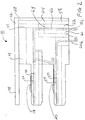
- Figure 1 is a front perspective showing of the compact shielded data connector assembly of the present invention.
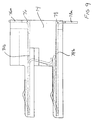
- Figure 2 is a side-plan view of the connector assembly of Figure 1.
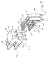
- Figure 3 shows, in exploded perspective view, components of the connector assembly of Figures 1 and 2.
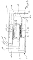
- Figure 4 shows an electrical connector of Figure 1 interconnected with a like connector in hermaphroditic fashion.
- Figure 5 is a rear-perspective view of the outer housing of the connector assembly of Figure 1.
- Figures 6 and 7 are, respectively, exploded front and rear perspective views of the insulative support member and electrical contacts of the connector assembly of Figure 1.
- Figure 8 is a perspective showing of alternative constructions of the electrical contacts of the connector assembly of Figure 1.
- Figure 9 is a side-plan view of the alternative contacts of Figure 8 supported within the terminal support member.
- Data connector assembly 10 is of the type used to transmit data signals between components of a closed-loop data system.
- Connector assembly 10 may function in hermaphroditic fashion, that is, it is interconnectable to a similarly formed electrical connector assembly, or it may function in a panel mount environment where plural such connector assemblies are supported on a wiring panel for connection with similarly formed electrical connectors.
- the connector assembly 10 of the present invention may be of the type shown and described in U.S. Patent Application Serial No. 08/013,452, filed February 4, 1993 entitled VERTICALLY ALIGNED ELECTRICAL CONNECTOR COMPONENTS, now US-A-5 405 268, which is assigned to the assignee of the present invention.
- Connector assembly 10 comprises an electrically conductive outer housing 12, a pair of side by side electrically insulative support members 14 and 16, upper and lower electrical contacts 18 and 20, respectively, an insulative rear-contact support 22 and a rear-conductive shield 24.
- Conductive outer housing 12 and conductive rear shield 24 are formed in the preferred embodiment of die-cast metal. However, other conductive elements such as conductive plastic or metalized plastic may be employed. Support members 14 and 16, as well as contact support 22, are formed of a suitably electrically insulative plastic. Electrical contacts 18 and 20 are formed of a suitably conductive metallic material such as beryllium copper.
- Outer housing 12 is generally an elongate rectangular member having a front interconnection end 26 and a rear contact accommodating end 28. Outer housing 12 is divided into four discrete compartments 30 arranged in side by side and upper and lower quadrants. Outer housing 12 includes a pair of opposed spaced-apart vertical side walls 32 and a central vertical dividing wall 34. A horizontal upper wall 38 extends across the upper extents of side walls 32 and dividing wall 34.
- Outer housing 12 further includes intermediate horizontal bridge portions 40 extending between side walls 32 and dividing wall 34, as well as lower horizontal bridge portions 42, which also extend between side walls 32 and dividing wall 34.
- the construction of outer housing 12 provides for the complete perimetrical bounding of compartments 30. It is contemplated that in the preferred embodiment, the outer housing 12 will be integrally formed. However, individual components may be used to make up outer housing 12.
- Support members 14 and 16 are preferably of identical construction.
- Support member 14 is generally an elongate molded plastic member having a rear contact accommodating end 44, a central main body portion 46 and upper and lower support platforms 48 and 50 extending oppositely from rear contact accommodating end 44.
- Support member 14 includes a pair of side by side upper channels 52 extending from rear contact accommodating end 44 through central main body portion 46 and along upper support platform 48.
- side by side lower channels 54 extend from the rear contact accommodating end 44 through central main body portion 46 and along lower support platform 50.
- Each support member 14 is divided into individual upper and lower stacked support elements 14a and 14b which include upper and lower support platforms 48 and 50, respectively.
- Figures 6 and 7 further show upper and lower electrical contacts 18 and 20 which are typically stamped and formed members.
- Lower contacts 20 include a generally elongate base portion 20a, a pin-type solder tail 20b and a reversely directed cantilevered spring portion 20c which extends back over base portion 20a.
- Solder tail 20b is of conventional construction and may be inserted into a through hole of a printed circuit board (not shown) and soldered thereto establishing electrical connection therebetween. In the present illustrative embodiment, solder tail 20b is shown extending downwardly at a right angle from base portion 20a, however, straight-solder tails may also be employed.
- Cantilevered spring portion 20c is constructed so as to be deflectable for movement toward and away from base portion 20a upon interconnection of a further connection device. Cantilevered spring portion 20c has an extended beam length which extends toward solder tail 20b.
- Upper contacts 18 are of construction similar to that of contacts 20.
- Contacts 18 include an elongate base portion 18a, a solder tail 18b and a reversely directed cantilevered spring portion 18c of length shorter than cantilevered spring portion 20c of contact 20.
- solder tail 18b of contacts 18 are longer than the solder tails 20b of contacts 20 so that the distal extents 18h and 20h of the solder tails extend approximately the same distance, facilitating connection of the solder tails to a printed circuit board.
- upper contacts 18 include a depending shunt member 18d which is struck from a central extent of planar base portion 18a.
- the distal extent 18e of shunt member 18d is engagable with the extended beam of cantilevered spring portion 20c of contacts 20 to provide for shunted engagement as between contacts 18 and 20.
- Shunt member 18d of contact 18 extends downwardly from base portion 18a at an angle just less than 90°.
- the distal extent 18e has a reversely curved portion.
- contacts 18 and 20 are supported within support member 14.
- Base portions 18a and 20a are supported respectively on platforms 48 and 50 through upper and lower channels 52 and 54.
- Solder tails 18b and 20b extend along rear contact accommodating end 44 of support member 14.
- Support members 14 and 16 supporting upper and lower contacts 18 and 20 are inserted into outer housing 12 in side by side fashion.
- Each upper and lower support platform 48 and 50 of support members 14 and 16 are individually accommodated in one of the bounded compartments 30 of outer housing 12 (Fig. 5).
- Upper wall 38, side walls 32 and lower bridge portions 42 serve to shield collectively the contact 18 and 20.
- Dividing wall 34 serves to shield each of the side by side pairs of contacts 18 and 20.
- Intermediate bridge portions 40 serve to shield the upper contacts 18 from the lower contacts 20.
- intermediate bridge portion 40 includes spaced recesses 40a separated by a central protrusion 40b.
- Shunt member 18d of each contact 18 extends through recess 40a.
- the central protrusion 40b provides shielding as between adjacent shunt member 18d.
- Shield 24 formed of conductive metal, includes a short forward wall 56 and a taller rear wall 58 separated by a centrally located transverse web 60. Shield 24 provides conductive shielding as between solder tails 18b of upper contacts 18 and solder tails 20b of lower contacts 20. This is achieved by positioning solder tail 20b on one side of forward wall 56 while solder tails 18b are positioned on the other side of forward wall 56. Solder tails 18b reside between walls 56 and 58.
- connector assembly 10 includes insulative contact support 22.
- Contact support 22 is a plastic member having a front wall 62, a taller rear wall 64 and individual chambers 66, which individually accommodate solder tails 18b of contacts 18.
- Contact support 22 includes a recess 68 extending from a lower edge thereof which accommodates web 60 of shield 24 when contact support 22 is inserted within shield 24.
- shield 24 having contact support 22 inserted therein, may be inserted over the solder tails 18b of contacts 18 to reside adjacent contact accommodating end 28 of outer housing 12.
- connector assembly 10 is shown interconnected to an identical connector 10' in hermaphroditic fashion. This is accomplished by rotating connector assembly 10' 180° and interconnecting the two parts so that upper contacts 18 of connector assembly 10 engage lower contacts 20' of connector assembly 10', while lower contacts 20 of connector assembly 10 engage upper contacts 18' of connector assembly 10'. It is noted that as the lower contacts of one connector engage the upper contacts of the other connector when connected in hermaphroditic fashion, the electrical path between each pair of the mated contacts will be the same for all contact pairs.
- the electrical path length between the tip 18h' of solder tail 18b' and the tip 20h of solder tail 20b, which is connected thereto, is the same as the path length between the tip 18h of solder tail 18b and the tip 20h' of solder tail 20b' of another connected pair of contacts.
- Cantilevered spring portions 18c and 20c of upper and lower contacts 18 and 20 further provide a first upwardly inclined contact surface 70 extending from the front end of the contacts to a centrally located apex 72.
- the contact further includes a depending rearwardly facing engagement surface 74 extending from apex 72 down to the distal end of the contacts.
- FIGs 8 an 9 Further embodiments of the present invention may be shown in Figures 8 an 9. Contacts of the present invention include solder type tails 18b and 20b such as shown in contacts 18 and 20 for attachment to through holes of a printed circuit board. However, the present invention also contemplates employing other contact types 76 and 78, which include IDC portions 76a and 78a for making insulation displacing connection to electrical conductors (not shown) in a manner described in the above-incorporated patent application. IDC portions 76a and 78a may extend at oppositely directed 90° angles from the central base portions 76b and 78b of contacts 76 and 78. Figure 9 shows such insulation displacement contacts 76 and 78 supported in a support member 14.
- connector assembly 10 of the present invention may accommodate different transmission styles within the same connector assembly. While the present embodiment shows transmission terminal devices of the electrical signal type, other terminals, such as fiber optic terminations and power contacts, may be inserted into connector assembly 10. It is further contemplated that the transmission terminal device may be the stamped end of a co-axial cable where the center conductor serves as an electrical contact. Support members 14 and 16 can be adapted to accommodate such co-axial cable. Thus, connector assembly 10 may house mixed transmission components.
Landscapes
- Details Of Connecting Devices For Male And Female Coupling (AREA)
- Coupling Device And Connection With Printed Circuit (AREA)
- Connections By Means Of Piercing Elements, Nuts, Or Screws (AREA)
Claims (8)
- Ein elektrischer Verbinder (10) miteinem elektrisch leitenden Außengehäuse (12) mit mehreren diskreten abgegrenzten Abteilen (30),elektrisch isolierten Anschlußtrageelementen (14, 16), die sämtlich in einem der abgegrenzten Abteile (30) aufgenommen sind und wobei zwei der elektrisch isolierten Anschlußtrageelemente (14, 16) in geschichteter Beziehung integral ausgebildet sind,wobei die geschichteten Anschlußtrageelemente (14, 16) Abschnitte aufweisen, die in zwei vertikal ausgerichteten abgegrenzten Abteilen (30) des Außengehäuses (12) ruhen, und mitmehreren in mindestens einem der Trageelemente (14, 16) abgestützten Übertragungsanschlußvorrichtungen (18, 20),wobei die Anschlußvorrichtungen (18, 20) des einen Trageelementes (14, 16) durch das abgegrenzte Abteil (30) von den anderen Trageelementen (14, 16) elektrisch abgeschirmt sind.
- Ein elektrischer Verbinder nach Anspruch 1, bei dem die Übertragungsanschlußvorrichtungen (18, 20) eines der Trageelemente elektrische Kontakte (18, 20) sind.
- Ein elektrischer Verbinder nach Anspruch 2, bei dem mindestens ein anderes Trageelement (14, 16) zusätzliche elektrische Kontakte (18, 20) trägt.
- Ein elektrischer Verbinder nach Anspruch 2 oder Anspruch 3, wobei jeder elektrische Kontakt (18, 20) ein Anschlußende zur elektrischen Anlage an einem Kontakt eines zu ihm passenden Verbinders und gegenüber dem Anschlußende ein Abschlußende aufweist.
- Ein elektrischer Verbinder nach Anspruch 4, wobei das Abschlußende eine stiftartige Lötfahne (18b, 20b) aufweist.
- Ein elektrischer Verbinder nach Anspruch 4, wobei das Abschlußende einen die Isolation verdrängenden Kontaktabschnitt aufweist.
- Ein elektrischer Verbinder nach irgendeinem der Ansprüche 1 bis 6, wobei das Außengehäuse (12) aus Spritzgußmetall geformt ist.
- Ein elektrischer Verbinder nach irgendeinem der Ansprüche 1 bis 7, wobei der Verbinder (10) hermaphroditisch ist.
Applications Claiming Priority (2)
| Application Number | Priority Date | Filing Date | Title |
|---|---|---|---|
| US08/092,049 US5593311A (en) | 1993-07-14 | 1993-07-14 | Shielded compact data connector |
| US92049 | 2002-03-04 |
Publications (3)
| Publication Number | Publication Date |
|---|---|
| EP0634817A2 EP0634817A2 (de) | 1995-01-18 |
| EP0634817A3 EP0634817A3 (de) | 1996-06-05 |
| EP0634817B1 true EP0634817B1 (de) | 2001-02-21 |
Family
ID=22231155
Family Applications (1)
| Application Number | Title | Priority Date | Filing Date |
|---|---|---|---|
| EP94305127A Expired - Lifetime EP0634817B1 (de) | 1993-07-14 | 1994-07-13 | Abgeschirmter kompakter Verbinder zur Datenübertragung |
Country Status (8)
| Country | Link |
|---|---|
| US (1) | US5593311A (de) |
| EP (1) | EP0634817B1 (de) |
| JP (1) | JP3419553B2 (de) |
| CA (1) | CA2127838C (de) |
| DE (1) | DE69426716T2 (de) |
| ES (1) | ES2156136T3 (de) |
| IL (1) | IL110326A (de) |
| SG (1) | SG64369A1 (de) |
Families Citing this family (56)
| Publication number | Priority date | Publication date | Assignee | Title |
|---|---|---|---|---|
| US5564949A (en) * | 1995-01-05 | 1996-10-15 | Thomas & Betts Corporation | Shielded compact data connector |
| DE19614788B4 (de) * | 1995-09-29 | 2005-12-22 | Adc Gmbh | Anschlußleiste für hohe Übertragungsraten |
| JP3095349B2 (ja) * | 1996-03-21 | 2000-10-03 | ヒロセ電機株式会社 | 電気コネクタ |
| US6135781A (en) * | 1996-07-17 | 2000-10-24 | Minnesota Mining And Manufacturing Company | Electrical interconnection system and device |
| US5762525A (en) * | 1996-08-06 | 1998-06-09 | Candeloro; Salvatore | Electrical wiring system |
| US5871368A (en) * | 1996-11-19 | 1999-02-16 | Intel Corporation | Bus connector |
| US6095826A (en) * | 1997-02-21 | 2000-08-01 | Berg Technology, Inc. | Press fit circuit board connector |
| US6086430A (en) * | 1997-02-27 | 2000-07-11 | International Business Machines Corporation | Enhanced universal serial bus |
| US6068520A (en) * | 1997-03-13 | 2000-05-30 | Berg Technology, Inc. | Low profile double deck connector with improved cross talk isolation |
| FR2762453B1 (fr) * | 1997-04-17 | 1999-06-25 | Soc D Fabrication Ind Et Mecan | Connecteur electrique pour frequences elevees |
| US5919063A (en) * | 1997-09-17 | 1999-07-06 | Berg Technology, Inc. | Three row plug and receptacle connectors with ground shield |
| KR100511537B1 (ko) * | 1997-09-17 | 2005-09-26 | 에프씨아이 | 접지 차폐부를 갖는 3개 열의 플러그 및 리셉터클 커넥터 |
| CA2275923C (en) * | 1997-10-30 | 2006-12-19 | Thomas & Betts International, Inc. | Electrical connector having an improved connector shield and a multi-purpose strain relief |
| US6077122A (en) * | 1997-10-30 | 2000-06-20 | Thomas & Bett International, Inc. | Electrical connector having an improved connector shield and a multi-purpose strain relief |
| US6113426A (en) * | 1997-11-10 | 2000-09-05 | Molex Incorporated | Connector with improved shield and terminal structure |
| US6780054B2 (en) | 1998-01-15 | 2004-08-24 | The Siemon Company | Shielded outlet having contact tails shield |
| JP2001515651A (ja) * | 1998-01-15 | 2001-09-18 | ザ シーモン カンパニー | 性能が向上した電気通信コネクタ |
| US6328601B1 (en) * | 1998-01-15 | 2001-12-11 | The Siemon Company | Enhanced performance telecommunications connector |
| US6358091B1 (en) | 1998-01-15 | 2002-03-19 | The Siemon Company | Telecommunications connector having multi-pair modularity |
| DE69911486T2 (de) * | 1998-03-05 | 2004-07-22 | Fci | Doppelreihiger Mehrfachmodularstecker mit unterdrücktem gegenseitigen Übersprechen |
| US6409547B1 (en) | 1998-12-02 | 2002-06-25 | Nordx/Cdt, Inc. | Modular connectors with compensation structures |
| US6132255A (en) * | 1999-01-08 | 2000-10-17 | Berg Technology, Inc. | Connector with improved shielding and insulation |
| ATE263444T1 (de) * | 1999-01-22 | 2004-04-15 | Siemon Co | Telekommunikationsverbinder |
| NL1012357C2 (nl) * | 1999-06-16 | 2000-12-19 | Berg Electronics Mfg | Afgeschermd connectorsamenstel. |
| EP1190470A2 (de) * | 1999-06-16 | 2002-03-27 | FCI 's-Hertogenbosch B.V. | Abgeschirmte verbinderanordnung und kontaktelement zur verwendung in einem solchen verbinder |
| US6216059B1 (en) | 1999-09-14 | 2001-04-10 | Paul Francis Ierymenko | Unitary transducer control system |
| US6859173B2 (en) * | 2001-06-21 | 2005-02-22 | The Rosum Corporation | Position location using broadcast television signals and mobile telephone signals |
| US6559800B2 (en) * | 2001-02-02 | 2003-05-06 | Rosum Corporation | Position location using broadcast analog television signals |
| US6963306B2 (en) * | 2001-02-02 | 2005-11-08 | Rosum Corp. | Position location and data transmission using pseudo digital television transmitters |
| US20050251844A1 (en) * | 2001-02-02 | 2005-11-10 | Massimiliano Martone | Blind correlation for high precision ranging of coded OFDM signals |
| US20020184653A1 (en) * | 2001-02-02 | 2002-12-05 | Pierce Matthew D. | Services based on position location using broadcast digital television signals |
| US7126536B2 (en) * | 2001-02-02 | 2006-10-24 | Rosum Corporation | Position location using terrestrial digital video broadcast television signals |
| US20050066373A1 (en) * | 2001-02-02 | 2005-03-24 | Matthew Rabinowitz | Position location using broadcast digital television signals |
| US6952182B2 (en) * | 2001-08-17 | 2005-10-04 | The Rosom Corporation | Position location using integrated services digital broadcasting—terrestrial (ISDB-T) broadcast television signals |
| US7463195B2 (en) * | 2001-06-21 | 2008-12-09 | Rosum Corporation | Position location using global positioning signals augmented by broadcast television signals |
| US7042396B2 (en) * | 2001-08-17 | 2006-05-09 | Rosom Corporation | Position location using digital audio broadcast signals |
| US6970132B2 (en) * | 2001-02-02 | 2005-11-29 | Rosum Corporation | Targeted data transmission and location services using digital television signaling |
| US6839024B2 (en) | 2001-06-21 | 2005-01-04 | Rosum Corporation | Position determination using portable pseudo-television broadcast transmitters |
| EP1281994A1 (de) * | 2001-07-30 | 2003-02-05 | Agilent Technologies, Inc. (a Delaware corporation) | Sender/Empfänger-Stecker |
| US6914560B2 (en) * | 2001-08-17 | 2005-07-05 | The Rosum Corporation | Position location using broadcast digital television signals comprising pseudonoise sequences |
| DE60208885T2 (de) | 2002-01-30 | 2006-08-31 | Fujitsu Component Ltd. | Verbinder |
| JP4190019B2 (ja) * | 2006-09-12 | 2008-12-03 | 日本航空電子工業株式会社 | コネクタ |
| JP5090055B2 (ja) * | 2007-05-07 | 2012-12-05 | 日本航空電子工業株式会社 | コネクタ |
| US7682199B2 (en) * | 2007-05-07 | 2010-03-23 | Samsung Electronics Co., Ltd. | Connector |
| US8888536B2 (en) * | 2012-06-10 | 2014-11-18 | Apple Inc. | Low profile hard-disk drive connector |
| US9065209B2 (en) | 2012-09-21 | 2015-06-23 | Thomas & Betts International, Llc | Hermaphroditic electrical connector for terminating electrical conductors |
| US9231321B2 (en) | 2012-10-22 | 2016-01-05 | Apple Inc. | Slim-profile hard-disk drive connector |
| JP2014135197A (ja) * | 2013-01-10 | 2014-07-24 | Toshiba Corp | 電子機器およびコネクタ |
| DE202013001452U1 (de) * | 2013-02-14 | 2013-03-21 | Rosenberger Hochfrequenztechnik Gmbh & Co. Kg | Adapter |
| WO2015164538A1 (en) | 2014-04-23 | 2015-10-29 | Tyco Electronics Corporation | Electrical connector with shield cap and shielded terminals |
| JP6452531B2 (ja) * | 2015-04-15 | 2019-01-16 | 日本航空電子工業株式会社 | コネクタ |
| DE102017105682A1 (de) * | 2017-03-16 | 2018-09-20 | Te Connectivity Germany Gmbh | Kontaktträger, elektrische Kontakteinrichtung sowie Verfahren zum Herstellen eines konfektionierten Kabels |
| CN110637395B (zh) * | 2017-07-18 | 2021-11-02 | 阿维科斯公司 | 板对板接触桥系统 |
| US11114796B2 (en) * | 2018-12-04 | 2021-09-07 | Carlisle Interconnect Technologies, Inc. | Electrical connector with modular housing for accommodating various contact layouts |
| DE102020133325A1 (de) * | 2020-12-14 | 2022-06-15 | Harting Electric Gmbh & Co. Kg | Leiterkartensteckverbinder mit hermaphroditischen Kontaktelementen |
| JP2024064484A (ja) * | 2022-10-28 | 2024-05-14 | ヒロセ電機株式会社 | 同型コネクタと接続可能なコネクタ装置 |
Family Cites Families (58)
| Publication number | Priority date | Publication date | Assignee | Title |
|---|---|---|---|---|
| US1345293A (en) | 1919-10-30 | 1920-06-29 | Albert C Vanerka | Window-shade carrier |
| JPS525273U (de) * | 1975-06-27 | 1977-01-14 | ||
| US4451107A (en) * | 1982-08-23 | 1984-05-29 | Amp Incorporated | High speed modular connector for printed circuit boards |
| US4501459A (en) * | 1982-12-22 | 1985-02-26 | Amp Incorporated | Electrical connector |
| US4449778A (en) * | 1982-12-22 | 1984-05-22 | Amp Incorporated | Shielded electrical connector |
| USRE32760E (en) * | 1982-12-22 | 1988-10-04 | Amp Domestic Inc. | Electrical connector |
| US4516825A (en) * | 1983-07-11 | 1985-05-14 | Stewart Stamping Corporation | Modular connector for terminating EMI/RFI shielded cordage |
| US4508415A (en) * | 1983-07-29 | 1985-04-02 | Amp Incorporated | Shielded electrical connector for flat cable |
| US4582376A (en) * | 1984-04-09 | 1986-04-15 | Amp Incorporated | Shorting bar having wiping action |
| US4571014A (en) * | 1984-05-02 | 1986-02-18 | At&T Bell Laboratories | High frequency modular connector |
| US4659163A (en) * | 1984-06-13 | 1987-04-21 | Amp Incorporated | Filtered shielded connector assembly |
| US4671599A (en) * | 1984-10-30 | 1987-06-09 | Amp Incorporated | Shielded electrical connector |
| US4641906A (en) * | 1984-10-30 | 1987-02-10 | Amp Incorporated | Shielded electrical connector |
| US4744769A (en) * | 1984-12-20 | 1988-05-17 | Amp Incorporated | Closed loop connector |
| US4602833A (en) * | 1984-12-20 | 1986-07-29 | Amp Incorporated | Closed loop connector |
| US4653825A (en) * | 1985-09-06 | 1987-03-31 | Amp Incorporated | Shielded electrical connector assembly |
| US4619494A (en) * | 1985-10-07 | 1986-10-28 | Thomas & Betts Corporation | Shielded electrical connector |
| US4682836A (en) * | 1985-10-07 | 1987-07-28 | Thomas & Betts Corporation | Electrical connector and cable termination apparatus therefor |
| US4711507A (en) * | 1985-10-07 | 1987-12-08 | Thomas & Betts Corporation | Electrical connector and latching apparatus therefor |
| US4731032A (en) * | 1986-04-09 | 1988-03-15 | Thomas & Betts Corporation | Protective cover for electrical connector |
| US4756695A (en) * | 1986-06-13 | 1988-07-12 | Amp Incorporated | Local area network interface |
| US4838811A (en) * | 1986-08-22 | 1989-06-13 | Hirose Electric Co., Ltd. | Modular connector with EMI countermeasure |
| US4824383A (en) * | 1986-11-18 | 1989-04-25 | E. I. Du Pont De Nemours And Company | Terminator and corresponding receptacle for multiple electrical conductors |
| US5169324A (en) * | 1986-11-18 | 1992-12-08 | Lemke Timothy A | Plug terminator having a grounding member |
| CA1289211C (en) * | 1986-11-18 | 1991-09-17 | Timothy A. Lemke | Terminator for multiple electrical conductors |
| US4859201A (en) * | 1986-12-22 | 1989-08-22 | Amp Incorporated | Data communications outlet |
| ES1004786Y (es) * | 1986-12-22 | 1989-04-01 | Amp Incorporated | Un conectador electrico. |
| US4711511A (en) * | 1987-01-23 | 1987-12-08 | Thomas & Betts Corporation | Latching apparatus for an electrical connector |
| JPH0436556Y2 (de) * | 1987-05-18 | 1992-08-28 | ||
| US4883433A (en) * | 1987-12-21 | 1989-11-28 | Amp Incorporated | Electrical connector for data distribution panel |
| US4846727A (en) * | 1988-04-11 | 1989-07-11 | Amp Incorporated | Reference conductor for improving signal integrity in electrical connectors |
| JPH0250983U (de) * | 1988-10-04 | 1990-04-10 | ||
| DE8813917U1 (de) * | 1988-11-07 | 1989-02-09 | Rittal-Werk Rudolf Loh Gmbh & Co Kg, 6348 Herborn | Vorrichtung zum Befestigen eines Steckers in einem Durchbruch einer Platte, eines Trägers o.dgl. |
| US4898546A (en) * | 1988-12-16 | 1990-02-06 | E. I. Du Pont De Nemours And Company | Ground plane shield device for right angle connectors |
| US5098311A (en) * | 1989-06-12 | 1992-03-24 | Ohio Associated Enterprises, Inc. | Hermaphroditic interconnect system |
| DE69018000T2 (de) * | 1989-10-10 | 1995-09-28 | Whitaker Corp | Rückwandsteckverbinder mit angepasster Impedanz. |
| US4984992A (en) * | 1989-11-01 | 1991-01-15 | Amp Incorporated | Cable connector with a low inductance path |
| US5030121A (en) * | 1990-02-13 | 1991-07-09 | Thomas & Betts Corporation | Electrical connector with contact wiping action |
| US5030114A (en) * | 1990-04-30 | 1991-07-09 | International Business Machines Corporation | Shield overcoat |
| US5052940A (en) * | 1990-05-11 | 1991-10-01 | Rit-Rad Interconnection Technologies Ltd. | Hermaphroditic self-shorting electrical connector |
| US5074803A (en) * | 1990-09-28 | 1991-12-24 | Amp Incorporated | Latching mechanism for shielded data connector |
| US5122076A (en) * | 1990-09-28 | 1992-06-16 | Amp Incorporated | Data connector locking mechanism |
| US5178554A (en) * | 1990-10-26 | 1993-01-12 | The Siemon Company | Modular jack patching device |
| US5052948A (en) * | 1990-11-19 | 1991-10-01 | Itt Corporation | Connector ground and shield |
| US5104337A (en) * | 1991-02-20 | 1992-04-14 | Chian Chyun Enterprise Co. Ltd. | Strain relief device for an electrical connector |
| US5112243A (en) * | 1991-02-20 | 1992-05-12 | Chian Chyun Enterprise Co. Ltd. | Latching device for an electrical connector |
| US5088934A (en) * | 1991-02-20 | 1992-02-18 | Chian Chyun Enterprise Co. Ltd. | Electrical terminal |
| US5190464A (en) * | 1991-03-29 | 1993-03-02 | Chian Chyun Enterprise Co. Ltd. | Shielded electrical connector with contact shunting arrangement |
| JPH04328286A (ja) * | 1991-04-25 | 1992-11-17 | Dai Ichi Denshi Kogyo Kk | 電気コネクタ |
| JPH04135184U (ja) * | 1991-06-06 | 1992-12-16 | 東洋電装株式会社 | リセプタクル |
| US5160273A (en) * | 1991-06-24 | 1992-11-03 | Porta Systems Corp. | Connector block assembly |
| JPH0521110A (ja) * | 1991-07-10 | 1993-01-29 | Amp Japan Ltd | シールド型電気コネクタ |
| US5190479A (en) * | 1991-09-30 | 1993-03-02 | Honeywell Inc. | Electrical connector incorporating EMI/RFI/EMP isolation |
| US5169346A (en) * | 1991-12-04 | 1992-12-08 | Johnston James J | Data connector/modular jack adapter and method for making |
| US5328380A (en) * | 1992-06-26 | 1994-07-12 | Porta Systems Corp. | Electrical connector |
| US5487682A (en) * | 1992-09-08 | 1996-01-30 | The Whitaker Corporation | Shielded data connector |
| US5405268A (en) * | 1993-02-04 | 1995-04-11 | Thomas & Betts Corporation | Vertically aligned electrical connector components |
| US5376021A (en) * | 1993-02-05 | 1994-12-27 | Thomas & Betts Corporation | Enhanced performance data connector |
-
1993
- 1993-07-14 US US08/092,049 patent/US5593311A/en not_active Expired - Lifetime
-
1994
- 1994-07-12 CA CA002127838A patent/CA2127838C/en not_active Expired - Lifetime
- 1994-07-13 ES ES94305127T patent/ES2156136T3/es not_active Expired - Lifetime
- 1994-07-13 SG SG1996008958A patent/SG64369A1/en unknown
- 1994-07-13 DE DE69426716T patent/DE69426716T2/de not_active Expired - Lifetime
- 1994-07-13 EP EP94305127A patent/EP0634817B1/de not_active Expired - Lifetime
- 1994-07-14 IL IL11032694A patent/IL110326A/en not_active IP Right Cessation
- 1994-07-14 JP JP16252694A patent/JP3419553B2/ja not_active Expired - Lifetime
Also Published As
| Publication number | Publication date |
|---|---|
| US5593311A (en) | 1997-01-14 |
| IL110326A (en) | 1999-03-12 |
| CA2127838C (en) | 2004-06-29 |
| EP0634817A2 (de) | 1995-01-18 |
| JP3419553B2 (ja) | 2003-06-23 |
| DE69426716T2 (de) | 2001-06-13 |
| EP0634817A3 (de) | 1996-06-05 |
| SG64369A1 (en) | 1999-04-27 |
| IL110326A0 (en) | 1994-10-21 |
| DE69426716D1 (de) | 2001-03-29 |
| ES2156136T3 (es) | 2001-06-16 |
| JPH07147171A (ja) | 1995-06-06 |
| CA2127838A1 (en) | 1995-01-15 |
Similar Documents
| Publication | Publication Date | Title |
|---|---|---|
| EP0634817B1 (de) | Abgeschirmter kompakter Verbinder zur Datenübertragung | |
| EP0735612B1 (de) | Elektrischer Verbinder mit verbesserter Leiterhalterung und Schirmung | |
| US5564949A (en) | Shielded compact data connector | |
| EP0635910B1 (de) | Elektrischer Steckverbinder | |
| US7104843B2 (en) | Receptacle | |
| EP0635905B1 (de) | Elektrischer Erdungsverbinder | |
| EP1717912B1 (de) | Elektrischer Verbinder mit niedrigem Übersprechen und gesteuertem Impedanzverhalten | |
| US6893270B2 (en) | Paddle-card termination for shielded cable | |
| US4976628A (en) | Modules for cable assemblies | |
| EP0853352A2 (de) | Elektrische Steckverbinder | |
| EP0658953A2 (de) | Anordnung von modularen Steckern mit einer Mehrzahl von Öffnungen | |
| EP0624928B1 (de) | Abgeschirmte elektrische Verbinderanordnung | |
| US5971812A (en) | Modular plug having a circuit board | |
| US6918774B2 (en) | Electrical connector having long circuit boards | |
| EP0614248B1 (de) | Schnittstelle für ein lokales Netz (LAN) | |
| US4537459A (en) | Jack for EMI/RFI shield terminating modular plug connector | |
| US5790660A (en) | Shunted modular jack | |
| EP0641043B1 (de) | Abgeschirmter kompakter Datenverbinder | |
| US6375506B1 (en) | High-density high-speed input/output connector | |
| EP0476883B1 (de) | Elektrische Steckverbinderanordnung | |
| EP0634816A1 (de) | Vertikal ausgerichtete elektrische abgeschirmte Verbinderbauteile | |
| US4506940A (en) | Input/output intercard connector | |
| US4772211A (en) | Multi-plane interconnection system |
Legal Events
| Date | Code | Title | Description |
|---|---|---|---|
| PUAI | Public reference made under article 153(3) epc to a published international application that has entered the european phase |
Free format text: ORIGINAL CODE: 0009012 |
|
| AK | Designated contracting states |
Kind code of ref document: A2 Designated state(s): BE CH DE ES FR GB IT LI LU NL SE |
|
| PUAL | Search report despatched |
Free format text: ORIGINAL CODE: 0009013 |
|
| AK | Designated contracting states |
Kind code of ref document: A3 Designated state(s): BE CH DE ES FR GB IT LI LU NL SE |
|
| 17P | Request for examination filed |
Effective date: 19961119 |
|
| 17Q | First examination report despatched |
Effective date: 19980921 |
|
| GRAG | Despatch of communication of intention to grant |
Free format text: ORIGINAL CODE: EPIDOS AGRA |
|
| 17Q | First examination report despatched |
Effective date: 19980921 |
|
| GRAG | Despatch of communication of intention to grant |
Free format text: ORIGINAL CODE: EPIDOS AGRA |
|
| GRAH | Despatch of communication of intention to grant a patent |
Free format text: ORIGINAL CODE: EPIDOS IGRA |
|
| GRAH | Despatch of communication of intention to grant a patent |
Free format text: ORIGINAL CODE: EPIDOS IGRA |
|
| RAP1 | Party data changed (applicant data changed or rights of an application transferred) |
Owner name: THOMAS & BETTS CORPORATION (A TENNESSEE CORPORATIO |
|
| RIC1 | Information provided on ipc code assigned before grant |
Free format text: 7H 01R 24/00 A, 7H 01R 13/658 B |
|
| GRAA | (expected) grant |
Free format text: ORIGINAL CODE: 0009210 |
|
| AK | Designated contracting states |
Kind code of ref document: B1 Designated state(s): BE CH DE ES FR GB IT LI LU NL SE |
|
| REG | Reference to a national code |
Ref country code: CH Ref legal event code: NV Representative=s name: BOVARD AG PATENTANWAELTE Ref country code: CH Ref legal event code: EP |
|
| REF | Corresponds to: |
Ref document number: 69426716 Country of ref document: DE Date of ref document: 20010329 |
|
| ET | Fr: translation filed | ||
| ITF | It: translation for a ep patent filed | ||
| REG | Reference to a national code |
Ref country code: ES Ref legal event code: FG2A Ref document number: 2156136 Country of ref document: ES Kind code of ref document: T3 |
|
| PLBE | No opposition filed within time limit |
Free format text: ORIGINAL CODE: 0009261 |
|
| STAA | Information on the status of an ep patent application or granted ep patent |
Free format text: STATUS: NO OPPOSITION FILED WITHIN TIME LIMIT |
|
| REG | Reference to a national code |
Ref country code: GB Ref legal event code: IF02 |
|
| 26N | No opposition filed | ||
| NLS | Nl: assignments of ep-patents |
Owner name: THOMAS & BETTS INTERNATIONAL, INC. |
|
| REG | Reference to a national code |
Ref country code: CH Ref legal event code: PUE Owner name: THOMAS & BETTS CORPORATION (A TENNESSEE CORPORATIO Ref country code: CH Ref legal event code: PFA Free format text: THOMAS & BETTS CORPORATION (A TENNESSEE CORPORATION) TRANSFER- THOMAS & BETTS CORPORATION (A TENNESSEE CORPORATION) |
|
| NLS | Nl: assignments of ep-patents |
Owner name: THOMAS & BETTS INTERNATIONAL, INC. |
|
| REG | Reference to a national code |
Ref country code: CH Ref legal event code: PFA Owner name: THOMAS & BETTS INTERNATIONAL, INC. (A DELAWARE CO Free format text: THOMAS & BETTS INTERNATIONAL, INC. (A DELAWARE CORPORATION)#250 LILLARD DRIVE#SPARKS, NEVADA 89434 (US) -TRANSFER TO- THOMAS & BETTS INTERNATIONAL, INC. (A DELAWARE CORPORATION)#250 LILLARD DRIVE#SPARKS, NEVADA 89434 (US) |
|
| PGFP | Annual fee paid to national office [announced via postgrant information from national office to epo] |
Ref country code: LU Payment date: 20130730 Year of fee payment: 20 |
|
| PGFP | Annual fee paid to national office [announced via postgrant information from national office to epo] |
Ref country code: SE Payment date: 20130729 Year of fee payment: 20 Ref country code: DE Payment date: 20130729 Year of fee payment: 20 Ref country code: NL Payment date: 20130726 Year of fee payment: 20 Ref country code: CH Payment date: 20130729 Year of fee payment: 20 Ref country code: BE Payment date: 20130729 Year of fee payment: 20 Ref country code: ES Payment date: 20130726 Year of fee payment: 20 |
|
| PGFP | Annual fee paid to national office [announced via postgrant information from national office to epo] |
Ref country code: GB Payment date: 20130729 Year of fee payment: 20 Ref country code: FR Payment date: 20130717 Year of fee payment: 20 |
|
| PGFP | Annual fee paid to national office [announced via postgrant information from national office to epo] |
Ref country code: IT Payment date: 20130724 Year of fee payment: 20 |
|
| REG | Reference to a national code |
Ref country code: DE Ref legal event code: R071 Ref document number: 69426716 Country of ref document: DE Ref country code: CH Ref legal event code: PL |
|
| REG | Reference to a national code |
Ref country code: NL Ref legal event code: V4 Effective date: 20140713 |
|
| BE20 | Be: patent expired |
Owner name: *THOMAS & BETTS CORP. (A TENNESSEE CORP.) Effective date: 20140713 |
|
| REG | Reference to a national code |
Ref country code: GB Ref legal event code: PE20 Expiry date: 20140712 |
|
| REG | Reference to a national code |
Ref country code: SE Ref legal event code: EUG |
|
| REG | Reference to a national code |
Ref country code: ES Ref legal event code: FD2A Effective date: 20141007 |
|
| PG25 | Lapsed in a contracting state [announced via postgrant information from national office to epo] |
Ref country code: DE Free format text: LAPSE BECAUSE OF EXPIRATION OF PROTECTION Effective date: 20140715 |
|
| PG25 | Lapsed in a contracting state [announced via postgrant information from national office to epo] |
Ref country code: GB Free format text: LAPSE BECAUSE OF EXPIRATION OF PROTECTION Effective date: 20140712 |
|
| PG25 | Lapsed in a contracting state [announced via postgrant information from national office to epo] |
Ref country code: ES Free format text: LAPSE BECAUSE OF EXPIRATION OF PROTECTION Effective date: 20140714 |