EP0634813B1 - Distribution block - Google Patents
Distribution block Download PDFInfo
- Publication number
- EP0634813B1 EP0634813B1 EP94106797A EP94106797A EP0634813B1 EP 0634813 B1 EP0634813 B1 EP 0634813B1 EP 94106797 A EP94106797 A EP 94106797A EP 94106797 A EP94106797 A EP 94106797A EP 0634813 B1 EP0634813 B1 EP 0634813B1
- Authority
- EP
- European Patent Office
- Prior art keywords
- contact
- distributor strip
- conductor
- strip according
- current bar
- Prior art date
- Legal status (The legal status is an assumption and is not a legal conclusion. Google has not performed a legal analysis and makes no representation as to the accuracy of the status listed.)
- Expired - Lifetime
Links
- 239000004020 conductor Substances 0.000 claims abstract description 91
- 239000003999 initiator Substances 0.000 claims description 25
- 238000003780 insertion Methods 0.000 claims description 11
- 230000037431 insertion Effects 0.000 claims description 11
- 238000010276 construction Methods 0.000 description 3
- 238000004519 manufacturing process Methods 0.000 description 3
- 229910000679 solder Inorganic materials 0.000 description 3
- 230000005540 biological transmission Effects 0.000 description 2
- 239000011324 bead Substances 0.000 description 1
- 238000005452 bending Methods 0.000 description 1
- 238000010586 diagram Methods 0.000 description 1
- 230000005611 electricity Effects 0.000 description 1
- 238000009434 installation Methods 0.000 description 1
- 239000011810 insulating material Substances 0.000 description 1
- 238000000034 method Methods 0.000 description 1
- 125000006850 spacer group Chemical group 0.000 description 1
- 230000007704 transition Effects 0.000 description 1
Images

Classifications
-
- H—ELECTRICITY
- H01—ELECTRIC ELEMENTS
- H01R—ELECTRICALLY-CONDUCTIVE CONNECTIONS; STRUCTURAL ASSOCIATIONS OF A PLURALITY OF MUTUALLY-INSULATED ELECTRICAL CONNECTING ELEMENTS; COUPLING DEVICES; CURRENT COLLECTORS
- H01R9/00—Structural associations of a plurality of mutually-insulated electrical connecting elements, e.g. terminal strips or terminal blocks; Terminals or binding posts mounted upon a base or in a case; Bases therefor
- H01R9/22—Bases, e.g. strip, block, panel
- H01R9/24—Terminal blocks
- H01R9/26—Clip-on terminal blocks for side-by-side rail- or strip-mounting
- H01R9/2675—Electrical interconnections between two blocks, e.g. by means of busbars
Definitions
- the invention relates to a distribution strip with a plurality of side-by-side, Conductor connections comprising conductor rail pieces according to the preamble of the claim 1.
- Distribution strips of the generic type are used for supply and control-related connection of electrical components such as Voltage sources and signal receivers used. You can use it for this purpose used, for example, to build initiator terminal blocks be, as set out for example in EP 0 222 030 A2. In this reference is carried out that the supply lines of a voltage source two distribution strips located in an initiator terminal block and the supply voltage from there via internal cross-connection strips distributed over several connecting terminals arranged side by side to which in turn supply lines, for example from initiators for electrical Signal receivers can be connected. Building the for this application distribution strips used is relatively complex, since between the Busbar pieces of the conductor connections and the components for the actual Cross distribution of electrical power additional components such as Spacers must be available, with each current transition between the components naturally have a contact resistance.
- the object of the present invention is therefore to provide a distributor strip of the generic type To create kind in which the transverse distribution of the electrical power with conceivably low design and assembly costs, especially to achieve the smallest row widths to ensure more compact Types of conductor connections is important.
- the solution according to the invention consists in the spatial assignment of the functional elements the conductor rail pieces and the arrangement of the functional areas of the Busbar pieces within the conductor connections, primarily related to the Direction of the individual conductor connections.
- the track parts consist of a first section of two lateral, opposite and central via a connecting plate U-shaped spring contact legs, on one side of the connecting plate at its free ends the socket contact form.
- a connection level formed for inserting a conductor into the conductor connection, the Connection level, the connecting plate and the socket contact essentially perpendicular to the direction of connection of the conductor connections in a spatial row one above the other are arranged.
- the spring contact legs form with the connecting plate a structural unit, the main extension of the spring contact legs perpendicular is aligned with the direction of connection of the conductor connections.
- the plug contact elements form the side by side stringing of Conductor connections to a distribution strip by locking a plug contact in a socket contact automatically an electrical connection, so that an additional Check during assembly to ensure that all cross connections of the Cross distribution have been produced.
- the plug connection of the busbar pieces of the individual conductor connections these can be made into distribution strips any length, that is, join any number of conductor connections.
- distribution strips can be set up for any purpose, which in turn for example for the construction of initiator terminal blocks with any number of poles Find use.
- the space required can be due to the arrangement of the track pieces reduce significantly perpendicular to the direction of the row, since the connector tabs a plug contact element directly between the essentially on both sides the insertion space of the socket contact arranged spring contact leg intervention.
- the conductor to be connected to the conductor connection is, for example, via a clamping spring directly with the associated section of the busbar piece of the corresponding conductor connection. Plug and socket contact are thus made in one piece, which lowers the manufacturing costs and simplifies assembly. Since the connection level of the conductor connection is easily accessible from above is, in addition to the connection option already mentioned, via a clamping spring also realize all other usual types of connection of the conductor connection.
- the direction of insertion of the conductors lies contacts in the conductor connections and the plug-in spaces of the sockets essentially in a plane that is perpendicular to the direction of connection of the conductor connections is aligned.
- the connector tab is on the free End of a spring contact leg of a busbar piece parallel to it Arranged end edge, the connector tab in the direction of the opposite Spring contact leg is cranked so that its median plane with the middle between the middle plane located between the two spring contact legs.
- the plug tab from one of the spring contact legs be bent by simple bending operations, which in turn is better Contact behavior and lower assembly costs ensures.
- one of the plug contact elements as a socket contact offers the possibility of the socket part from several directions, for example from the side or to contact from below. Because the socket contact of the first conductor connection a distribution strip for the connection to the next track or to If the structure of the total conductor rail is not required, there is the option here to a printed circuit board arranged under the conductor connections if necessary to create additional connection possibility.
- the socket contact of the individual track piece both from below and which is also accessible from the side can be fed into the distribution strip for power supply
- Arrange additional contact surfaces on the socket contact, both in the Engage the socket contact as well as on the side of the outer surface of the socket contact can make an electrical connection, as is a U-shaped Cable contact for making electrical connections at the socket contact possible.
- the fork-shaped contact has the advantage that a current feed can in principle be done at any point on the distributor strip from below. Especially With limited space, a special feed terminal can be used save on.
- an initiator terminal block provides that two distribution strips in one Basic housing of an initiator terminal block, which can be fixed on the mounting rail is arranged.
- the connection to the basic housing is made using detachable plug-in attachments, so that the distributor strips are easy and easy to install in the initiator terminal block can be regrouped.
- Possibilities of an advantageous simple coding of the invention Distribution strip in particular the often necessary grounding of Busbar connections appear very easy to implement. Because of the accessibility the busbar pieces from below is a connection of the distribution strip to the the mounting rail carrying the earth potential can be implemented without problems.
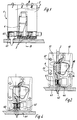
- FIG. 1 shows a distributor strip, designated in its entirety by 1, which consists of three side-by-side conductor connections labeled I-III 2 exists.
- a conductor rail piece is located in the housing 10 of each conductor connection 4, which each interlock with the aid of their plug contact elements 5.
- the structure of a conductor connection 2 is illustrated with the aid of the sectional diagram in FIG. 2.
- the busbar piece 4 In the middle of the conductor connection housing 10 there is in turn the busbar piece 4 recognizable.
- a clamping spring 14 is arranged, which serves the conductor 3 from above into the insertion funnel Introduce 13 of the conductor connection housing 10, under the busbar piece 4 to pull and fix there by clamping spring force.
- At the top of the conductor connection housing 10 is located on the side next to the insertion funnel 13 an assembly opening 15 through which an actuation of the clamping spring 14 for the Assembly process of the conductor 3 is possible.
- Each conductor connection housing has a side wall connecting cams 12 in position and size with corresponding Connection bores 11 on the opposite side surface of the conductor connection housing 10 corresponds, so that when connecting conductor connections in a row 2 these together by the engagement of the connecting cams 12 in the corresponding connection bores 11 of the adjacent conductor connection 2 are set.
- Each busbar piece 4 has a U-shaped base body 21, which consists of two spring contact legs 23 and 24 and a connecting plate 25 connecting them.
- the clamping spring 14 is shown on the outside of the spring contact leg 24 is attached. It has on its holding tab 22 facing Side an opening 30 and is shaped so that it has a spring force in the direction of the arrow F is generated. Since the retaining tab 22 protrudes through the opening 30, the Movement of the free leg 32 of the clamping spring 14 in the direction of arrow F is limited. If a counterforce is exerted on the edge 31 of the clamping spring 14, then her free leg 32 moves with the opening 30 against the arrow F downwards, so that in the interior of the U-shaped base body 21 of the busbar piece 4 a connecting wire can be inserted.
- FIGS. 1 and 2 is a way of contacting the busbar from the underside of conductor connection 2 via the socket contact 26 shown.
- the exemplary embodiment shows a solder contact 42, which is electrically connected to a circuit board 41 and on its the circuit board 41 opposite end has a contact plate 43 which through an opening 44th at the bottom of the conductor connection housing 10 in the socket contact 26 of the Busbar piece 4 engages.
- a solder contact 42 which is electrically connected to a circuit board 41 and on its the circuit board 41 opposite end has a contact plate 43 which through an opening 44th at the bottom of the conductor connection housing 10 in the socket contact 26 of the Busbar piece 4 engages.
- FIG. 4 shows a possibility of contacting the socket 26 to reach around on the outside by a fork contact 40.
- the fork contact 40 is electrically connected to a circuit board 41 like the solder contact 42 described above and engages from below the sockets contact 26, the conductor connection housing 10 in this case an adequately dimensioned cutout 45 on its Has underside.
- a distributor 1 attack if the corresponding cutout 45 in the conductor connection housing 10 Inclusion of the fork parts of the contact encompassing the contacts 26 on the side 40 is present.
- a distribution strip of the type according to the invention can thus be Position as desired over a fork contact 40 arranged in a printed circuit board 41.
- a fork contact 40 arranged in a printed circuit board 41.
- an otherwise necessary feed connection is eliminated, what is particularly advantageous when space is limited.
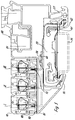
- Initiator terminal blocks are commonly used made up of individual initiator terminal blocks, in FIG. 5 is an example an initiator terminal block in cross section with three distribution strips according to the invention belonging conductor connections 2 shown.
- An initiator terminal block sets initiator terminal blocks arranged side by side perpendicular to the plane of the drawing 50 together, perpendicular to the plane of the drawing shown with each other are fixed on a common standardized mounting rail 54.
- Through the Lining up the initiator terminal blocks 50 inevitably also results a series of individual conductor connections 2 to distribution strips, which in Figure 5 are designated 1, II and III.
- the initiator series terminal 50 has one Terminal housing 51 made of insulating material, which with detachable webs 80 for detachable Fixing the conductor connection housing 10 provided in the terminal housing 51 is. These receiving webs 80 have small beads 81 which correspond to Engage recesses 82 of the conductor connection housing. Because of this design ensures that the conductor connections 2 are interchanged within a terminal block can be to z. B. convert a PNP arrangement into an NPN arrangement.
- the busbars of the individual distribution strips I, II and III offer when in use in initiator terminal blocks, of course, the possibility of contacting from the underside of the conductor connection housing 10.
- Figure 5 with the help of such Contacting a connection of the busbar of the distribution strip 3 with the Carrier rail 54 shown to build a PE distribution strip.
- the connection is made through the contact bracket 58, through the insertion funnel 53 of the conductor housing 10 engages in a socket contact of the busbar of the distribution strip 3. Since the Contact bracket 58 penetrates contact in the sockets, the contact must necessarily at the beginning of the distribution strip, as there is a free socket contact here is.
- the contact bracket 58 is riveted to a transmission plate 59 which in Initiator terminal housing 51 is fixed and touches the mounting rail 54, so that the appropriate electrical connection is established.
- the definition of the initiator terminal housing 51 on the mounting rail 54 is usually done by two housing feet 56 and 57, the angled holding leg 61 of the mounting rail 54 reach around.
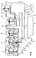
- an initiator terminal block is shown in which the switching state of the Initiator is displayed via a control LED 70.
- the contact plate 72 is part of a contact angle 71 that over a wire bridge 73 and a resistor 74 is connected to the control LED 70.
- the contact plate 72 is not like that in FIG. 5 described contact bracket 58 in the middle of a socket contact the busbar Distribution strip engages, but one of the spring contact legs of the socket contact 26 touched on the side.
- the contact plate 72 is via the insertion funnel 76 so positively driven that a contact other than the side contact of the socket contact not possible.
Landscapes
- Connections Arranged To Contact A Plurality Of Conductors (AREA)
- Ceramic Products (AREA)
- Coupling Device And Connection With Printed Circuit (AREA)
- Crystals, And After-Treatments Of Crystals (AREA)
- Connector Housings Or Holding Contact Members (AREA)
Abstract
Description
Die Erfindung betrifft eine Verteilerleiste mit mehreren, nebeneinander anreihbaren, Stromschienenstücke beinhaltenden Leiteranschlüssen gemäß Oberbegriff des Anspruches 1.The invention relates to a distribution strip with a plurality of side-by-side, Conductor connections comprising conductor rail pieces according to the preamble of the claim 1.
Verteilerleisten der gattungsgemäßen Art werden zur versorgungstechnischen und steuerungstechnischen Verknüpfung von elektrischen Bauteilen wie beispielsweise Spannungsquellen und Signalempfänger eingesetzt. Sie können für diesen Anwendungszweck beispielsweise zum Aufbau von Initiatorklemmenblöcken verwendet werden, wie dies beispielsweise in der EP 0 222 030 A2 dargelegt ist. In dieser Literaturstelle wird ausgeführt, daß die Versorgungsleitungen einer Spannungsquelle an zwei in einem Initiatorklemmenblock befindlichen Verteilerleisten angeschlossen werden und die Versorgungsspannung von dort über innenliegende Querverbindungsleisten auf mehrere nebeneinander angeordnete Anschlußklemmen verteilt wird, an die wiederum Versorgungsleitungen beispielsweise von Initiatoren für elektrische Signalempfänger angeschlossen werden. Der Aufbau der für diesen Anwendungszweck verwendeten Verteilerleisten ist relativ aufwendig, da zwischen den Stromschienenstücken der Leiteranschlüsse und den Bauteilen für die eigentliche Querverteilung der elektrischen Leistung zusätzliche Bauteile wie beispielsweise Distanzhülsen vorhanden sein müssen, wobei sich bei jedem Stromübergang zwischen den Bauteilen natürlich ein Übergangswiderstand ergibt.Distribution strips of the generic type are used for supply and control-related connection of electrical components such as Voltage sources and signal receivers used. You can use it for this purpose used, for example, to build initiator terminal blocks be, as set out for example in EP 0 222 030 A2. In this reference is carried out that the supply lines of a voltage source two distribution strips located in an initiator terminal block and the supply voltage from there via internal cross-connection strips distributed over several connecting terminals arranged side by side to which in turn supply lines, for example from initiators for electrical Signal receivers can be connected. Building the for this application distribution strips used is relatively complex, since between the Busbar pieces of the conductor connections and the components for the actual Cross distribution of electrical power additional components such as Spacers must be available, with each current transition between the components naturally have a contact resistance.
Eine Weiterbildung gattungsgemäßer Leiteranschlüsse zeigt die US-PS 4 469 128, bei der die Leiteranschlüsse Steckkontaktelemente beinhalten, die jeweils eine Steckerlasche und einen Buchsen kontakt aufweisen, wobei jeweils die Steckerlasche zur Querverteilung elektrischer Leistung in den Buchsen kontakt eines benachbarten Stromschienenstückes eingreift. Der Buchsen kontakt ist aus einer im wesentlichen U-förmigen Anordnung von Stromschienenstücken gebildet, wobei die Steckrichtung von Buchsenkontakt und zugeordneter Steckerlasche, die das Gehäuse des benachbart angeordneten Leiteranschlusses überragt, parallel zur Anreihrichtung der Leiteranschlüsse ausgebildet ist. Auf die als Basis bezeichneten Leiteranschlüsse ist von oben her in zugeordnete Stromschienenstücke ein zur Steuerung von Druckluftströmen geeignetes Ventil aufsteckbar und mit zugeordneten Steckelementen elektrisch verbindbar.A further development of generic conductor connections is shown in US Pat. No. 4,469,128, where the conductor connections contain plug contact elements, each one Have plug tab and a socket contact, each with the plug tab for transverse distribution of electrical power in the sockets contact an adjacent one Busbar piece engages. The socket contact is made of a substantially U-shaped Arrangement of busbar pieces formed, the direction of insertion of socket contact and assigned connector tab, which the housing of the adjacent arranged conductor connection protrudes, parallel to the direction of connection of the conductor connections is trained. On the conductor connections referred to as the base is from above in assigned busbar pieces to control compressed air flows suitable valve can be plugged on and with associated plug-in elements electrically connectable.
Aufgabe der vorliegenden Erfindung ist es daher, eine Verteilerleiste der gattungsgemäßen Art zu schaffen, bei der die Querverteilung der elektrischen Leistung mit denkbar geringem konstruktiven und montagemäßigen Aufwand erfolgt, wobei insbesondere auf die Erzielung geringster Reihungsbreiten für die Gewährleistung kompakter Bauformen der Leiteranschlüsse Wert gelegt wird.The object of the present invention is therefore to provide a distributor strip of the generic type To create kind in which the transverse distribution of the electrical power with conceivably low design and assembly costs, especially to achieve the smallest row widths to ensure more compact Types of conductor connections is important.
Die erfindungsgemäße Lösung ergibt sich aus den kennzeichnenden Merkmalen des Anspruches 1 im Zusammenwirken mit den Merkmalen des Oberbegriffes.The solution according to the invention results from the characterizing features of Claim 1 in cooperation with the features of the preamble.
Die erfindungsgemäße Lösung besteht in der räumlichen Zuordnung der Funktionselemente der Stromschienenstücke sowie der Anordnung der Funktionsbereiche der Stromschienenstücke innerhalb der Leiteranschlüsse, vornehmlich bezogen auf die Anreihrichtung der einzelnen Leiteranschlüsse. Die Stromschienenstücke bestehen in einem ersten Abschnitt aus je zwei seitlichen, sich gegenüberliegenden und zentral über ein Verbindungsblech U-förmig miteinander verbundenen Federkontaktschenkeln, die an einer Seite des Verbindungsbleches an ihren freien Enden den Buchsenkontakt bilden. In einem zweiten Abschnitt der Stromschienenstücke an der dem Buchsenkontakt gegenüberliegenden Seite des Verbindungsbleches ist eine Anschlußebene zum Einstecken eines Leiters in den Leiteranschluß gebildet, wobei die Anschlußebene, das Verbindungsblech sowie der Buchsen kontakt im wesentlichen senkrecht zur Anreihrichtung der Leiteranschlüsse in räumlicher Reihung übereinander angeordnet sind. Die Federkontaktschenkel bilden mit dem Verbindungsblech eine Baueinheit, wobei die Haupterstreckung der Federkontaktschenkel senkrecht zur Anreihrichtung der Leiteranschlüsse ausgerichtet ist. Hierdurch ist die Baugröße der Stromschienenstücke in Anreihrichtung der Leiteranschlüsse sehr gering auslegbar, da sowohl die Federkontaktschenkel als auch das Verbindungsblech sowie der auf der anderen Seite des Verbindungsbleches angeordnete Abschnitt als Anschlußebene für die Leiteranschlüsse im wesentlichen senkrecht zur Anreihrichtung angeordnet sind. Dies bedingt eine etwas größere Bauhöhe der Leiteranschlüsse, wodurch jedoch gleichzeitig eine sehr geringe Reihungsbreite der Leiteranschlüsse erzielbar ist. Die Steckkontaktelemente bilden beim seitlichen Aneinanderreihen der Leiteranschlüsse zu einer Verteilerleiste durch Verrastung eines Steckkontaktes in einem Buchsenkontakt automatisch eine elektrische Verbindung, so daß eine zusätzliche Kontrolle bei der Montage dahingehend entfällt, ob alle Querverbindungen der Querverteilung hergestellt worden sind. Durch die Steckkontaktierung der Stromschienenstücke der einzelnen Leiteranschlüsse lassen sich diese zu Verteilerleisten beliebiger Länge, das heißt beliebiger Leiteranschlußzahl zusammenfügen. Hierdurch lassen sich Verteilerleisten für jeden Verwendungszweck aufbauen, die wiederum beispielsweise für den Aufbau von Initiatorklemmenblöcken beliebiger Polzahl Verwendung finden. Der Platzbedarf läßt sich aufgrund der Anordnung der Stromschienenstücke senkrecht zur Anreihrichtung erheblich reduzieren, da die Steckerlaschen eines Steckkontaktelementes direkt zwischen die im wesentlichen beidseitig des Einsteckraumes des Buchsenkontaktes angeordneten Federkontaktschenkel eingreifen. Der mit dem Leiteranschluß zu verbindende Leiter wird zum Beispiel über eine Klemmfeder direkt mit dem zugehörigen Abschnitt des Stromschienenstückes des entsprechenden Leiteranschlusses verbunden. Stecker und Buchsenkontakt sind somit einstückig ausgeführt, was die Herstellungskosten senkt und die Montage vereinfacht. Da die Anschlußebene des Leiteranschlusses von oben sehr gut zugänglich ist, lassen sich außer der bereits erwähnten Anschlußmöglichkeit über eine Klemmfeder auch alle anderen üblichen Anschlußarten des Leiteranschlusses verwirklichen.The solution according to the invention consists in the spatial assignment of the functional elements the conductor rail pieces and the arrangement of the functional areas of the Busbar pieces within the conductor connections, primarily related to the Direction of the individual conductor connections. The track parts consist of a first section of two lateral, opposite and central via a connecting plate U-shaped spring contact legs, on one side of the connecting plate at its free ends the socket contact form. In a second section of the busbar pieces on the Socket contact opposite side of the connecting plate is a connection level formed for inserting a conductor into the conductor connection, the Connection level, the connecting plate and the socket contact essentially perpendicular to the direction of connection of the conductor connections in a spatial row one above the other are arranged. The spring contact legs form with the connecting plate a structural unit, the main extension of the spring contact legs perpendicular is aligned with the direction of connection of the conductor connections. This is the size the conductor rail sections can be designed to be very small in the direction of connection of the conductor connections, since both the spring contact leg and the connecting plate as well the section arranged on the other side of the connecting plate as the connection plane for the conductor connections, essentially perpendicular to the direction of baying are arranged. This necessitates a somewhat larger overall height of the conductor connections, however, this also means that the conductor connections have a very small row width is achievable. The plug contact elements form the side by side stringing of Conductor connections to a distribution strip by locking a plug contact in a socket contact automatically an electrical connection, so that an additional Check during assembly to ensure that all cross connections of the Cross distribution have been produced. Through the plug connection of the busbar pieces of the individual conductor connections, these can be made into distribution strips any length, that is, join any number of conductor connections. Hereby distribution strips can be set up for any purpose, which in turn for example for the construction of initiator terminal blocks with any number of poles Find use. The space required can be due to the arrangement of the track pieces reduce significantly perpendicular to the direction of the row, since the connector tabs a plug contact element directly between the essentially on both sides the insertion space of the socket contact arranged spring contact leg intervention. The conductor to be connected to the conductor connection is, for example, via a clamping spring directly with the associated section of the busbar piece of the corresponding conductor connection. Plug and socket contact are thus made in one piece, which lowers the manufacturing costs and simplifies assembly. Since the connection level of the conductor connection is easily accessible from above is, in addition to the connection option already mentioned, via a clamping spring also realize all other usual types of connection of the conductor connection.
In einer besonders bevorzugten Ausführungsform liegen die Einsteckrichtung der Leiter in den Leiteranschlüssen sowie die Einsteckräume der Buchsen kontakte im wesentlichen in einer Ebene, die senkrecht zur Anreihrichtung der Leiteranschlüsse ausgerichtet ist. Hierdurch kann das benötigte Mindestmaß der Reihung der Leiteranschlüsse sehr gering ausgelegt werden.In a particularly preferred embodiment, the direction of insertion of the conductors lies contacts in the conductor connections and the plug-in spaces of the sockets essentially in a plane that is perpendicular to the direction of connection of the conductor connections is aligned. As a result, the required minimum degree of ranking of the Conductor connections are designed to be very small.
In einer weiteren bevorzugten Ausführungsform ist die Steckerlasche an dem freien Ende eines Federkontaktschenkels eines Stromschienenstückes parallel zu seiner Endkante angeordnet, wobei die Steckerlasche in Richtung des gegenüberliegenden Federkontaktschenkels so gekröpft ist, daß seine Mittelebene mit der mittig zwischen den beiden Federkontaktschenkeln befindlichen Mittelebene übereinstimmt. Hierdurch kann insbesondere die Steckerlasche aus einem der Federkontaktschenkel durch einfache Biegeoperationen abgewinkelt werden, was wiederum für ein besseres Kontaktverhalten und geringere Montagekosten sorgt.In a further preferred embodiment, the connector tab is on the free End of a spring contact leg of a busbar piece parallel to it Arranged end edge, the connector tab in the direction of the opposite Spring contact leg is cranked so that its median plane with the middle between the middle plane located between the two spring contact legs. Hereby can in particular the plug tab from one of the spring contact legs be bent by simple bending operations, which in turn is better Contact behavior and lower assembly costs ensures.
Weitere spezielle Ausgestaltungen des Gegenstandes der Erfindung ergeben sich aus den Merkmalen der weiteren Unteransprüche.Further special configurations of the subject matter of the invention result from the features of the further subclaims.
Die Ausführung eines der Steckkontaktelemente als Buchsenkontakt bietet die Möglichkeit, das Buchsenteil aus mehreren Richtungen zum Beispiel von der Seite oder von unten zu kontaktieren. Da der Buchsenkontakt des ersten Leiteranschlusses einer Verteilerleiste für die Verbindung zum nächsten Stromschienenstück bzw. zum Aufbau der Gesamtstromschiene nicht benötigt wird, bietet sich hier die Möglichkeit, zu einer im Bedarfsfall unter den Leiteranschlüssen angeordneten Leiterplatte eine zusätzliche Anschlußmöglichkeit zu schaffen.The design of one of the plug contact elements as a socket contact offers the possibility of the socket part from several directions, for example from the side or to contact from below. Because the socket contact of the first conductor connection a distribution strip for the connection to the next track or to If the structure of the total conductor rail is not required, there is the option here to a printed circuit board arranged under the conductor connections if necessary to create additional connection possibility.
Da der Buchsenkontakt des einzelnen Stromschienenstückes sowohl von unten als auch von der Seite zugänglich ist, lassen sich zur Stromeinspeisung in die Verteilerleiste am Buchsenkontakt zusätzliche Kontaktflächen anordnen, die sowohl in den Buchsenkontakt eingreifen als auch seitlich an der Außenfläche des Buchsenkontaktes eine elektrische Verbindung herstellen können, ebenso ist ein U-förmiger Kabel kontakt zur elektrischen Verbindungsherstellung am Buchsenkontakt denkbar. Insbesondere der gabelförmige Kontakt bietet den Vorteil, daß eine Stromeinspeisung prinzipiell an beliebiger Stelle der Verteilerleiste von unten erfolgen kann. Insbesondere bei beschränkten Platzverhältnissen läßt sich so eine spezielle Einspeiseklemme einsparen. Die Möglichkeit, den Buchsenkontakt sowohl mittig als auch seitlich zu kontaktieren, macht es sehr einfach, mit Hilfe spezieller Öffnungen im Leiteranschlußgehäuse eine Codierungsmöglichkeit des Leiteranschlusses zu schaffen, je nach dem, ob man die Möglichkeit der Stromeinspeisung in das Stromschienenstück durch den mittigen Buchsenkontakt oder den seitlichen Buchsenkontakt ausschaltet. Since the socket contact of the individual track piece both from below and which is also accessible from the side, can be fed into the distribution strip for power supply Arrange additional contact surfaces on the socket contact, both in the Engage the socket contact as well as on the side of the outer surface of the socket contact can make an electrical connection, as is a U-shaped Cable contact for making electrical connections at the socket contact possible. In particular, the fork-shaped contact has the advantage that a current feed can in principle be done at any point on the distributor strip from below. Especially With limited space, a special feed terminal can be used save on. The possibility of the socket contact both in the middle and on the side It is very easy to contact using special openings in the conductor connection housing to create a coding option for the conductor connection, depending according to whether you have the possibility of feeding electricity into the track section switches off by means of the central socket contact or the side socket contact.
Es muß hervorgehoben werden, daß die Verwendung einer Verteilerleiste der erfindungsgemäßen Art insbesondere für den Aufbau von Initiatorreihenklemmen, wie sie eingangs kurz beschrieben wurden, von großem Vorteil sind. Die spezielle Ausgestaltung einer Initiatorreihenklemme sieht vor, daß zwei Verteilerleisten in einem Grundgehäuse einer Initiatorreihenklemme, welches auf der Tragschiene festlegbar ist, angeordnet sind. Die Verbindung zum Grundgehäuse erfolgt über lösbare Steckbefestigungen, so daß die Verteilerleisten einfach und montagefreundlich im Initiatorklemmenblock umgruppiert werden können. Desweiteren lassen die schon angesprochenen Möglichkeiten einer vorteilhaften einfachen Codierung der erfindungsgemäßen Verteilerleiste insbesondere die oftmals notwendige Erdung von Stromschienenanschlüssen sehr einfach realisierbar erscheinen. Durch die Zugänglichkeit der Stromschienenstücke von unten ist ein Anschluß der Verteilerleiste an die das Erdpotential tragende Tragschiene ohne Probleme realisierbar.It must be emphasized that the use of a distribution strip of the invention Kind especially for the construction of initiator terminal blocks as they were briefly described at the beginning, are of great advantage. The special design an initiator terminal block provides that two distribution strips in one Basic housing of an initiator terminal block, which can be fixed on the mounting rail is arranged. The connection to the basic housing is made using detachable plug-in attachments, so that the distributor strips are easy and easy to install in the initiator terminal block can be regrouped. Furthermore let the already mentioned Possibilities of an advantageous simple coding of the invention Distribution strip in particular the often necessary grounding of Busbar connections appear very easy to implement. Because of the accessibility the busbar pieces from below is a connection of the distribution strip to the the mounting rail carrying the earth potential can be implemented without problems.
Es bleibt noch anzumerken, daß die lösbare Verbindung der Verteilerleisten innerhalb des Initiatorklemmenblockgrundgehäuses eine Kontaktierung zur Beschaltung über Steckkontakte, das heißt die Realisierung von PNP- bzw. NPN-Schaltungen durch einfaches Umstecken der Verteilerleisten sehr einfach macht.It remains to be noted that the detachable connection of the distribution strips within of the initiator terminal block basic housing a contact for wiring via plug contacts, i.e. the implementation of PNP or NPN circuits by simply repositioning the distribution strips.
Im folgenden werde einige Beispiele von Verteilerleisten der erfindungsgemäßen Art sowie die Verwendung von Verteilerleisten in Initiatorklemmenblöcken anhand der beigefügten Zeichnungen zum besseren Verständnis näher erläutert werden.The following are some examples of distribution strips of the type according to the invention and the use of distribution strips in initiator terminal blocks based on the attached drawings are explained in more detail for better understanding.
Es zeigen:
- Figur 1
- eine erfindungsgemäße Verteilerleiste mit drei Leiteranschlüssen,
Figur 2- das Schnittbild eines Leiteranschlusses entsprechend dem Schnitt B-B aus Figur 1,
- Figur 3
- Stromschienenstück einer erfindungsgemäßen Verteilerleiste ohne Leiteranschlußgehäuse,
- Figur 4
- Schnittbild durch einen Leiteranschluß mit erfindungsgemäßen Verteilerleisten.
- Figure 1
- an inventive distribution strip with three conductor connections,
- Figure 2
- the sectional view of a conductor connection corresponding to the section BB of Figure 1,
- Figure 3
- Busbar piece of a distribution strip according to the invention without a conductor connection housing,
- Figure 4
- Sectional view through a conductor connection with distribution strips according to the invention.
Die Figur 1 zeigt eine in ihrer Gesamtheit mit 1 bezeichnete Verteilerleiste, die aus drei nebeneinander angeordneten mit den Ziffern I-III gekennzeichneten Leiteranschlüssen 2 besteht.FIG. 1 shows a distributor strip, designated in its entirety by 1, which consists of three side-by-side conductor connections labeled I-III 2 exists.
Im Gehäuse 10 eines jeden Leiteranschlusses befindet sich je ein Stromschienenstück
4, die jeweils mit Hilfe ihrer Steckkontaktelemente 5 ineinandergreifen. Der
Aufbau eines Leiteranschlusses 2 wird mit Hilfe des Schnittbildes in Figur 2 verdeutlicht.
In der Mitte des Leiteranschlußgehäuses 10 ist dort wiederum das Stromschienenstück
4 zu erkennen. An diesem Stromschienenstück 4 ist in der Anschlußebene
eine Klemmfeder 14 angeordnet, die dazu dient, den Leiter 3 von oben in den Einführtrichter
13 des Leiteranschlußgehäuses 10 einzuführen, unter das Stromschienenstück
4 zu ziehen und dort durch Klemmfederkraft zu fixieren. An der Oberseite
des Leiteranschlußgehäuses 10 befindet sich seitlich neben dem Einführtrichter 13
ein Montagedurchbruch 15, durch den eine Betätigung der Klemmfeder 14 für den
Montagevorgang des Leiters 3 möglich ist. Jedes Leiteranschlußgehäuse besitzt an
einer Seitenwand Verbindungsnocken 12, die in Lage und Größe mit entsprechenden
Verbindungsbohrungen 11 an der gegenüberliegenden Seitenfläche des Leiteranschlußgehäuses
10 korrespondiert, so daß bei einer Aneinanderreihung von Leiteranschlüssen
2 diese aneinander durch das Eingreifen der Verbindungsnocken 12 in
die entsprechenden Verbindungsbohrungen 11 des benachbarten Leiteranschlusses
2 festgelegt sind.A conductor rail piece is located in the
Bei der Aneinanderreihung von Leiteranschlüssen 2 greifen die in jedem Leiteranschluß
2 befindlichen Stromschienenstücke 4 mittels ihrer Steckkontaktelemente 5
ineinander, so daß eine elektrisch leitende Verbindung zwischen den einzelnen Leiteranschlüssen
2 hergestellt ist. Um dies zu verdeutlichen, sind in Figur 3 drei Stromschienenstücke
4 dargestellt, wobei zum besseren Verständnis die entsprechenden
Leiteranschlußgehäuse 10 weggelassen wurden. Jedes Stromschienenstück 4 besitzt
einen U-förmigen Grundkörper 21, der aus zwei Federkontaktschenkeln 23 und
24 sowie einem sie verbindenden Verbindungsblech 25 besteht.When lining up
Die am Federkontaktschenkel 24 seitlich vorstehende und in einem Winkel von 45
Grad abgewinkelte Haltelasche 22 dient dazu, das Stromschienenstück 4 in seiner
Position im Leiteranschlußgehäuse 10 zu halten. Zu der der Haltelasche 22 gegenüberliegenden
Seite sind sowohl der Federkontaktschenkel 23 als auch der Schenkel
24 seitlich verlängert. Der Federkontaktschenkel 24 besitzt an seinem verlängerten
freien Ende eine Steckerlasche 27. Der Federkontaktschenkel 23 ist in Richtung auf
den gegenüberliegenden Federkontaktschenkel 24 so gekröpft, daß sich an den
gegenüberliegenden freien Enden der beiden Schenkel zwei sich parallel gegenüberliegende,
mit Kontaktplättchen 28 und 29 versehene Flächen ergeben, deren Abstand
geringer ist als der der Federkontaktschenkel 23 und 24 im Bereich des
Grundkörpers 21. Die mit den Kontaktplättchen 28 und 29 versehenen gegenübeliegenden
Flächen bilden gemeinsam einen Buchsen kontakt 26. In Figur 3 ist außerdem
gut zu erkennen, daß für die Herstellung einer durchgehenden Stromschiene die
U-förmigen Grundkörper 21 der Stromschienenstücke 4 so aneinandergereiht werden,
daß die Steckerlasche 27 eines Stromschienenstückes in den Buchsenkontakt
26 eines benachbarten Stromschienenstückes eingreifen kann. Hierzu ist es erforderlich,
daß die Steckerlasche 27 an ihrem dem Federkontaktschenkel 24 abgewandten
Ende so abgekröpft wird, daß ihre Mittelebene mit der sich zwischen den
Federkontaktschenkeln 23 und 24 des Buchsenkontaktes 26 ergebenden Mittelebene
übereinstimmt.Those protruding laterally on the
Zusätzlich zu den Stromschienenstücken 4 ist in Figur 3 an einem Stromschienenstück
4 die Klemmfeder 14 dargestellt, die auf die Außenseite des Federkontaktschenkels
24 aufgesetzt ist. Sie besitzt an ihrer der Haltelasche 22 zugewandten
Seite einen Durchbruch 30 und ist so geformt, daß sie eine Federkraft in Richtung
des Pfeiles F erzeugt. Da die Haltelasche 22 durch den Durchbruch 30 ragt, ist die
Bewegung des freien Schenkels 32 der Klemmfeder 14 in Richtung des Pfeiles F beschränkt.
Wird eine Gegenkraft auf die Kante 31 der Klemmfeder 14 ausgeübt, so
bewegt sich ihr freier Schenkel 32 mit dem Durchbruch 30 entgegen des Pfeiles F
nach unten, so daß in den Innenraum des U-förmigen Grundkörpers 21 des Stromschienenstückes
4 ein Anschlußdraht eingeschoben werden kann. Nach Loslassen
der Klemmfeder 14 schnellt der freie Schenkel 32 infolge der Federkraft in Richtung
des Pfeiles F nach oben, zieht den Anschlußdraht unter den Federkontaktschenkel
24 des Stromschienenstückes 4 und fixiert ihn dort. Diese Art der Klemmbefestigung
erfordert einen sehr geringen Montageaufwand, da sich die Verbindung eines Anschlußdrahtes
am Stromschienenstück 4 schnell und ohne besondere Montagemittel
bewerkstelligen läßt. Natürlich sind außer einer Klemmbefestigung alle denkbaren
anderen Arten der Herstellung einer Verbindung von Leiter und Stromschienenstück
möglich, wie z. B. Schraub-, Flachstecker, Lötanschluß und dergleichen.In addition to the conductor rail sections 4, there is a conductor rail section in FIG
4, the clamping
Die Darstellung der aneinandergereihten Stromschienenstücke 4 in Figur 3 macht
deutlich, daß der jeweils erste Buchsenkontakt 26 einer Verteilerleiste für die Stromübertragung
innerhalb der Stromschiene nicht benötigt wird. Aus diesem Grunde
kann dieser Buchsen kontakt ebenso wie die Verbindung des Stromschienenstückes
4 mit einem Leiter 3 dazu benutzt werden, eine weitere elektrische Verbindung zur
Stromschiene herzustellen. In Figur 1 und 2 ist eine Möglichkeit der Kontaktierung
der Stromschiene von der Unterseite des Leiteranschlusses 2 her über den Buchsenkontakt
26 dargestellt. Das Ausführungsbeispiel zeigt hierzu einen Lötkontakt 42,
der mit einer Leiterplatte 41 elektrisch verbunden ist und an seinem der Leiterplatte
41 abgewandten Ende eine Kontaktplatte 43 besitzt, welche durch eine Öffnung 44
an der Unterseite des Leiteranschlußgehäuses 10 in den Buchsenkontakt 26 des
Stromschienenstückes 4 eingreift. Alternativ zu einer Kontaktierung der Stromschiene
gemäß den Figuren 1 und 2 zeigt Figur 4 eine Möglichkeit, den Buchsen kontakt 26
an den Außenseiten durch einen Gabelkontakt 40 zu umgreifen. Der Gabelkontakt 40
ist wie der oben beschriebene Lötkontakt 42 elektrisch mit einer Leiterplatte 41 verbunden
und umgreift von unten den Buchsen kontakt 26, wobei das Leiteranschlußgehäuse
10 in diesem Falle einen ausreichend dimensionierten Ausbruch 45 an seiner
Unterseite aufweist. Für die Kontaktierung der Stromschiene durch den Gabelkontakt
40 ist es im Gegensatz zu dem vorher besprochenen Beispiel nicht notwendig,
daß der Buchsenkontakt 26 eines Leiteranschlusses 2 unbenutzt ist, vielmehr
kann der Gabelkontakt 40 an jedem beliebigen Leiteranschluß 2 eine Verteilerleiste 1
angreifen, sofern im Leiteranschlußgehäuse 10 der entsprechende Ausbruch 45 zur
Aufnahme der seitlich den Buchsen kontakt 26 umgreifenden Gabelteile des Kontaktes
40 vorhanden ist. Eine Verteilerleiste der erfindungsgemäßen Art läßt sich somit
über einem in einer Leiterplatte 41 angeordneten Gabelkontakt 40 beliebig positionieren.
Außerdem kann bei beengten Platzverhältnissen durch die Einspeisung der
Stromschiene von unten ein sonst notwendiger Einspeiseanschluß entfallen, was
insbesondere bei beschränkten Platzverhältnissen von Vorteil ist.The representation of the lined up busbar pieces 4 in Figure 3 makes
clearly that the respective
Eine Anwendung von erfindungsgemäßen Verteilerleisten bietet sich insbesondere
für den Aufbau von Initiatorklemmenblöcken an. Initiatorklemmenblöcke werden üblicherweise
aus einzelnen Initiatorreihenklemmen aufgebaut, in Figur 5 ist beispielhaft
eine Initiatorreihenklemme im Querschnitt mit drei zu erfindungsgemäßen Verteilerleisten
gehörenden Leiteranschlüssen 2 abgebildet. Ein Initiatorklemmenblock setzt
sich aus senkrecht zur Zeichenebene nebeneinander angeordneten Initiatorreihenklemmen
50 zusammen, die senkrecht zur dargestellten Zeichnungsebene miteinander
auf einer gemeinsamen genormten Tragschiene 54 festgelegt sind. Durch die
Aneinanderreihung der Initiatorenreihenklemmen 50 ergibt sich zwangsläufig ebenso
eine Aneinanderreihung der einzelnen Leiteranschlüsse 2 zu Verteilerleisten, die in
Figur 5 mit 1, II und III bezeichnet sind. Die Initiatorreihenklemme 50 besitzt ein
Klemmengehäuse 51 aus Isolierwerkstoff, welches mit Aufnahmestegen 80 zur lösbaren
Festlegung der Leiteranschlußgehäuse 10 im Klemmengehäuse 51 versehen
ist. Diese Aufnahmestege 80 besitzen kleine Wulste 81, die in korrespondierende
Ausnehmungen 82 der Leiteranschlußgehäuse eingreifen. Durch diese Bauweise ist
gewährleistet, daß die Leiteranschlüsse 2 innerhalb einer Reihenklemme vertauscht
werden können, um z. B. eine PNP-Anordnung in eine NPN-Anordnung zu verwandeln.The use of distribution strips according to the invention is particularly advantageous
for the construction of initiator terminal blocks. Initiator terminal blocks are commonly used
made up of individual initiator terminal blocks, in FIG. 5 is an example
an initiator terminal block in cross section with three distribution strips according to the invention
belonging
Die Stromschienen der einzelnen Verteilerleisten I, II und III bieten bei Verwendung
in Initiatorreihenklemmen selbstverständlich auch die Möglichkeit der Kontaktierung
von der Unterseite des Leiteranschlußgehäuses 10. In Figur 5 ist mit Hilfe einer solchen
Kontaktierung eine Verbindung der Stromschiene der Verteilerleiste 3 mit der
Tragschiene 54 zum Aufbau einer PE-Verteilerleiste dargestellt. Die Verbindung erfolgt
durch den Kontaktbügel 58, der durch den Einführtrichter 53 des Leitergehäuses
10 in einen Buchsenkontakt der Stromschiene der Verteilerleiste 3 eingreift. Da der
Kontaktbügel 58 in den Buchsen kontakt eindringt, muß die Kontaktierung zwangsläufig
am Beginn der Verteilerleiste erfolgen, da hier ein freier Buchsenkontakt vorhanden
ist. Der Kontaktbügel 58 ist an ein Übertragungsblech 59 angenietet, das im
Initiatorklemmengehäuse 51 festgelegt ist und die Tragschiene 54 berührt, so daß die
entsprechende elektrische Verbindung hergestellt ist. Die Festlegung des Initiatorklemmengehäuses
51 an der Tragschiene 54 erfolgt üblicherweise durch zwei Gehäusefüße
56 und 57, die die abgewinkelten Halteschenkel 61 der Tragschiene 54
umgreifen.The busbars of the individual distribution strips I, II and III offer when in use
in initiator terminal blocks, of course, the possibility of contacting
from the underside of the
In Figur 6 ist eine Initiatorreihenklemme dargestellt, bei der der Schaltzustand des
Initiators über eine Kontroll-LED 70 angezeigt wird. In diesem Ausführungsbeispiel
greift in einen Leiteranschluß der Verteilerleiste von unten eine Kontaktplatte 72 ein.
Die Kontaktplatte 72 ist Bestandteil eines Kontaktwinkels 71, der über eine Drahtbrücke
73 und einen Widerstand 74 mit der Kontroll-LED 70 verbunden ist. Bei der
Figur 6 ist besonders zu beachten, daß die Kontaktplatte 72 nicht wie der in Figur 5
beschriebene Kontaktbügel 58 mittig in einen Buchsen kontakt der Stromschiene der
Verteilerleiste eingreift, sondern einen der Federkontaktschenkel des Buchsenkontaktes
26 seitlich berührt. Hierbei ist die Kontaktplatte 72 über den Einführtrichter 76
so zwangsgeführt, daß eine andere als die seitliche Kontaktierung des Buchsenkontaktes
nicht möglich ist. Hieraus ergibt sich die Tatsache, daß beispielsweise ein
Austausch der Verteilerleiste III aus Figur 5 mit der Verteilerleiste II aus Figur 6 nicht
möglich ist, da die Einführtrichter 76 und 53 zur Zwangsführung der Kontakte der
Stromschiene der Verteilerleiste nicht übereinstimmen. Durch die Wahl des Kontaktortes
an dem Buchsenkontakt einer Stromschiene ergibt sich folglich eine einfache
Kodierungsmöglichkeit , falls eine Austauschbarkeit unterschiedlicher Verteilerleisten
ausgeschlossen werden soll.In Figure 6, an initiator terminal block is shown in which the switching state of the
Initiator is displayed via a
Claims (13)
- A distributor strip having a plurality of conductor connections (2) which can be arranged in a row in side-by-side relationship and which include current bar portions (4) and which have plug contact elements (5) each including a plug tongue (27) and a socket contact (26), wherein the respective plug tongue (27) engages into the socket contact (26) of an adjacent current bar portion (4) for the cross-distribution of electrical power, characterised in thata first part (21) of each current bar portion (4) has two respective mutually oppositely disposed spring contact legs (23, 24) which are centrally connected together in a U-shape by way of a connecting plate (25) and which at one side of the connecting plate (25) at the free ends thereof form the socket contact (26),a second part of each current bar portion (4), at the side of the connecting plate (25) opposite to the socket contact (26), forms a connection plane for the insertion of a conductor into the conductor connection (2), andthe connection plane, the connecting plate (25) and the socket contact (26) are arranged perpendicularly to the direction in which the conductor connections (2) are arranged in a row in a spatial row one above the other.
- A distributor strip according to claim 1 characterised in that the direction of insertion of the conductors (3) into the conductor connections (2) and the insertion spaces of the socket contacts (26) are disposed substantially in a plane perpendicularly to the direction in which the conductor connections (2) are arranged in a row.
- A distributor strip according to one of the preceding claims characterised in that the plug tongue (27) is arranged at the free end of one of the spring contact legs (24) of a current bar portion (4) parallel to its end edge, wherein the plug tongue (27) is so cranked in the direction of the oppositely disposed spring contact leg (23) that its central plane coincides with the central plane disposed centrally between the two spring contact legs (23, 24).
- A distributor strip according to claim 3 characterised in that the spring contact leg (23) not provided with the plug tongue (27) is cranked in a direction towards the oppositely disposed spring contact leg (24).
- A distributor strip according to claim 1 characterised in that arranged on the current bar portions (4) of the conductor connections (2) are clamping springs (14) for fixing the conductors (3) to the current bar portions (4).
- A distributor strip according to at least one of the preceding claims characterised in that an additional contact surface (43) is arranged for the feed into the distributor strip (1) at the socket contact (26) of a current bar portion (4).
- A distributor strip according to claim 6 characterised in that the contact surface (43) engages into the socket contact (26).
- A distributor strip according to claim 6 characterised in that the contact surface is in the form of a U-shaped fork contact (40) which embraces the socket contact (26).
- A distributor strip according to claim 6 characterised in that the contact surface is in the form of a contact tongue electrically connected to one of the outside surfaces, which face away from each other, of the spring contact legs (23, 24).
- A distributor strip according to at least one of the preceding claims characterised in that the distributor strips are arranged in a main housing (51) of an initiator terminal block fixed on a mounting rail (54).
- A distributor strip according to claim 10 characterised in that a current bar portion (4) of the distributor strip (1) is electrically connected to the mounting rail (54) of the initiator terminal block.
- A distributor strip according to claim 11 characterised in that for electrical connection to the mounting rail (54) a contact bow (58) engages into the socket contact (26) of a current bar portion (4) of the distributor strip (1).
- A distributor strip according to claim 10 characterised in that provided in the main housing (51) are push-in fixings (80, 81) for releasably connecting the distributor strip (1) and the main housing (51).
Applications Claiming Priority (2)
| Application Number | Priority Date | Filing Date | Title |
|---|---|---|---|
| DE4324061A DE4324061C3 (en) | 1993-07-17 | 1993-07-17 | Distribution strip |
| DE4324061 | 1993-07-17 |
Publications (3)
| Publication Number | Publication Date |
|---|---|
| EP0634813A2 EP0634813A2 (en) | 1995-01-18 |
| EP0634813A3 EP0634813A3 (en) | 1995-09-13 |
| EP0634813B1 true EP0634813B1 (en) | 1999-01-20 |
Family
ID=6493107
Family Applications (1)
| Application Number | Title | Priority Date | Filing Date |
|---|---|---|---|
| EP94106797A Expired - Lifetime EP0634813B1 (en) | 1993-07-17 | 1994-04-30 | Distribution block |
Country Status (4)
| Country | Link |
|---|---|
| EP (1) | EP0634813B1 (en) |
| AT (1) | ATE176093T1 (en) |
| DE (2) | DE4324061C3 (en) |
| ES (1) | ES2126669T3 (en) |
Cited By (1)
| Publication number | Priority date | Publication date | Assignee | Title |
|---|---|---|---|---|
| EP1291976A1 (en) | 2001-09-05 | 2003-03-12 | Weidmüller Interface GmbH & Co. | Terminal block with insulation displacement terminals and connection device |
Families Citing this family (12)
| Publication number | Priority date | Publication date | Assignee | Title |
|---|---|---|---|---|
| DE19630860C1 (en) * | 1996-07-31 | 1997-10-16 | Gerd Conrad | Terminal block especially for wiring to initiators, actuators and terminals |
| DE19651962A1 (en) * | 1996-12-13 | 1998-06-18 | Siemens Ag | Cascadable contact system with interruption and feeding options on every contact element |
| DE19718996C1 (en) * | 1997-05-06 | 1998-06-04 | Phoenix Contact Gmbh & Co | Module for rail mounted electronic module for data and energy bus lines |
| DE19832593C1 (en) * | 1998-07-09 | 2000-01-05 | Gerd Conrad | Initiator-actuator terminal |
| DE19851566A1 (en) * | 1998-11-09 | 2000-05-11 | Grote & Hartmann | Potential distributor e.g. stackable connector strip for motor vehicle has locking elements to lock lug into receptacle |
| EP1130684B1 (en) * | 2000-03-04 | 2005-09-14 | Conrad, Gerd | Pontage pour un bornier étagé |
| DE20004475U1 (en) | 2000-03-10 | 2001-07-19 | Weidmüller Interface GmbH & Co., 32758 Detmold | Terminal block with shield connection element |
| DE10030610A1 (en) * | 2000-06-21 | 2002-01-03 | Abb Patent Gmbh | distribution boards |
| DE10054260A1 (en) * | 2000-11-02 | 2002-05-29 | Vera Feistkorn | Connecting device for electrical conductors for soldering onto circuit boards has one contact rail arranged for contacting incoming conductor, one arranged with end in form of solder pin |
| FR2875671B1 (en) | 2004-09-23 | 2010-02-26 | Hager Electro Sas | MODULAR HOUSING |
| DE102011052964B4 (en) * | 2011-08-24 | 2019-01-31 | Phoenix Contact Gmbh & Co. Kg | Electrical contact element for cross-routing between I / O modules |
| FI132148B1 (en) * | 2024-10-23 | 2026-07-27 | Simplydc Oy | Current-sharing module and connecting system for electronic connections |
Family Cites Families (9)
| Publication number | Priority date | Publication date | Assignee | Title |
|---|---|---|---|---|
| DE1205603B (en) * | 1960-02-05 | 1965-11-25 | Josef Eisert | Bridge for the conductive connection of several neighboring switchgear terminal blocks |
| FR2504610A1 (en) * | 1981-04-24 | 1982-10-29 | Telemecanique Electrique | ELECTRICAL DISTRIBUTION SYSTEM FOR PNEUMATIC CONTROL SIGNALS |
| EP0222030B1 (en) * | 1985-11-09 | 1989-06-21 | C.A. Weidmüller GmbH & Co. | Initiator terminal block |
| DE3704784A1 (en) * | 1986-07-15 | 1988-05-26 | Wieland Elektrische Industrie | Electrical connecting terminal, especially for connection of initiators |
| US4931024A (en) * | 1989-09-13 | 1990-06-05 | Hubbell Incorporated | Contact clip for wiring devices |
| DE69008139T2 (en) * | 1989-11-27 | 1994-10-27 | Bticino Spa | Kit for electrically connecting a plurality of modular circuit breakers simultaneously. |
| DE4014048A1 (en) * | 1990-04-28 | 1991-10-31 | Wago Verwaltungs Gmbh | Electrical connection terminal - has free wire end clamped by spring element with other end receiving blade |
| DE4019130C2 (en) * | 1990-06-13 | 2000-03-23 | Wago Verwaltungs Gmbh | Floor clamp for electrical conductors |
| DE4237733C1 (en) * | 1992-11-09 | 1993-12-23 | Weidmueller Interface | Screwless connector for electrical conductors |
-
1993
- 1993-07-17 DE DE4324061A patent/DE4324061C3/en not_active Expired - Fee Related
-
1994
- 1994-04-30 AT AT94106797T patent/ATE176093T1/en not_active IP Right Cessation
- 1994-04-30 ES ES94106797T patent/ES2126669T3/en not_active Expired - Lifetime
- 1994-04-30 EP EP94106797A patent/EP0634813B1/en not_active Expired - Lifetime
- 1994-04-30 DE DE59407680T patent/DE59407680D1/en not_active Expired - Lifetime
Cited By (1)
| Publication number | Priority date | Publication date | Assignee | Title |
|---|---|---|---|---|
| EP1291976A1 (en) | 2001-09-05 | 2003-03-12 | Weidmüller Interface GmbH & Co. | Terminal block with insulation displacement terminals and connection device |
Also Published As
| Publication number | Publication date |
|---|---|
| DE4324061C2 (en) | 1996-04-18 |
| DE4324061A1 (en) | 1995-01-19 |
| ES2126669T3 (en) | 1999-04-01 |
| DE59407680D1 (en) | 1999-03-04 |
| EP0634813A3 (en) | 1995-09-13 |
| EP0634813A2 (en) | 1995-01-18 |
| ATE176093T1 (en) | 1999-02-15 |
| DE4324061C3 (en) | 2001-06-21 |
Similar Documents
| Publication | Publication Date | Title |
|---|---|---|
| DE4438802C1 (en) | Distribution strips with transverse distribution of electrical power (II) | |
| EP0726622B1 (en) | Electric distribution device | |
| EP0789427B1 (en) | Circuitboard connector | |
| EP0123822B1 (en) | Crosswise connector for in-line terminals | |
| DE69719025T2 (en) | PLUG-IN ELECTRICAL CONNECTION BAR | |
| DE102005040657A1 (en) | Electrical connection terminal | |
| DE2525641A1 (en) | DEVICE FOR INSERTING EACH WIRE OF TWO ELECTRIC WIRE GROUPS SIMULTANEOUSLY INTO A SLOT OF A SINGLE ELECTRICAL CONTACT OF AN ELECTRICAL CONNECTOR | |
| DE4324061C2 (en) | Distribution strip | |
| DE2045474C3 (en) | Cable connection device with plug contacts | |
| DE69204773T2 (en) | Contact provider, especially for telephone or data lines. | |
| EP1117158B1 (en) | Device for shielding of a fixing device for connector strips | |
| DE3424482A1 (en) | Busbar for electrical power distributors and an electrical power distributor | |
| DE3730662A1 (en) | CONNECTING DEVICE OF TELECOMMUNICATION TECHNOLOGY | |
| DE2128954A1 (en) | Electrical plug connection | |
| EP0921611B1 (en) | Mains socket and -switch | |
| DE69411294T2 (en) | Terminal block for electrical devices and power converters with such a terminal block | |
| EP3923417B1 (en) | Junction box | |
| DE10157099B4 (en) | Electrical connector for data technology | |
| DE29614725U1 (en) | Plug-in device | |
| DE10223867B4 (en) | PCB inspection unit | |
| DE1590020A1 (en) | Electrical multiple plug-in panel (programming panel) | |
| DE29823911U1 (en) | Current collectors that are electrically connected to one another on a busbar | |
| DE29916602U1 (en) | Electrical distribution block | |
| DE102007047054A1 (en) | Electrical connecting distribution block, has contact grids guided independent of contact parts, or contact parts guided independent of grids or spring pins in housing and fixed in position | |
| EP1585195B1 (en) | Bus bar device |
Legal Events
| Date | Code | Title | Description |
|---|---|---|---|
| PUAI | Public reference made under article 153(3) epc to a published international application that has entered the european phase |
Free format text: ORIGINAL CODE: 0009012 |
|
| AK | Designated contracting states |
Kind code of ref document: A2 Designated state(s): AT CH DE ES FR GB IT LI |
|
| PUAL | Search report despatched |
Free format text: ORIGINAL CODE: 0009013 |
|
| AK | Designated contracting states |
Kind code of ref document: A3 Designated state(s): AT CH DE ES FR GB IT LI |
|
| 17P | Request for examination filed |
Effective date: 19960301 |
|
| GRAG | Despatch of communication of intention to grant |
Free format text: ORIGINAL CODE: EPIDOS AGRA |
|
| GRAG | Despatch of communication of intention to grant |
Free format text: ORIGINAL CODE: EPIDOS AGRA |
|
| GRAH | Despatch of communication of intention to grant a patent |
Free format text: ORIGINAL CODE: EPIDOS IGRA |
|
| 17Q | First examination report despatched |
Effective date: 19980730 |
|
| GRAH | Despatch of communication of intention to grant a patent |
Free format text: ORIGINAL CODE: EPIDOS IGRA |
|
| GRAA | (expected) grant |
Free format text: ORIGINAL CODE: 0009210 |
|
| AK | Designated contracting states |
Kind code of ref document: B1 Designated state(s): AT CH DE ES FR GB IT LI |
|
| REF | Corresponds to: |
Ref document number: 176093 Country of ref document: AT Date of ref document: 19990215 Kind code of ref document: T |
|
| REG | Reference to a national code |
Ref country code: CH Ref legal event code: NV Representative=s name: ISLER & PEDRAZZINI AG Ref country code: CH Ref legal event code: EP |
|
| GBT | Gb: translation of ep patent filed (gb section 77(6)(a)/1977) |
Effective date: 19990129 |
|
| REF | Corresponds to: |
Ref document number: 59407680 Country of ref document: DE Date of ref document: 19990304 |
|
| REG | Reference to a national code |
Ref country code: ES Ref legal event code: FG2A Ref document number: 2126669 Country of ref document: ES Kind code of ref document: T3 |
|
| ET | Fr: translation filed | ||
| PLBQ | Unpublished change to opponent data |
Free format text: ORIGINAL CODE: EPIDOS OPPO |
|
| PLBI | Opposition filed |
Free format text: ORIGINAL CODE: 0009260 |
|
| PLBF | Reply of patent proprietor to notice(s) of opposition |
Free format text: ORIGINAL CODE: EPIDOS OBSO |
|
| 26 | Opposition filed |
Opponent name: WAGO KONTAKTTECHNIK GMBH Effective date: 19991020 |
|
| PLBF | Reply of patent proprietor to notice(s) of opposition |
Free format text: ORIGINAL CODE: EPIDOS OBSO |
|
| PLBO | Opposition rejected |
Free format text: ORIGINAL CODE: EPIDOS REJO |
|
| REG | Reference to a national code |
Ref country code: GB Ref legal event code: IF02 |
|
| APAC | Appeal dossier modified |
Free format text: ORIGINAL CODE: EPIDOS NOAPO |
|
| APAE | Appeal reference modified |
Free format text: ORIGINAL CODE: EPIDOS REFNO |
|
| APAC | Appeal dossier modified |
Free format text: ORIGINAL CODE: EPIDOS NOAPO |
|
| APBU | Appeal procedure closed |
Free format text: ORIGINAL CODE: EPIDOSNNOA9O |
|
| PLBN | Opposition rejected |
Free format text: ORIGINAL CODE: 0009273 |
|
| STAA | Information on the status of an ep patent application or granted ep patent |
Free format text: STATUS: OPPOSITION REJECTED |
|
| 27O | Opposition rejected |
Effective date: 20041027 |
|
| APAH | Appeal reference modified |
Free format text: ORIGINAL CODE: EPIDOSCREFNO |
|
| REG | Reference to a national code |
Ref country code: CH Ref legal event code: PCAR Free format text: ISLER & PEDRAZZINI AG;POSTFACH 1772;8027 ZUERICH (CH) |
|
| PGFP | Annual fee paid to national office [announced via postgrant information from national office to epo] |
Ref country code: AT Payment date: 20090416 Year of fee payment: 16 |
|
| PG25 | Lapsed in a contracting state [announced via postgrant information from national office to epo] |
Ref country code: AT Free format text: LAPSE BECAUSE OF NON-PAYMENT OF DUE FEES Effective date: 20100430 |
|
| PGFP | Annual fee paid to national office [announced via postgrant information from national office to epo] |
Ref country code: ES Payment date: 20120425 Year of fee payment: 19 |
|
| PGFP | Annual fee paid to national office [announced via postgrant information from national office to epo] |
Ref country code: GB Payment date: 20130418 Year of fee payment: 20 Ref country code: CH Payment date: 20130422 Year of fee payment: 20 Ref country code: DE Payment date: 20130419 Year of fee payment: 20 |
|
| PGFP | Annual fee paid to national office [announced via postgrant information from national office to epo] |
Ref country code: FR Payment date: 20130515 Year of fee payment: 20 Ref country code: IT Payment date: 20130424 Year of fee payment: 20 |
|
| REG | Reference to a national code |
Ref country code: DE Ref legal event code: R071 Ref document number: 59407680 Country of ref document: DE |
|
| REG | Reference to a national code |
Ref country code: CH Ref legal event code: PL |
|
| REG | Reference to a national code |
Ref country code: GB Ref legal event code: PE20 Expiry date: 20140429 |
|
| REG | Reference to a national code |
Ref country code: ES Ref legal event code: FD2A Effective date: 20140707 |
|
| PG25 | Lapsed in a contracting state [announced via postgrant information from national office to epo] |
Ref country code: GB Free format text: LAPSE BECAUSE OF EXPIRATION OF PROTECTION Effective date: 20140429 |
|
| PG25 | Lapsed in a contracting state [announced via postgrant information from national office to epo] |
Ref country code: DE Free format text: LAPSE BECAUSE OF EXPIRATION OF PROTECTION Effective date: 20140501 |
|
| PG25 | Lapsed in a contracting state [announced via postgrant information from national office to epo] |
Ref country code: ES Free format text: LAPSE BECAUSE OF EXPIRATION OF PROTECTION Effective date: 20140501 |