EP0632264B1 - Verfahren zur Untersuchung einer festen Probe - Google Patents
Verfahren zur Untersuchung einer festen Probe Download PDFInfo
- Publication number
- EP0632264B1 EP0632264B1 EP94109980A EP94109980A EP0632264B1 EP 0632264 B1 EP0632264 B1 EP 0632264B1 EP 94109980 A EP94109980 A EP 94109980A EP 94109980 A EP94109980 A EP 94109980A EP 0632264 B1 EP0632264 B1 EP 0632264B1
- Authority
- EP
- European Patent Office
- Prior art keywords
- laser
- specimen
- gas
- fine particles
- pulse
- Prior art date
- Legal status (The legal status is an assumption and is not a legal conclusion. Google has not performed a legal analysis and makes no representation as to the accuracy of the status listed.)
- Expired - Lifetime
Links
Images


Classifications
-
- G—PHYSICS
- G01—MEASURING; TESTING
- G01N—INVESTIGATING OR ANALYSING MATERIALS BY DETERMINING THEIR CHEMICAL OR PHYSICAL PROPERTIES
- G01N21/00—Investigating or analysing materials by the use of optical means, i.e. using sub-millimetre waves, infrared, visible or ultraviolet light
- G01N21/62—Systems in which the material investigated is excited whereby it emits light or causes a change in wavelength of the incident light
- G01N21/71—Systems in which the material investigated is excited whereby it emits light or causes a change in wavelength of the incident light thermally excited
- G01N21/718—Laser microanalysis, i.e. with formation of sample plasma
Definitions
- the present invention relates to a method for rapid analysis of solid sample made of metallic material or ceramic material, or the like and to a technology to improve the accuracy of analysis by laser vaporization through an optimization of the conditions for fine particle generation.
- the analysis by laser vaporization started from the conventional analytical technology such as atomic absorption analysis and plasma emission analysis which determine the absorption spectra and emission spectra of elements in a solution by introducing the solution into an excitation flame, and extended the application to solid specimens. Accordingly, a solid target specimen is analyzed promptly by eliminating a step for liquefying the specimen.
- a proposed method for that purpose is the one where the solid specimen is vaporized to generate fine particles which are then introduced to an analytical device described above using a carrier gas to analyze the solid state elements by direct excitation thereof.
- the analytical device consists of a gas supply section, a fine particle generation section, and an element detection section, being attached to a data processing section and other auxiliary sections.
- the solid specimen is sealed in a fine particle generation box, where the solid specimen is irradiated by laser rays in an inert gas flow. A part of the solid specimen becomes fine particles.
- the laser rays are easy for irradiating the solid specimen in a pulsed state while focusing on the surface of the specimen, and are capable of charging large amount of energy with a high density in a short time. By utilizing the energy, the laser rays which irradiate the surface of the solid specimen melt it to emit or vaporize a part of the specimen to generate extremely fine particle samples. Even from a solid state specimen, the generated very fine particles are allowed to exist uniformly distributed in air, which uniformity is very close to that of a dissolved element in a solution.
- the performed uniformity of the fine particles has not yet given a sufficient accuracy of analysis compared with that in a solution specimen.
- One of the causes of inferior accuracy is the difficulty of generating a large quantity of fine particles.
- conditions for generating fine particles including the laser mode, the focusing of laser rays, and the laser oscillation frequency have been studied.
- This invention solves the aforesaid problems and the object of this invention is to generate a sufficient amount of fine particles and to improve the accuracy of analysis by assuring the representative characteristics of the fine particle samples.
- D1 does not involve the preliminary cleaning step of the present invention.
- the method of D1 in Table 1 although showing good accuracy and precision for Ni and Cr was not able to show that satisfactory results can be obtained with regard to P and S.
- Such a drawback does not exist in the present invention.
- lines 18 to 21, of D1 there is the phenomenon that elements with high boiling points were depleted in the particles whereas elements with low boiling points were enhanced. This particular phenomenon is unavoidable with common laser irradiation. There is thus a limit to the known striving for a selection ratio that is as close to unity as possible.
- the inventors have recognized the difficulties arising when the selection ratio is deviated from unity, particularly in that when the selection ratio is so deviated the composition of the generated particles changes.
- the concept of the present invention resides in the preliminary cleaning step of Claim 1 and the analyzing of a solid sample under the conditions specified in Claim 1 wherein the rate of fine particle generation V (ug/sec) and the selection ratio S satisfy the equations specified in Claim 1.
- the accuracy of the analysis relates to the selection ratio and the rate of fine particle generation.
- the accuracy of the analysis relates to the selection ratio and the rate of fine particle generation.
- a solution sample can be prepared at a necessary amount by dissolving the specimen material in advance.
- a fine particle sample needs to be provided while generating fine particles on the spot.
- an insufficient absolute sensitivity of the measuring detection instrument may appear.
- a solution sample assures the uniformity because the elements exist in an ion state.
- a fine particle sample suffers a difference in size of individual particles and in segregation of carrier gas flow.
- a solution sample dissolves all the solid specimen applied, but a fine particle sample tends to give a higher concentration of elements which easily become fine particles than the concentration in the original solid specimen and to give a lower concentration of elements which hardly become fine particles than that in the original solid specimen.
- the elements have a large difference in boiling temperature compared with each other, the element of lower boiling temperature selectively vaporizes. Consequently, the selection ratio is significantly affected by the state of selective vaporization.
- the problem of selective vaporization is a factor which significantly influences the representative characteristics of specimen.
- the selection ratio is defined as the ratio of the concentration of target element for analysis in the collected sample to the concentration of the element in the original specimen. Accordingly, the selection ratio of 1 is the ideal state, though an actual problem is how much deviation from unity may be acceptable.
- the accuracy of analysis relates to the selection ratio and the rate of fine particle generation. To maintain a high accuracy of analysis, only a small deviation of selection ratio is allowed in a system of relatively low rate of fine particle generation, and a large deviation of selection ratio is accepted in a system of increased rate of fine particle generation.
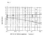
- Fig. 1 shows an effect of the rate of fine particle generation and the selection ratio on the accuracy of analysis.
- the vertical axis is the selection ratio, and the horizontal axis is the rate of fine particle generation.
- the figure represents the relative deviation of element analysis for a standard steel specimen in terms of the elements contained in a range of from 0.01 to 1.0%.
- the symbol of open circle, ( ⁇ ), indicates the relative deviation of 5% or less, and the symbol of open triangle, ( ⁇ ), indicates the relative deviation of above 5%.
- a conventional analytical method gave the relative deviation on S and P in steel at 5% or more.
- the open circles distribute between the boundary line A and the boundary line B, and the distance between these lines A and B broadens with the increase of rate of fine particle generation.
- the selection ratio has to be in a range from 0.8 to 1.25 for conducting the analysis of relative deviation within 5%, but the selection ratio ranging from 0.4 to 1.75 is acceptable at the rate of fine particle generation of 10 ⁇ g/sec.
- the boundary lines A and B are expressed by equations (1) and (2), respectively. S ⁇ 0.25 log 10 V + 1.5, S ⁇ -0.2 log 10 V + 0.6,
- the rate of fine particle generation is specified as 0.1 ⁇ g/sec or more. If the rate of fine particle generation exceeds 100 ⁇ g/sec, a degraded accuracy of detection may be induced caused from an enhanced contamination of excitation source of the detector or from an unstable excitation flame of plasma. Therefore, the upper limit of the rate of fine particle generation is specified as 100 ⁇ g/sec.
- Fig. 1 The result shown in Fig. 1 is applicable also for metals, minerals, ceramics, and other materials, as well as the steel specimen. Furthermore, a melted specimen shows the same trends as in the solid specimen. However, some elements included in these specimens, which elements showed the relative standard deviation within 5%, stayed always near to 5%, and some gave very low value of relative standard deviation. Investigation revealed that the elements giving a large relative deviation were the elements being contained in the metallic material and having a strong tendency to segregation (hereinafter referred to simply as "the segregation elements") or the elements of slight content, and that the elements which uniformly distributed were those of uniform solid solution.
- the segregation elements the elements giving a large relative deviation were the elements being contained in the metallic material and having a strong tendency to segregation (hereinafter referred to simply as "the segregation elements") or the elements of slight content, and that the elements which uniformly distributed were those of uniform solid solution.
- the segregation elements show a strong effect of segregation.
- the effect is, however, buffered by broadening the surface area for generation.
- the means to broaden the generation area include the widening of beam diameter of laser rays and the sweeping action of the laser beam.
- a widened laser beam decreases the energy density per irradiated area, so the method has a limitation. Therefore, the method of beam sweep for moving the focusing point is superior.
- the irradiation area per sec. becomes 10 times that obtained by a stationary focusing point.
- a moving focusing point gives another effect. Repeated irradiation of beam while fixing the focusing point forms a hole having the diameter of beam width on the surface of specimen, and the gathered samples come from the bottom of the hole. Consequently, the distance between the focusing lens and the irradiation plane changes with time, and the sample generation plane becomes out of focus, then the emitted substance becomes hard to diffuse and the quantity of generating fine particles decreases.
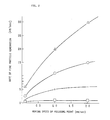
- a moving focusing point prevents the disadvantage and enhances the rate of fine particle generation. Regarding the relation between the rate of fine particle generation and the transfer speed of focusing point, the rate of fine particle generation depends also on the pulse energy density and the oscillation frequency. The relation is given in Fig. 2.
- the vertical axis of Fig. 2 is the rate of fine particle generation, and the horizontal axis is the transfer speed of focusing point.
- the graph shows the relation of these variables at an pulse energy density of 1 GW/cm 2 and an oscillation frequency of 10Hz (open square symbol, ⁇ ), 100Hz (cross symbol, + ), 1KHz (open circle symbol, ⁇ ), and 10KHz (open triangle symbol, ⁇ ).
- the effect of the transfer speed of focusing point appears strongly with the increase of oscillation frequency.
- the rate of fine particle generation saturates in a region of small transfer speed of focusing point when the oscillation frequency is low.
- the rate of fine particle generation is preferably at 0.1 ⁇ g/sec or more, and preferably the pulse energy density is 0.01GW/cm 2 or more, the oscillation frequency of 100Hz or more, and the transfer speed of focusing point of 0.1mm/sec or more. In that preferred case, the rate of fine particle generation becomes 1 ⁇ g/sec or more.
- the value is considered necessary to eliminate the effect of segregation, though the value is considerably larger than 1 ⁇ g/sec which is a required level for the case of 5% or less of the relative standard deviation of segregation elements.
- the saturation point of the rate of fine particle generation becomes high.
- Further preferable condition is prepared at the oscillation frequency of 500Hz or more and the transfer speed of focusing point of 1mm/sec or more to obtain the fine particles stably at a rate of 10 ⁇ g/sec or more.
- the condition allows to determine a slight amount of segregation element at a content of 0.01% or less with a high accuracy.
- Increase of pulse energy density increases the rate of fine particle generation to an adequate range. Over the optimum range, however, a different phenomenon appears and no energy is consumed to generate fine particles any more.
- the approximate limit of the optimum range is 50GW/cm 2 . Beyond the range, the atmospheric gas becomes plasma owing to the electro-magnetic or thermal action of the laser rays, which plasma consumes the energy to induce a drastic reduction of the rate of fine particle generation. If the pulse energy density is below 0.01GW/cm 2 , the rate of fine particle generation decreases and the selective vaporization is enhanced.
- the selective vaporization is affected most significantly by the pulse width.
- the selection ratio decreases.
- a solid specimen containing both Mn having a low boiling point and No having a high boiling point was irradiated by laser rays having a pulse energy density of 1 x 10 7 W/cm 2 at a frequency of 100Hz while varying the half width of pulse to determine the change of selection ratio.
- the result is given in Fig. 3.
- the vertical axis is the selection ratio
- the horizontal axis is the half width of pulse. Longer half width of pulse makes the selection ratio move away from unity.
- a half width of pulse at 0.5 ⁇ sec or less keeps the selection ratio in a range of from 0.6 to 1.6. Longer half width of pulse increases the zone receiving the thermal influence on the solid specimen, and the fraction of fine particle generation through vaporization presumably increases.
- a shortened half width of pulse improves the selection ratio. Nevertheless, the shortening of half width of pulse has a limitation.
- Fig. 4 gives an example of observed efficiency of rate of fine particle generation per pulse.
- the vertical axis is the generation efficiency defined as the amount of fine particle generated per pulse divided by the applied energy (megawatt).
- the horizontal axis is the half width of pulse.
- the half width of pulse becomes below 0.05 ⁇ sec, the efficiency suddenly decreases.
- the wave height of the pulse is required to increase to compensate the shortened half width, which results in a sharp pulse pattern.
- a sharp pulse tends to induce the plasma-forming phenomenon in atmosphere described before. Accordingly, an adequate value of the half width of pulse is 0.05 ⁇ sec or more.
- a preferred mode to secure the amount of fine particle generated is the irradiation of laser rays having a half width of pulse ranging from 0.05 to 0.5 ⁇ sec under the conditions of the energy density ranging from 0.01 to 50GW/cm 2 , and the oscillation frequency of 100Hz or more onto the solid specimen, while transferring the focusing point at a rate of 0.1mm/sec or more.
- This mode allows the analysis of segregation elements within an accuracy of relative standard deviation of 2%. In that case, elements which do not induce segregation are naturally analyzed with a higher accuracy.
- the transfer speed of the focusing point is easily increased by a transfer method which is described later. In particular, the transfer speed of 1mm/sec or more is most preferable for a slight amount of said elements.
- the movement of the focusing point may be done by transferring the solid specimen, and may be done by sweeping the beam.
- the former transfer method may be applied.
- the latter transfer method is superior because the method easily performs a quick movement. The latter method is most preferable for a large specimen and for a heavy specimen.
- An analysis by laser vaporization generally adopts the range of sweeping within several millimeters, which range is narrower than that of laser beam machining. For instance, at a transfer speed of 1mm/sec, when the focusing point travels in zigzag pattern to cover 1mm range with 10 go-and-back cycles at a spacing of 100 ⁇ m, the range of sweep becomes 1mm 2 .
- a practical method of beam sweep is the galvanometer method which uses the rotation of two reflection mirrors and an f ⁇ lens.
- This method has been used in laser beam machining and provides a range of sweeping as wide as several tens of centimeters.
- the method however, has a poor focusing degree and needs a considerably large oscillator to maintain the energy density of 0.01 GW/cm 2 .
- the inventors studied a means to move the focusing point at a high speed without inducing the degradation of pulse energy density, and found that, as far as the moving range of several millimeters square which is necessary for the analysis by laser vaporization, the linkage of the rotating single reflection mirror and the horizontal movement of a single-focus lens achieved the performance.
- Movement of focusing point is actuated either by rotating a reflection mirror or by transferring the focusing lens. Combination of these means increases the speed of movement.
- Fig. 5 illustrates the principle of these means.
- Fig. 5(A) shows a normal use of lens, where the parallel incident light 1 of laser rays is adjusted by a reflection mirror (not shown) and is guided vertically to the center of the focusing lens 2.
- the focusing point P o matches the focus of the focusing lens 2.
- Fig. 5(C) shows the case that the reflection mirror is rotated while the focusing lens 2 does not move. In that case, the incident light enters the focusing lens along the inclined axis, not vertically, and the point of entry shows a drift from the center of the lens. Accordingly, the focusing point P 2 does not match the focus of the focusing lens 2 and moves by the distance corresponding to the inclination of incident light.
- the movement of lens or the rotation of reflection mirror can move the focusing point.
- the distance between the lens and the focusing point is equal to the focusing distance and it remains unchanged.
- the fine particle collecting section of an analytical device by laser vaporization is provided with an irradiation point transfer device having a mechanism which moves the laser ray focusing lens in parallel to the specimen surface and having a mechanism which rotates the reflection mirror, then the movement of focusing point becomes easy under a state of sharp focusing onto the specimen surface.
- the movement of focusing point while maintaining the sharply focused state is an important thing in an analysis by laser vaporization. If the degree of focusing is reduced by the movement of focusing point, the rate of fine particle generation and the selection ratio suffer a bad influence.
- the parallel movement of a focusing lens is easily done in two-axial directions. Solely the parallel movement of the focusing lens may transfer the focusing point, and when the parallel movement is combined with the rotation of the reflection mirror this allows an easy response to the requirement of high speed transfer and of sweep locus. For example, if a mechanism is capable of rotating the reflection mirror around an axis parallel to the irradiation plane and of transferring the focusing lens in axial direction, then the analytical device becomes simple and utilizes efficiently the fine particle generation surface.
- the contamination is another variable to degrade the representative characteristics of the original specimen.
- the former contamination is brought about by sampling also the foreign matter attached to the original specimen for analysis. That type of foreign matter includes dust and dirt, and oxides yielded on the surface, gaseous substances such as CO 2 and hydrocarbons adsorbed on the specimen.
- the fine particle samples are taken from the surface layer of the specimen, they are strongly influenced by the contamination of the surface.
- the surface of an original specimen is often cleaned before the analysis. Nevertheless, it is unavoidably subjected to oxidation to some degree and to contamination by components in the air or suspended particles before being introduced into the fine particle sampling device.
- the contaminants in the air include chemical compounds of hydrocarbons, calcium, sulfur, phosphorus, aluminum, etc. Even when the rate of fine particle generation is at 10 ⁇ g/sec, the generated fine particles are carried by the carrier gas flowing at an approximate rate of 1 l/min, so a component included in the specimen at a content of 0.01wt.% is sent to the detection section at a concentration below 0.1wt.ppm. Therefore, a contaminant existed in air at a very slight amount can not be overlooked, and the specimen is necessary to be cleaned by a highly purified inert atmosphere immediately before generating the fine particle samples.
- Irradiation of laser rays onto a solid specimen induces the generation of fine particles firstly from the top surface layer which contains contaminants. Diffusion of the contaminants including oxides into the original specimen to change the composition of original specimen shall be avoided, though the condition of irradiation during the first stage is not restricted by the conditions to prevent the selective vaporization and removing the surface layer at the original composition.
- the conditions for irradiation at the measurement are the optimum conditions for cleaning. Different from the measuring period, however, there is no need for considering the concentration necessary to obtain a certain level of sensitivity, so the rate of fine particle generation becomes not a significant variable.
- the lower limit of half width of pulse and of energy density become a moderate level, and the upper limit of them is unnecessary to define.
- a preferable condition for practical application is the half width of pulse 0.001 ⁇ sec or more, the pulse energy density of 0.001GW/cm 2 or more, and the oscillation frequency 100Hz or more.
- the transfer speed of focusing point is unnecessary to limit. Nevertheless, since the whole surface area for generating fine particle samples is required to be cleaned, the surface area allocated for the generation of fine particle samples is subjected to sweep-irradiation for a necessary period of cleaning.
- the carrier gas carries away the contaminants which are emitted from the specimen surface as fine particles.
- the measurement is carried out without influence of contaminants. The obtained representative characteristics of the specimen are further improved.
- the contaminants coming from carrier gas include the impurities in the carrier gas itself and those entered during the flow passage of carrier gas.
- carrier gas after purifying to eliminate impurities as far as possible is the same practice used in the purification of solvent in the case of solution specimen.
- a solvent is rarely contaminated on route of flow passage. However, a transporting gas quite often encounters the contamination during its transfer passage.
- the gas supply section also feeds Ar and N 2 for plasma flame, air for atomic absorption flame, acetylene and nitrous oxide for excitation flame of the element detection section.
- the gas for excitation flame is smaller in volume than the carrier gas, it is also purified similar to the carrier gas to prevent contamination in the flow passage.
- a gas purifying device is attached to the gas supply section of an analytical device by laser vaporization to eliminate the impurities in the gas applied, at need.
- the gas purifying system is made by a material having a low reactivity with and low adsorption capacity to impurities in gas and having a high heat durability and being easily cleaned by heating.
- a He gas commercially available at a purity of 99.99999% may often be used without further purification.
- Ar gas of 99.99% purity and N 2 gas of 99.999% purity often undergo further purification before use.
- a metallic getter gas purification device may be used as the gas purification device.
- Commercially available high purity Ar gas has a purity of 99.995%, but that kind of Ar gas includes hydrocarbon gas and contains the impurity carbon at around several ppm. The carbon content corresponds to several times that in a low carbon steel, so the gas needs to be purified further and needs to be protected from recontamination in the succeeding pipeline.
- the impurities in gas is subtracted as blank value, so the concentration of the impurities is not necessarily lower than the concentration level of target component. Nevertheless, a high blank value degrades the accuracy of analysis.
- the gas piping may use metals such as stainless steel and aluminum, or non-porous ceramics such as glass.
- the important precautions for piping include the prevention of invasion of outside gas at a joint section while maintaining easy cleaning configuration of the joint.
- the seal material may use a heat-resistant synthetic rubber containing fluorine. however, sealing materials are unavoidably inferior in their cleanliness compared to metallic or ceramic materials, so the seals should be of minimum surface area.
- Examples of the molten specimen include a molten metal at smelting, and zinc, tin, aluminum, etc. of hot dip coating.
- a solid specimen was irradiated by laser rays to generate fine particles which were then introduced to an excitation flame using a carrier gas to analyze.
- the target specimens for analysis were carbon steel, stainless steel, aluminum alloy, titanium alloy, ceramic material, and copper alloy. Table 1 lists the composition of these specimens.
- a carbon steel was analyzed by emission analysis using an inductively coupled plasma (hereinafter referred to simply as " ICP").
- the device of ICP applied is shown in Fig. 6.
- the laser rays 2 emitted from the laser oscillator 1 are adjusted in their proceeding direction by the reflection mirror 3, focused by the focusing lens 4, then guided to irradiate onto the solid specimen 5.
- the reflection mirror 3 is rotated by the rotary mechanism 6, and the focusing lens 4 is movable by the parallel transfer mechanism 7.
- the solid specimen 5 was placed in the irradiation cell 8, and the carrier gas was introduced to the cell 8.
- the gas supplied from the gas cylinder 10 was purified at the purification device 11, at need, and was sent to the laser irradiation cell 8 or the high frequency induction plasma torch 14 via the piping system 12.
- a Zr getter purification device was used as the purification device 11.
- the piping system 12 was provided with a mass flow regulator 13 to control the gas flow rate.
- Stainless steel was used for the piping, and glass was used for the laser irradiation cell 8 and the plasma torch 14. The joint of these components was done by the joint illustrated in Fig. 9.
- a metallic pipe 31 had a threaded inside step, and the step received a "Viton" O ring 33 which was made from a heat-resistant synthetic rubber containing fluorine. Then a glass tube 32 was inserted in the 0 ring, and the threaded closure 34 was fitted to the metallic pipe 31. The O ring 33 is pressed by the threaded closure 34 to become an elliptical section, which attached tightly to the inner face of the metallic pipe 31 and the outer face of the glass tube 32 to secure the air tightness.
- the laser oscillator employed an ultrasonic Q switch Nd; YAG laser, Ruby laser, EXIMA laser, and CO 2 laser.
- Transfer of the focusing point was carried out by the combination of the rotation of the reflection mirror and the parallel movement of the focusing lens.
- the rotary axis 21 was linked with the step motor 22, and the rotational angle was set corresponding to the distance from the reflection point to the focusing lens, and the direction of rotation was changed using the frequency ranging from 1 to 100Hz.
- the step motor 22 was used to rotate the rotary press rod 23 having a male thread on it, and the rotational movement of the rotary press rod 23 was changed to the linear movement of the lens table 24 having a female thread on it.
- the speed of the transfer was in a range of from 1 to 100mm per minute.
- the direction of lens movement matched the rotational axis of the reflection mirror, and the moving directions of individual focusing points induced by the rotation of the reflection mirror and by the movement of focusing lens cross each other at right angles.
- the preliminary treatment was carried out by the sweep of laser rays having the beam diameter of 200 ⁇ m within a range of 2mm square under the condition of half width of pulse 100 ⁇ see, energy density 0.005 GW/cm 2 , oscillation frequency 5000Hz.
- Table 2 shows the conditions of laser vaporization and the analytical results.
- Examples of this invention gave the analytical values of relative standard deviation within 5% for all elements analyzed.
- Tests No. 1 through 6 which satisfied the conditions of superior mode including half width of pulse, energy density, oscillation frequency, and transfer speed of focusing point showed particularly good results giving relative standard deviation within 2%, except for extremely low B content (Test No. 2). Also for B, when the transfer speed of focusing point exceeds 1mm/sec, the relative standard deviation was within 2%.
- Tests Nos. 7 through 10 were outside of the specified condition for superior mode in each item of energy density (Test No. 7), half width of pulse (Test No. 8), oscillation frequency (Test No. 9), and transfer speed of focusing point (Test No. 10). Nevertheless, those Test Nos. gave a result remaining in the range specified by equations (1), (2), and (3) The relative standard deviation of these analytical values was within 5% for all of them, though some of them exceeded 2%.
- Test No. 11 of the Comparative Examples did not satisfy the equations (1), (2), and (3), and Tests No. 15 and 16 did not undergo gas purification nor preliminary treatment, and had elements exceeding the relative standard deviation of 5%.
- the Conventional Example did not undergo gas purification nor preliminary treatment as in the case of the Comparative Examples, and gave a large relative standard deviation of C which might be difficult to analyze, and gave a large relative standard deviation of P and S which existed at a slight amount and which were easily affected by contaminants.
- MIP microwave induction plasma
- AA atomic absorption
- the MIP emission spectrometry used an MIP torch instead of the ICP torch which was used in Example 1, and used high purity N 2 gas as the carrier gas and the plasma gas.
- the purchased gas contained carbon monoxide of 1ppm, carbon dioxide of 0.1ppm, and methane of 0.1ppm, so the gas was purified using a Zr getter as in Example 1 in advance.
- the preliminary treatment was applied as in the case of Example 1.
- the AA method used Ar as the carrier gas, and acetylene and air as the gas for excitation flame.
- Fig. 10 illustrates the device employed.
- the reference number 41 indicates the fine particle generation section.
- the carrier gas is supplied to the section 41 from the gas cylinder 42.
- the fine particles generated by laser irradiation are sent to the burner 43.
- the reference numbers 44 and 45 indicate air cylinder and acetylene cylinder, respectively, to supply gases for the excitation flame to the burner 43.
- the excitation flame is irradiated by the light containing the target wavelength from the cathode lamp 47.
- the spectrometer 48 receives the light to analyze spectra, and the detector 49 detects the degree of absorption of the target wavelength.
- the detected signals are sent to the data processing device 17 where the analytical values are calculated. Two channels of measurement system are adopted to conduct an internal standard correction.
- Both the gas for carrier gas and the gas for the excitation flame used a commercial high purity gas without further purification. Since the target components were considered as not being much affected by contaminants, the surface of the original specimen was only machine-polished in air, and no preliminary treatment was applied.
- This invention solves the problems on the quantity of fine particles generated from a solid specimen and on the representative characteristics of specimen by adjusting the conditions of laser ray irradiation and by adopting countermeasures to contamination of the specimen.
- the invention allows an analysis of solid specimens to be achieved promptly at a high accuracy. Accordingly, this invention provides a significant effect contributing to the improvement of quality of material produced, the elimination of waste of material, and the improvement of production efficiency.
- Test Sample Composition (wt.%) Carbon Steel C Si Mn P S B 0.25 0.20 0.65 0.01 0.01 0.001 Stainless Steel C Ni Cr Mo - - 0.05 12.1 16.1 2.5 - - Aluminum Alloy Al V Fe Cu S - 6.2 3.9 0.2 0.63 0.01 - Test Sample Composition (wt.%) Titanium Alloy Fe Mg Si Cu S 0.10 5.5 0.82 0.63 0.01 Copper Alloy Be Cd Fe - - 1.89 0.03 0.05 - - Silicon Nitride Al Fe - - - 0.18 0.15 - - - Test No.
Landscapes
- Health & Medical Sciences (AREA)
- Physics & Mathematics (AREA)
- Analytical Chemistry (AREA)
- Biochemistry (AREA)
- Optics & Photonics (AREA)
- Nuclear Medicine, Radiotherapy & Molecular Imaging (AREA)
- Life Sciences & Earth Sciences (AREA)
- Chemical & Material Sciences (AREA)
- Engineering & Computer Science (AREA)
- Plasma & Fusion (AREA)
- General Health & Medical Sciences (AREA)
- General Physics & Mathematics (AREA)
- Immunology (AREA)
- Pathology (AREA)
- Investigating, Analyzing Materials By Fluorescence Or Luminescence (AREA)
- Sampling And Sample Adjustment (AREA)
- Investigating Or Analysing Materials By Optical Means (AREA)
Claims (7)
- Verfahren zum Analysieren einer festen Probe, umfassend die Schritte:Positionieren der festen Probe in einer Zelle;Einführen eines inerten Trägergases in die Zelle, wobei das Trägergas einen Kohlenstoffanteil von 1 ppm oder geringer als Verunreinigung besitzt;Durchführen eines Vorreinigungsschritts durch das Bestrahlen einer Probenoberfläche der festen Probenstückes im inerten Trägergas mit einem Laserstrahl, der eine Pulshalbbreite von 0,001 µsec oder mehr besitzt, eine Pulsenergiedichte von 0,001 GW/cm2 oder mehr und eine Frequenz von 100 Hz oder mehr;Erzeugen feiner Partikeln im Trägergas durch das Bestrahlen des Lasers auf die feste Probe; undRegeln der Pulsenergiedichte, Pulshalbbreite und Oszillationsfrequenz des Laserstrahls, so daß die Erzeugungsrate V (µg/sec) feiner Partikel und das Auswahlverhältnis S die folgenden Gleichungen erfüllt, wobei das Auswahlverhältnis das Verhältnis der Konzentration des zu analysierenden Zielelementes innerhalb der feinen Partikel zur Konzentration des zu analysierenden Zielelementes zur Analyse innerhalb der Feststoffprobe ist:Einführen der erzeugten feinen Partikel in einen Detektor; undAnalysieren der Konzentration des Zielelementes innerhalb der feinen Partikel mit Hilfe des Detektors.
- Verfahren gemäß Anspruch 1, wobei der Schritt des Erzeugens feiner Partikel ausgeführt wird durch das Bestrahlen mit einem Laserstrahl mit einer Pulshalbbreite von 0,05 bis 0,5 µsec, einer Pulsenergiedichte von 0,01 bis 50 GW/cm2 und einer Frequenz von 100 Hz oder mehr.
- Verfahren gemäß Anspruch 2, wobei der Laserstrahl ausgesandt wird, während ein Brennpunkt des Laserstrahls mit einer Geschwindigkeit von 0,1 mm/sec oder mehr parallel zur Oberfläche des Probenkörpers bewegt wird.
- Verfahren gemäß Anspruch 3, wobei die Bewegung des Brennpunkts durch das Bewegen einer Fokussierlinse parallel zur Oberfläche des Probenkörpers ausgeführt wird.
- Verfahren gemäß Anspruch 3, wobei das Bewegen des Brennpunkts durch das Drehen eines Reflexionsspiegels ausgeführt wird.
- Verfahren gemäß Anspruch 1, wobei das Trägergas ein Gas ist, das mit Hilfe einer Getter-Gasreinigungseinrichtung gereinigt ist.
- Verfahren gemäß Anspruch 1, wobei das inerte Trägergas durch ein Gasverrohrungssystem in die Zelle eingeführt wird, das zumindest teilweise aus Metall oder Glas hergestellt ist.
Applications Claiming Priority (4)
| Application Number | Priority Date | Filing Date | Title |
|---|---|---|---|
| JP15941693 | 1993-06-29 | ||
| JP5159416A JP2870364B2 (ja) | 1993-06-29 | 1993-06-29 | レーザー気化分析方法及び装置 |
| JP159416/93 | 1993-06-29 | ||
| CN94115712A CN1117584A (zh) | 1993-06-29 | 1994-08-25 | 分析固体样品的方法 |
Publications (2)
| Publication Number | Publication Date |
|---|---|
| EP0632264A1 EP0632264A1 (de) | 1995-01-04 |
| EP0632264B1 true EP0632264B1 (de) | 1999-12-22 |
Family
ID=37076173
Family Applications (1)
| Application Number | Title | Priority Date | Filing Date |
|---|---|---|---|
| EP94109980A Expired - Lifetime EP0632264B1 (de) | 1993-06-29 | 1994-06-28 | Verfahren zur Untersuchung einer festen Probe |
Country Status (5)
| Country | Link |
|---|---|
| US (1) | US5452070A (de) |
| EP (1) | EP0632264B1 (de) |
| JP (1) | JP2870364B2 (de) |
| CN (1) | CN1117584A (de) |
| DE (1) | DE69422227T2 (de) |
Families Citing this family (10)
| Publication number | Priority date | Publication date | Assignee | Title |
|---|---|---|---|---|
| JP3166569B2 (ja) * | 1995-06-12 | 2001-05-14 | 日本鋼管株式会社 | 鋼材表面に生じた異常部の発生原因検出方法 |
| US5844149A (en) * | 1996-09-19 | 1998-12-01 | Nkk Corporation | Method for analyzing solid specimen and apparatus therefor |
| CN103210303A (zh) * | 2010-10-01 | 2013-07-17 | 技术信息有限公司 | 激光诱导击穿光谱分析仪 |
| US11248961B2 (en) * | 2013-03-15 | 2022-02-15 | Mat International Holdings, Llc | Methods and systems for analyzing samples |
| SG10201808165YA (en) | 2013-04-17 | 2018-10-30 | Fluidigm Canada Inc | Sample analysis for mass cytometry |
| CN103234912B (zh) * | 2013-04-17 | 2015-06-03 | 中国工程物理研究院流体物理研究所 | 超音速切向气流下材料激光反射率动态测量装置及方法 |
| DE102013009962B3 (de) | 2013-06-14 | 2014-11-06 | K+S Aktiengesellschaft | LIBS-Messtubus |
| JP7146905B2 (ja) | 2018-04-18 | 2022-10-04 | 株式会社エス・テイ・ジャパン | レーザーアブレーション装置および分析装置 |
| US12202046B2 (en) * | 2019-12-24 | 2025-01-21 | Battelle Energy Alliance, Llc | Laser ablation methods for producing feedstock powder suitable for laser-based additive manufacturing |
| WO2022034029A1 (en) * | 2020-08-11 | 2022-02-17 | Merck Patent Gmbh | Method for the collection of substances comprised in an environment for analytical purposes |
Family Cites Families (1)
| Publication number | Priority date | Publication date | Assignee | Title |
|---|---|---|---|---|
| JPH03118440A (ja) * | 1989-09-29 | 1991-05-21 | Yokogawa Electric Corp | レーザ装置を有する元素分析装置 |
-
1993
- 1993-06-29 JP JP5159416A patent/JP2870364B2/ja not_active Expired - Lifetime
-
1994
- 1994-06-27 US US08/266,239 patent/US5452070A/en not_active Expired - Fee Related
- 1994-06-28 EP EP94109980A patent/EP0632264B1/de not_active Expired - Lifetime
- 1994-06-28 DE DE69422227T patent/DE69422227T2/de not_active Expired - Fee Related
- 1994-08-25 CN CN94115712A patent/CN1117584A/zh active Pending
Also Published As
| Publication number | Publication date |
|---|---|
| CN1117584A (zh) | 1996-02-28 |
| JP2870364B2 (ja) | 1999-03-17 |
| EP0632264A1 (de) | 1995-01-04 |
| JPH0772047A (ja) | 1995-03-17 |
| US5452070A (en) | 1995-09-19 |
| DE69422227D1 (de) | 2000-01-27 |
| DE69422227T2 (de) | 2000-05-31 |
Similar Documents
| Publication | Publication Date | Title |
|---|---|---|
| US5537206A (en) | Method for analyzing steel and apparatus therefor | |
| US5583634A (en) | Process for elementary analysis by optical emission spectrometry on plasma produced by a laser in the presence of argon | |
| Bian et al. | Non-matrix matched calibration of major and minor concentrations of Zn and Cu in brass, aluminium and silicate glass using NIR femtosecond laser ablation inductively coupled plasma mass spectrometry | |
| US5452070A (en) | Method for analyzing solid sample | |
| Quackatz et al. | In situ chemical analysis of duplex stainless steel weld by laser induced breakdown spectroscopy | |
| Leloup et al. | Quantitative analysis for impurities in uranium by laser ablation inductively coupled plasma mass spectrometry: improvements in the experimental setup | |
| Ishibashi | Rapid analysis of steel by inductively coupled plasma-atomic emission spectrometry and-mass spectrometry with laser ablation solid sampling | |
| JP3348634B2 (ja) | レーザ気化分析方法 | |
| Vervisch et al. | Spectroscopic analysis of a TIG arc plasma | |
| US5644401A (en) | Method for direct chemical analysis of molten metal using spectrometer | |
| KR0138619B1 (ko) | 고체시료의 분석방법(method for analyzing solid sample) | |
| Skinner et al. | Axial Viewing and Modified Cup Design for Direct Sample InsertionInductively Coupled Plasma Atomic Emission Spectrometry | |
| JP3039231B2 (ja) | 鋼成分迅速分析方法及び装置 | |
| Kehden et al. | Direct solids atomic emission spectrometric analysis of metal samples by" laser-induced argon spark ablation" coupled to ICP-OES | |
| Taparli et al. | Tungsten inert gas bead-on-plate weld chemical composition analysis by laser-induced breakdown spectroscopy | |
| WO1996042005A1 (fr) | Procede permettant de determiner la cause de defauts presents sur une surface d'acier | |
| JP2921329B2 (ja) | 鋼片迅速分析方法及び装置 | |
| JPH07234211A (ja) | 溶融金属のレーザー発光分光分析用プローブ及び分析 方法 | |
| Pang | In situ spectroscopic measurements of variable polarity plasma arc welding of aluminum 2219 | |
| Henze et al. | Effects of separately laser-induced metal vapor amounts on the stability of a TIG arc | |
| JP3018909B2 (ja) | レーザー気化微粒子試料採取セル | |
| Cremers et al. | Direct solid metal analysis by laser ablation into the inductively coupled plasma | |
| Guillong | Laser Ablation Inductively Coupled Plasma Mass Spectrometry: Laser ablation system developments and investigations on elemental fractionation | |
| JP3149155B2 (ja) | 金属成分の迅速分析方法および装置 | |
| Eagar et al. | Fusion Welding Research. |
Legal Events
| Date | Code | Title | Description |
|---|---|---|---|
| PUAI | Public reference made under article 153(3) epc to a published international application that has entered the european phase |
Free format text: ORIGINAL CODE: 0009012 |
|
| 17P | Request for examination filed |
Effective date: 19940628 |
|
| AK | Designated contracting states |
Kind code of ref document: A1 Designated state(s): DE FR GB |
|
| 17Q | First examination report despatched |
Effective date: 19961126 |
|
| GRAG | Despatch of communication of intention to grant |
Free format text: ORIGINAL CODE: EPIDOS AGRA |
|
| GRAG | Despatch of communication of intention to grant |
Free format text: ORIGINAL CODE: EPIDOS AGRA |
|
| GRAH | Despatch of communication of intention to grant a patent |
Free format text: ORIGINAL CODE: EPIDOS IGRA |
|
| GRAH | Despatch of communication of intention to grant a patent |
Free format text: ORIGINAL CODE: EPIDOS IGRA |
|
| GRAA | (expected) grant |
Free format text: ORIGINAL CODE: 0009210 |
|
| AK | Designated contracting states |
Kind code of ref document: B1 Designated state(s): DE FR GB |
|
| REF | Corresponds to: |
Ref document number: 69422227 Country of ref document: DE Date of ref document: 20000127 |
|
| ET | Fr: translation filed | ||
| PLBE | No opposition filed within time limit |
Free format text: ORIGINAL CODE: 0009261 |
|
| STAA | Information on the status of an ep patent application or granted ep patent |
Free format text: STATUS: NO OPPOSITION FILED WITHIN TIME LIMIT |
|
| 26N | No opposition filed | ||
| REG | Reference to a national code |
Ref country code: GB Ref legal event code: IF02 |
|
| REG | Reference to a national code |
Ref country code: FR Ref legal event code: TP |
|
| REG | Reference to a national code |
Ref country code: GB Ref legal event code: 732E |
|
| PGFP | Annual fee paid to national office [announced via postgrant information from national office to epo] |
Ref country code: FR Payment date: 20060608 Year of fee payment: 13 |
|
| PGFP | Annual fee paid to national office [announced via postgrant information from national office to epo] |
Ref country code: DE Payment date: 20060622 Year of fee payment: 13 |
|
| PGFP | Annual fee paid to national office [announced via postgrant information from national office to epo] |
Ref country code: GB Payment date: 20060628 Year of fee payment: 13 |
|
| GBPC | Gb: european patent ceased through non-payment of renewal fee |
Effective date: 20070628 |
|
| REG | Reference to a national code |
Ref country code: FR Ref legal event code: ST Effective date: 20080229 |
|
| PG25 | Lapsed in a contracting state [announced via postgrant information from national office to epo] |
Ref country code: DE Free format text: LAPSE BECAUSE OF NON-PAYMENT OF DUE FEES Effective date: 20080101 |
|
| PG25 | Lapsed in a contracting state [announced via postgrant information from national office to epo] |
Ref country code: GB Free format text: LAPSE BECAUSE OF NON-PAYMENT OF DUE FEES Effective date: 20070628 |
|
| PG25 | Lapsed in a contracting state [announced via postgrant information from national office to epo] |
Ref country code: FR Free format text: LAPSE BECAUSE OF NON-PAYMENT OF DUE FEES Effective date: 20070702 |