EP0632232B1 - Stove having a pyrolytic self-cleaning provision - Google Patents
Stove having a pyrolytic self-cleaning provision Download PDFInfo
- Publication number
- EP0632232B1 EP0632232B1 EP94108227A EP94108227A EP0632232B1 EP 0632232 B1 EP0632232 B1 EP 0632232B1 EP 94108227 A EP94108227 A EP 94108227A EP 94108227 A EP94108227 A EP 94108227A EP 0632232 B1 EP0632232 B1 EP 0632232B1
- Authority
- EP
- European Patent Office
- Prior art keywords
- oven
- cleaning
- pyrolytic self
- self
- time
- Prior art date
- Legal status (The legal status is an assumption and is not a legal conclusion. Google has not performed a legal analysis and makes no representation as to the accuracy of the status listed.)
- Expired - Lifetime
Links
Images
Classifications
-
- F—MECHANICAL ENGINEERING; LIGHTING; HEATING; WEAPONS; BLASTING
- F24—HEATING; RANGES; VENTILATING
- F24C—DOMESTIC STOVES OR RANGES ; DETAILS OF DOMESTIC STOVES OR RANGES, OF GENERAL APPLICATION
- F24C14/00—Stoves or ranges having self-cleaning provisions, e.g. continuous catalytic cleaning or electrostatic cleaning
- F24C14/02—Stoves or ranges having self-cleaning provisions, e.g. continuous catalytic cleaning or electrostatic cleaning pyrolytic type
Definitions
- the invention relates to a stove with pyrolytic Self-cleaning, the muffle by one in at least one Wall area arranged heating element and optionally with additional air heating can be operated, the muffle ventilated by a forced air fan and with pyrolytic agents Self-cleaning is equipped and in the exhaust air the muffle is a gas sensor connected to an evaluation unit is arranged.
- a stove with pyrolytic Self-cleaning the muffle by one in at least one Wall area arranged heating element and optionally with additional air heating can be operated, the muffle ventilated by a forced air fan and with pyrolytic agents Self-cleaning is equipped and in the exhaust air the muffle is a gas sensor connected to an evaluation unit is arranged.
- the energy consumption in the previously known methods of pyrolytic self-cleaning to eliminate the above Soiling was defined by one on one Time kept high temperature marked from 480 to 500 °.
- the object of the invention is that for the pyrolytic Self-cleaning process required heating energy to a necessary Minimize dimensions without affecting existing ones Herds major changes need to be made.
- FIG. 1 shows this in the course of the curve 2.
- the curve profile according to FIG. 1 according to FIG. 1 is what has already been said removable, i.e. a heating-up time of 40 minutes, a holding time of 80 minutes and the one that starts afterwards Cooling process without heating operation. You want the pyrolysis process improve energetically, i.e.
- the duration of the heating-up time depends on which stove-specific designs and sizes of the cooking space, how far the stove is when the Pyrolysis is already warmed up and how high the Mains voltage during the pyrolysis period. According to Fig. 1 of the curve profile 1 can be seen that at one Starting temperature of 200 ° C after an oven process the pyrolysis heating-up time can be shortened significantly, with the subsequent standard holding time of 80 minutes consequently the process faster and less energy.
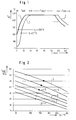
- FIG. 2 a diagram is shown which uses the prevailing mains voltage as a parameter and, depending on the starting temperature, indicates the shortening of the heating-up time that then occurs.
- the reference numerals 3 to 8 mean different parameters of the mains voltage.
- Reference number 3 corresponds to a mains voltage of 215 V
- Reference number 4 corresponds to a mains voltage of 220 V
- Reference number 5 corresponds to a mains voltage of 225 V
- Reference number 6 corresponds to a mains voltage of 230 V
- Reference number 7 corresponds to a mains voltage of 235 V
- Reference number 8 corresponds to a mains voltage of 240 V.
- the evaluation unit is dependent of the real mains voltage for the respective Oven outlet temperature as parameter the heating time corrected.
- the evaluation unit ends the pyrolytic Self-cleaning process after a holding time of approx. 80 minutes, the holding time when the pyrolysis setpoint temperature is reached, which depends on the degree of pollution analysis, begins.
- the holding time is the maximum guideline time understand an underlying time can from the evaluation unit be specified when the degree of pollution analysis this justifies.
- the evaluation unit breaks after the total time by the heating time and the holding time given, the self-cleaning heating process of 120 minutes from.
- the evaluation unit makes sense that do not exceed an upper pyrolysis temperature of 480 ° C otherwise the enamelled parts of the stove interior Get damaged. Therefore the evaluation unit as the maximum pyrolysis setpoint temperature of 480 ° C.
Abstract
Description
Die Erfindung bezieht sich auf einen Herd mit pyrolytischer Selbstreinigung, dessen Muffel durch ein in wenigstens einem Wandbereich angeordnetes Heizelement und gegebenenfalls mit zusätzlicher Umluftheizung betreibbar ist, wobei die Muffel durch ein Umluftgebläse belüftbar und mit Mitteln zur pyrolytischen Selbstreinigung ausgerüstet ist und im Abluftweg der Muffel ein mit einer Auswerteeinheit verbundener Gassensor angeordnet ist. Ein solcher Herd ist im Dokument EP-A-0 529 352 offenbart.The invention relates to a stove with pyrolytic Self-cleaning, the muffle by one in at least one Wall area arranged heating element and optionally with additional air heating can be operated, the muffle ventilated by a forced air fan and with pyrolytic agents Self-cleaning is equipped and in the exhaust air the muffle is a gas sensor connected to an evaluation unit is arranged. Such a range is disclosed in document EP-A-0 529 352.
Beim Braten, Garen und Backen werden die Innenseiten einer Herdmuffel in unterschiedlicher Weise verschmutzt, wobei die Verschmutzung aus Fettresten tierischer und pflanzlicher Art, unterschiedlichen Gargutresten und Kondensationsprodukten von Wrasenbestandteilen besteht.When roasting, cooking and baking, the inside becomes one Muffle soiled in different ways, the Contamination from fat residues from animal and vegetable Type, different food residues and condensation products consists of vapor components.
Der Energieverbrauch bei den bisherig bekannten Methoden der pyrolytischen Selbstreinigung zur Beseitigung der oben genannten Verschmutzungsarten war durch eine auf eine definierte Zeit hoch gehaltene Temperatur von 480 bis 500° gekennzeichnet. The energy consumption in the previously known methods of pyrolytic self-cleaning to eliminate the above Soiling was defined by one on one Time kept high temperature marked from 480 to 500 °.
Aufgabe der Erfindung ist es, die für den pyrolytischen Selbstreinigungsvorgang benötigte Heizenergie auf ein notwendiges Maß zu minimieren, ohne daß dafür an bestehenden Herden wesentliche Änderungen vorgenommen werden müssen.The object of the invention is that for the pyrolytic Self-cleaning process required heating energy to a necessary Minimize dimensions without affecting existing ones Herds major changes need to be made.
Die erfindungsgemäße Lösung dieser Aufgabe ist dem kennzeichnenden Teil der Anspruchs 1 zu entnehmen. Weitere vorteilhafte Ausgestaltungen der Erfindung sind in den Unteransprüchen dargestellt.The inventive solution to this problem can be found in the characterizing part of claim 1. Further advantageous configurations the invention are set out in the subclaims.
Ein Ausführungsbeispiel nach der Erfindung ist im folgenden anhand der Zeichnung näher beschrieben.An embodiment according to the invention is as follows described in more detail with reference to the drawing.
Es zeigt:
- Fig. 1
- ein Temperaturzeitprofil für das pyrolytische Reinigungsverfahren,
- Fig. 2
- ein Temperaturzeitkurvenbild mit der Netzspannung als Parameter.
- Fig. 1
- a temperature-time profile for the pyrolytic cleaning process,
- Fig. 2
- a temperature-time curve with the mains voltage as a parameter.
Gemäß Figur 1 ist erkennbar, daß der pyrolytische Selbstreiniungsvorgang
sich aus drei Phasen zusammensetzt:
Besitzt die Herdmuffel-Raumtemperatur, also ca. 20° C, so
ergibt sich im allgemeinen eine Aufheizzeit von ca. 40 Minuten,
bis die Pyrolysetemperatur von ca. 480° C erreicht
ist. Danach wird eine 80 Minutendauer für den pyrolytischen
Selbstreinigungsvorgang vorgeschrieben. Insgesamt ist der
Vorschrift nach DIN zu entnehmen, daß die Gesamtzeit des
Pyrolysevorganges bis zum Abkühlprozeß 120 Minuten nicht
überschreiten darf. Figur 1 zeigt dies im Kurvenverlauf 2.
Dem Kurvenverlauf nach 2 gemäß Fig. 1 ist das bereits gesagte
entnehmbar, also eine Aufheizdauer von 40 Minuten,
eine Haltezeit von 80 Minuten und der danach einsetzende
Abkühlungsprozeß ohne Heizbetrieb. Will mann den Pyrolysevorgang
energetisch verbessern, d.h. mit möglichst geringer
Energie den pyrolytischen Selbstreinigungsvorgang mit den
vorgeschriebenen Temperaturen durchführen, so ergibt sich,
daß lediglich bei der Verkürzung der Aufheizzeit ein Einsparungseffekt
möglich ist. Die Dauer der Aufheizzeit hängt
davon ab, welche herdspezifischen Konstruktionen und Größen
des Garraumes vorliegen, wie weit der Herd bei Start des
Pyrolysebetriebes bereits erwärmt ist und wie hoch die
Netzspannung im Durchführungszeitraum der Pyrolyse ist. Gemäß
Fig. 1 des Kurvenverlaufs 1 ist erkennbar, daß bei einer
Starttemperatur von 200° C nach einem Backofenvorgang
die Pyrolyseaufheizzeit wesentlich verkürzt werden kann,
mit der anschließenden Normhaltezeit von 80 Minuten verläuft
demzufolge der Prozeß schneller und energieärmer.
Hält man also die Haltezeit des pyrolytischen Selbstreinigungsvorganges
konstant, so kann ein Energiegewinn realisiert
werden, der proportianal zum Zeitgewinn während der
Aufheizzeit entsprechend der Starttemperatur in der Muffel
abläuft. Setzt man eine konstante Netzspannung voraus, beispielsweise
225 V, so ergeben sich bei konstanter Haltezeit
Gesamtersparnis in Minuten von 4 Minuten für 100° C Starttemperatur
bis hin zu 16 Minuten bei Starttemperaturen von
300° C. Für einen mittleren Wert der Backofenstarttemperatur
von 150° C werden beispielsweise 7 Minuten erspart, was
etwa 5,3 % der Gesamtdauer und einem dazu proportional liegenden
Energiegewinn entspricht.Has the range muffle room temperature, i.e. about 20 ° C, so
there is generally a heating-up time of approx. 40 minutes,
until the pyrolysis temperature reaches approx. 480 ° C
is. After that, an 80 minute duration for the pyrolytic
Self-cleaning process prescribed. Overall, the
Regulation according to DIN that the total time of the
Pyrolysis process until the
Es ist außerdem möglich, über verschiedene Sensortechnik und deren Verbindung mit der Auswerteeinheit die notwendige Pyrolysedauer nach Verschutzungsart und Verschmutzungsgrad zu reduzieren. Das würde bedeuten, daß die Haltezeit auf einer der Verschmutzung entsprechenden Temperaturhöhe und Zeitdauer abläuft.It is also possible to use different sensor technology and their connection to the evaluation unit the necessary Pyrolysis time according to type of pollution and degree of pollution to reduce. That would mean that the hold time is on a temperature level corresponding to the pollution and Time expires.
Gemäß Figur 2 ist ein Diagramm dargestellt, das als Parameter
die jeweilig herrschende Netzspannung heranzieht und in
Abhängigkeit von der Starttemperatur die dann auftretende
Verkürzung der Aufheizzeit anbgibt. Dabei bedeuten die Bezugszeichen
3 bis 8 verschiedene Parameter der Netzspannung.
Bezugszeichen 3 entspricht einer Netzspannung von 215 V,
Bezugszeichen 4 entspricht einer Netzspannung von 220 V,
Bezugszeichen 5 entspricht einer Netzspannung von 225 V,
Bezugszeichen 6 entspricht einer Netzspannung von 230 V,
Bezugszeichen 7 entspricht einer Netzspannung von 235 V und
Bezugszeichen 8 entspricht einer Netzspannung von 240 V.According to FIG. 2, a diagram is shown which uses the prevailing mains voltage as a parameter and, depending on the starting temperature, indicates the shortening of the heating-up time that then occurs. The
Reference number 4 corresponds to a mains voltage of 220 V,
Reference number 7 corresponds to a mains voltage of 235 V and
Reference number 8 corresponds to a mains voltage of 240 V.
Unter der Annahme von einer Netzspannung die bei 225 V
liegt ergibt sich also gemäß Kurve 5 für eine Starttemperatur
von 200° C eine Aufheizzeit von 30 Minuten. Dies ist
genau aus dem gemäß Fig. 1 erkennbaren Diagrammverlauf 1
ablesbar. Gemäß Fig. 2 des Kurvenverlaufs 5 ist auch der
Startpunkt des Kurvenverlaufes 2 entnehmbar. So ist ablesbar,
daß bei einer Raumtemperatur von 20 bis 25° C die Aufheizzeit
40 Minuten betägt, entsprechend auch Diagrammverlauf
2 gemäß Fig. 1. Die Zeitgewinne für steigende Netzspannungen
sind zwar nicht erheblich, aber immerhin im Gesamtverlauf
bedeutend. Unter dem Aspekt der Energieeinsparung
erscheint es sinnvoll, daß die Auswerteeinheit dem Benutzer
dann einen pyrolytischen Selbstreinigungsvorgang
vorschlägt, wenn durch einen vorhergegangenen Backofenvorgang
die Starttemperatur für den pyrolytischen Selbstreinigungsvorgang
oberhalb 100° C liegt. Für Temperaturen unterhalb
100° C ist der Gewinn an Energie und Gesamtzeit nicht
so wesentlich. Hinzu kommt, daß die Auswerteeinheit in Abhängigkeit
von der realen Netzspannung für die jeweilige
Backofenausgangstemperatur als Parameter die Aufheizzeit
korrigiert. Die Auswerteeinheit beendet den pyrolytischen
Selbstreinigungsvorgang nach einer Haltezeit von ca. 80 Minuten,
wobei die Haltezeit mit erreichen der Pyrolysesollwerttemperatur,
die von der Verschmutzungsgradanalyse abhängt,
beginnt. Die Haltezeit ist als maximale Richtzeit zu
verstehen, eine darunter liegende Zeit kann von der Auswerteeinheit
vorgegeben werden, wenn die Verschmutzungsgradanalyse
dies rechtfertigt. Wünscht der Benutzer ohne
Empfehlung der Auswerteeinheit einen pyrolytischen Selbstreinigungsvorgang
und startet er ihn ohne einen vorhergegangenen
Backofenvorgang, dann bricht die Auswerteeinheit
nach der Gesamtzeit, die durch die Aufheizzeit und die Haltezeit
gegeben ist, von 120 Minuten den Selbstreinigungsaufheizungsprozeß
ab. Darüber hinaus ist es sinnvoll, daß
eine obere Pyrolysetemperatur von 480° C nicht überschritten
wird, da sonst die emaillierten Bestandteile des Herdinnenraumes
Schaden nehmen. Deshalb läßt die Auswerteeinheit
als maximale Pyrolysesollwerttemperatur 480° C zu.Assuming a mains voltage at 225 V
lies according to
Claims (6)
- Oven with pyrolytic self-cleaning, the oven chamber of which is operable by a heating element, which is arranged in at least one wall region, and optionally with additional circulating air heating, wherein the oven chamber can be loaded with air by an air circulation blower and is equipped with means for pyrolytic self-cleaning and a gas sensor connected with an evaluating unit is arranged in the exhaust air path of the oven chamber, characterised in that the evaluating unit proposes a pyrolytic self-cleaning process to the user when a sensor-monitored, defined degree of contamination is present and when an oven cooking process is concluded and when the oven start temperature lies in a profile, which can be interrogated in the evaluating unit, of oven start temperature and heating-up time, wherein the oven start temperature is the start temperature for the pyrolytic self-cleaning process and the heating-up time is the time during which the oven is brought to a self-cleaning temperature, and wherein the evaluating unit terminates the pyrolytic self-cleaning process after a holding time of up to about 80 minutes for the pyrolytic self-cleaning process.
- Oven with pyrolytic self-cleaning according to claim 1, characterised in that the oven minimum start temperature amounts to 130°C.
- Oven with pyrolytic self-cleaning according to claim 1, characterised in that the evaluating unit corrects the heating-up time in dependence on the actual mains voltage for the oven start temperature as parameter.
- Oven with pyrolytic self-cleaning according to claim 1, characterised in that the holding time begins with attainment of a pyrolysing target value temperature, which depends on the analysis of degree of contamination.
- Oven with pyrolytic self-cleaning according to claim 1, 4, characterised in that the evaluating unit permits 480°C as maximum pyrolysing target value temperature.
- Oven with pyrolytic self-cleaning according to claim 1, characterised in that the evaluating unit interrupts a pyrolytic self-cleaning process, which is commanded by the user, at the latest after 20 minutes.
Applications Claiming Priority (2)
| Application Number | Priority Date | Filing Date | Title |
|---|---|---|---|
| DE4321952 | 1993-07-01 | ||
| DE4321952A DE4321952B4 (en) | 1993-07-01 | 1993-07-01 | Stove with pyrolytic self-cleaning |
Publications (2)
| Publication Number | Publication Date |
|---|---|
| EP0632232A1 EP0632232A1 (en) | 1995-01-04 |
| EP0632232B1 true EP0632232B1 (en) | 1999-01-20 |
Family
ID=6491733
Family Applications (1)
| Application Number | Title | Priority Date | Filing Date |
|---|---|---|---|
| EP94108227A Expired - Lifetime EP0632232B1 (en) | 1993-07-01 | 1994-05-27 | Stove having a pyrolytic self-cleaning provision |
Country Status (4)
| Country | Link |
|---|---|
| EP (1) | EP0632232B1 (en) |
| AT (1) | ATE176041T1 (en) |
| DE (2) | DE4321952B4 (en) |
| ES (1) | ES2130308T3 (en) |
Families Citing this family (3)
| Publication number | Priority date | Publication date | Assignee | Title |
|---|---|---|---|---|
| FR3035482B1 (en) | 2015-04-21 | 2018-09-14 | Groupe Brandt | COOKING APPARATUS EMPLOYING A PYROLYTIC CLEANING CYCLE |
| DE102020121587A1 (en) * | 2020-08-18 | 2022-02-24 | Miele & Cie. Kg | Pyrolytic cleaning of a cooking appliance |
| DE102021202127A1 (en) | 2021-03-04 | 2022-09-08 | BSH Hausgeräte GmbH | Operating a pyrolysis-capable household cooking appliance |
Family Cites Families (5)
| Publication number | Priority date | Publication date | Assignee | Title |
|---|---|---|---|---|
| FR2623884B1 (en) * | 1987-11-27 | 1990-10-26 | Europ Equip Menager | METHOD FOR CONTROLLING THE HEATING TIME FOR A PYROLYSIS CLEANING OF A COOKING OVEN, AND COOKING OVEN IMPLEMENTING THE METHOD |
| DE3924782A1 (en) * | 1989-07-26 | 1991-01-31 | Bosch Siemens Hausgeraete | STOVE WITH PYROLYTIC SELF-CLEANING OF THE MUFFLE |
| DE4017628A1 (en) * | 1990-05-31 | 1991-12-05 | Bosch Siemens Hausgeraete | STOVE WITH PYROLYTIC SELF-CLEANING |
| DE4127389A1 (en) * | 1991-08-19 | 1993-02-25 | Bosch Siemens Hausgeraete | COOKER WITH SENSOR CONTROLLED PYROLYSIS |
| DE4127390A1 (en) * | 1991-08-19 | 1993-02-25 | Bosch Siemens Hausgeraete | AUTOMATED, PYROLYTIC SELF-CLEANING PROCESS |
-
1993
- 1993-07-01 DE DE4321952A patent/DE4321952B4/en not_active Expired - Fee Related
-
1994
- 1994-05-27 AT AT94108227T patent/ATE176041T1/en not_active IP Right Cessation
- 1994-05-27 EP EP94108227A patent/EP0632232B1/en not_active Expired - Lifetime
- 1994-05-27 ES ES94108227T patent/ES2130308T3/en not_active Expired - Lifetime
- 1994-05-27 DE DE59407676T patent/DE59407676D1/en not_active Expired - Fee Related
Also Published As
| Publication number | Publication date |
|---|---|
| EP0632232A1 (en) | 1995-01-04 |
| DE4321952B4 (en) | 2004-05-27 |
| DE4321952A1 (en) | 1995-01-12 |
| ES2130308T3 (en) | 1999-07-01 |
| DE59407676D1 (en) | 1999-03-04 |
| ATE176041T1 (en) | 1999-02-15 |
Similar Documents
| Publication | Publication Date | Title |
|---|---|---|
| EP0529352B1 (en) | Sensor controlled pyrolytic oven | |
| DE1289281C2 (en) | PROCESS AND DEVICE FOR INDEPENDENT CLEANING OF THE INTERIOR SURFACES OF OVENS AND OVENS OF COOKING EQUIPMENT, IN PARTICULAR ELECTRIC STOVES | |
| DE19758860B4 (en) | Method for controlling a pyrolysis cleaning process | |
| DE4223656A1 (en) | Pyrolytic self-cleaning method for oven - Has sensor in cooking space to ascertain degree of contamination and fuzzy logic to control pyrolytic process | |
| EP0632232B1 (en) | Stove having a pyrolytic self-cleaning provision | |
| DE3510680C2 (en) | ||
| DE102014217637A1 (en) | Heating a cooking chamber of a household cooking appliance | |
| EP0528250B1 (en) | Automatable process of pyrolytic self-cleaning | |
| DE3209541A1 (en) | Baking oven | |
| EP2280226A2 (en) | Method for operating a cooking oven and cooking oven | |
| DE20221600U1 (en) | Controlling cooking device, especially domestic cooker, involves selecting cooking procedure with first constant or variable heating power and/or temperature maintenance procedure | |
| DE19839069B4 (en) | Oven with underheat radiator | |
| EP0067806B1 (en) | Gas oven for baking, cooking and grilling food | |
| CH694894A5 (en) | Method for operating a cooking oven and cooking oven. | |
| DE19706277B4 (en) | Oven for fermentation | |
| DE3700136A1 (en) | Process for the pyrolytic cleaning of a baking oven | |
| EP0954973A2 (en) | Proofing chamber with disinfection facility | |
| DE3924782A1 (en) | STOVE WITH PYROLYTIC SELF-CLEANING OF THE MUFFLE | |
| DE2257795C3 (en) | Process for roasting meat or fish and a roasting oven for carrying out the process | |
| DE10046849B4 (en) | Support heating for wood-fired ovens, especially for commercial use | |
| DE1679182A1 (en) | Stove with cleaning of the inner surfaces | |
| DE10336081B4 (en) | Process for baking several baked goods and oven for this | |
| DE19953226A1 (en) | Domestic baking oven with smoke-curing function has control device for heating element for generation of suitable temperature time pattern for smoke-curing and for ventilation valve | |
| DE69917525T2 (en) | Process for cooking food in a cooking oven | |
| DE4114909C2 (en) |
Legal Events
| Date | Code | Title | Description |
|---|---|---|---|
| PUAI | Public reference made under article 153(3) epc to a published international application that has entered the european phase |
Free format text: ORIGINAL CODE: 0009012 |
|
| AK | Designated contracting states |
Kind code of ref document: A1 Designated state(s): AT DE ES FR SE |
|
| 17P | Request for examination filed |
Effective date: 19950612 |
|
| 17Q | First examination report despatched |
Effective date: 19960728 |
|
| GRAG | Despatch of communication of intention to grant |
Free format text: ORIGINAL CODE: EPIDOS AGRA |
|
| GRAG | Despatch of communication of intention to grant |
Free format text: ORIGINAL CODE: EPIDOS AGRA |
|
| RAP1 | Party data changed (applicant data changed or rights of an application transferred) |
Owner name: BSH BOSCH UND SIEMENS HAUSGERAETE GMBH |
|
| GRAG | Despatch of communication of intention to grant |
Free format text: ORIGINAL CODE: EPIDOS AGRA |
|
| GRAH | Despatch of communication of intention to grant a patent |
Free format text: ORIGINAL CODE: EPIDOS IGRA |
|
| GRAH | Despatch of communication of intention to grant a patent |
Free format text: ORIGINAL CODE: EPIDOS IGRA |
|
| GRAA | (expected) grant |
Free format text: ORIGINAL CODE: 0009210 |
|
| AK | Designated contracting states |
Kind code of ref document: B1 Designated state(s): AT DE ES FR SE |
|
| REF | Corresponds to: |
Ref document number: 176041 Country of ref document: AT Date of ref document: 19990215 Kind code of ref document: T |
|
| REF | Corresponds to: |
Ref document number: 59407676 Country of ref document: DE Date of ref document: 19990304 |
|
| ET | Fr: translation filed | ||
| REG | Reference to a national code |
Ref country code: ES Ref legal event code: FG2A Ref document number: 2130308 Country of ref document: ES Kind code of ref document: T3 |
|
| PLBE | No opposition filed within time limit |
Free format text: ORIGINAL CODE: 0009261 |
|
| STAA | Information on the status of an ep patent application or granted ep patent |
Free format text: STATUS: NO OPPOSITION FILED WITHIN TIME LIMIT |
|
| 26N | No opposition filed | ||
| PGFP | Annual fee paid to national office [announced via postgrant information from national office to epo] |
Ref country code: AT Payment date: 20030523 Year of fee payment: 10 Ref country code: FR Payment date: 20030523 Year of fee payment: 10 |
|
| PGFP | Annual fee paid to national office [announced via postgrant information from national office to epo] |
Ref country code: SE Payment date: 20030526 Year of fee payment: 10 Ref country code: ES Payment date: 20030526 Year of fee payment: 10 |
|
| PGFP | Annual fee paid to national office [announced via postgrant information from national office to epo] |
Ref country code: DE Payment date: 20030602 Year of fee payment: 10 |
|
| PG25 | Lapsed in a contracting state [announced via postgrant information from national office to epo] |
Ref country code: AT Free format text: LAPSE BECAUSE OF NON-PAYMENT OF DUE FEES Effective date: 20040527 |
|
| PG25 | Lapsed in a contracting state [announced via postgrant information from national office to epo] |
Ref country code: SE Free format text: LAPSE BECAUSE OF NON-PAYMENT OF DUE FEES Effective date: 20040528 Ref country code: ES Free format text: LAPSE BECAUSE OF NON-PAYMENT OF DUE FEES Effective date: 20040528 |
|
| PG25 | Lapsed in a contracting state [announced via postgrant information from national office to epo] |
Ref country code: DE Free format text: LAPSE BECAUSE OF NON-PAYMENT OF DUE FEES Effective date: 20041201 |
|
| EUG | Se: european patent has lapsed | ||
| PG25 | Lapsed in a contracting state [announced via postgrant information from national office to epo] |
Ref country code: FR Free format text: LAPSE BECAUSE OF NON-PAYMENT OF DUE FEES Effective date: 20050131 |
|
| REG | Reference to a national code |
Ref country code: FR Ref legal event code: ST |
|
| REG | Reference to a national code |
Ref country code: ES Ref legal event code: FD2A Effective date: 20040528 |