EP0631799B1 - Vacuum concentrating plant - Google Patents
Vacuum concentrating plant Download PDFInfo
- Publication number
- EP0631799B1 EP0631799B1 EP94108632A EP94108632A EP0631799B1 EP 0631799 B1 EP0631799 B1 EP 0631799B1 EP 94108632 A EP94108632 A EP 94108632A EP 94108632 A EP94108632 A EP 94108632A EP 0631799 B1 EP0631799 B1 EP 0631799B1
- Authority
- EP
- European Patent Office
- Prior art keywords
- heat
- vacuum
- feed liquid
- vapor
- heating
- Prior art date
- Legal status (The legal status is an assumption and is not a legal conclusion. Google has not performed a legal analysis and makes no representation as to the accuracy of the status listed.)
- Expired - Lifetime
Links
Images

Classifications
-
- C—CHEMISTRY; METALLURGY
- C02—TREATMENT OF WATER, WASTE WATER, SEWAGE, OR SLUDGE
- C02F—TREATMENT OF WATER, WASTE WATER, SEWAGE, OR SLUDGE
- C02F1/00—Treatment of water, waste water, or sewage
- C02F1/02—Treatment of water, waste water, or sewage by heating
- C02F1/04—Treatment of water, waste water, or sewage by heating by distillation or evaporation
- C02F1/046—Treatment of water, waste water, or sewage by heating by distillation or evaporation under vacuum produced by a barometric column
-
- B—PERFORMING OPERATIONS; TRANSPORTING
- B01—PHYSICAL OR CHEMICAL PROCESSES OR APPARATUS IN GENERAL
- B01D—SEPARATION
- B01D3/00—Distillation or related exchange processes in which liquids are contacted with gaseous media, e.g. stripping
- B01D3/007—Energy recuperation; Heat pumps
-
- B—PERFORMING OPERATIONS; TRANSPORTING
- B01—PHYSICAL OR CHEMICAL PROCESSES OR APPARATUS IN GENERAL
- B01D—SEPARATION
- B01D3/00—Distillation or related exchange processes in which liquids are contacted with gaseous media, e.g. stripping
- B01D3/10—Vacuum distillation
-
- B—PERFORMING OPERATIONS; TRANSPORTING
- B01—PHYSICAL OR CHEMICAL PROCESSES OR APPARATUS IN GENERAL
- B01D—SEPARATION
- B01D5/00—Condensation of vapours; Recovering volatile solvents by condensation
- B01D5/0003—Condensation of vapours; Recovering volatile solvents by condensation by using heat-exchange surfaces for indirect contact between gases or vapours and the cooling medium
-
- B—PERFORMING OPERATIONS; TRANSPORTING
- B01—PHYSICAL OR CHEMICAL PROCESSES OR APPARATUS IN GENERAL
- B01D—SEPARATION
- B01D5/00—Condensation of vapours; Recovering volatile solvents by condensation
- B01D5/0033—Other features
- B01D5/0045—Vacuum condensation
-
- B—PERFORMING OPERATIONS; TRANSPORTING
- B01—PHYSICAL OR CHEMICAL PROCESSES OR APPARATUS IN GENERAL
- B01D—SEPARATION
- B01D5/00—Condensation of vapours; Recovering volatile solvents by condensation
- B01D5/0057—Condensation of vapours; Recovering volatile solvents by condensation in combination with other processes
- B01D5/006—Condensation of vapours; Recovering volatile solvents by condensation in combination with other processes with evaporation or distillation
-
- B—PERFORMING OPERATIONS; TRANSPORTING
- B01—PHYSICAL OR CHEMICAL PROCESSES OR APPARATUS IN GENERAL
- B01D—SEPARATION
- B01D5/00—Condensation of vapours; Recovering volatile solvents by condensation
- B01D5/0057—Condensation of vapours; Recovering volatile solvents by condensation in combination with other processes
- B01D5/0075—Condensation of vapours; Recovering volatile solvents by condensation in combination with other processes with heat exchanging
-
- Y—GENERAL TAGGING OF NEW TECHNOLOGICAL DEVELOPMENTS; GENERAL TAGGING OF CROSS-SECTIONAL TECHNOLOGIES SPANNING OVER SEVERAL SECTIONS OF THE IPC; TECHNICAL SUBJECTS COVERED BY FORMER USPC CROSS-REFERENCE ART COLLECTIONS [XRACs] AND DIGESTS
- Y02—TECHNOLOGIES OR APPLICATIONS FOR MITIGATION OR ADAPTATION AGAINST CLIMATE CHANGE
- Y02B—CLIMATE CHANGE MITIGATION TECHNOLOGIES RELATED TO BUILDINGS, e.g. HOUSING, HOUSE APPLIANCES OR RELATED END-USER APPLICATIONS
- Y02B30/00—Energy efficient heating, ventilation or air conditioning [HVAC]
- Y02B30/52—Heat recovery pumps, i.e. heat pump based systems or units able to transfer the thermal energy from one area of the premises or part of the facilities to a different one, improving the overall efficiency
Definitions
- the present invention relates to a vacuum concentrating plant for concentrating a feed liquid at a relatively low temperature by a heating evaporation thereof, which is used to concentrate, for example, a fruit juice, an enzyme, a naturally occurring coloring matter, an yeast extract, a protein solution, an organic acid, a naturally occurring flavoring matter, nucleic acid, medicines or the like, or to concentrate a solution having a low boiling point to recover a solvent therefrom, and particularly, to such a vacuum concentrating plant in which an extremely high heat efficiency can be achieved by combination with a heat pump.
- the EP-A-0006612 discloses a vapor generating and recovering apparatus for vaporizing a liquid and condensating a vapor, the apparatus including a complementary condenser system on the high pressure side of the means to compress a refrigerant.
- the US-A-4638642 discloses a heat pump using water as a refrigerant, the heat pump comprising an evaporator equipped with a feedwater control device and a draining device, a compressor and a condenser with a vacuum generating means.
- the start-up time thereof is shorter, and the set temperature is easy to change. Moreover, the temperature cannot be abnormally risen, leading to a high stability.
- the above prior art plant suffers from many disadvantages. For example, because steam is drawn by using a vacuum pump or an ejector, a large loss of steam is brought out, and because of a large number of components for a circuit system, a great deal of labor is required for maintenance. Further, it is difficult to set the vapor pressure at 0.2 bar (150 Torrs) or more and hence, the temperature of heating steam cannot be brought into 60°C or less.
- the above prior art plant cannot be used for heating and concentrating a feed liquid such as a fruit juice, an enzyme, a naturally occurring coloring matter, an yeast extract, a protein solution, an organic acid, a naturally occurring flavoring matter, nucleic acid, medicines or the like, which are sensitive to a heat, and the above prior art plant exhibits a relatively rough accuracy of adjustment of the set temperature in a range of ⁇ 1 to 3 °C.
- a vacuum concentrating plant which comprises a combination of a heat pump and a vacuum evaporator and is usable at a heating temperature of 60°C or less.
- This plant has been developed to evaporate and concentrate a liquid waste resulting from treatments for photography, as described in Japanese Patent Application Laid-open No.57101/93.
- a coiled condenser of a heat pump is disposed in a concentrator maintained under a reduced pressure by an operation of an ejector, so that the liquid waste is heated under the reduced pressure, and evaporated water is cooled and condensed by a coiled evaporator of the heat pump in a cooling chamber provided around the concentrator and then removed as a drain outside a circuit system.
- the condenser of the heat pump is used as the heating source, but the latent heat of evaporation of freon usually used as a heat transfer medium is relatively low (e.g., the latent heat of evaporation of freon 22 at 35°C is 41 kcal/kg, and the latent heat of evaporation of water is 577 kcal/kg) and hence, the throughput of the feed liquid per unit time can be less increased.
- the known vacuum concentrating plant suffers from following problems: Because it employs a vacuum generating system using an ejector, the degree of vacuum is unstable due to a variation in temperature of circulated cooling water, thereby bringing about a variability in quality, and/or because the condensed water is used, the entrainment contaminates the circulated water and the ejector pump, thereby causing troubles or failures of them.
- a vacuum concentrating plant comprising a heat pump arranged to be switched over between a heating cycle and a refrigerating cycle, a depressurized vapor generator for generating depressurized vapor of a liquid heat-transfer medium under a reduced pressure by an indirect heat exchange with a heating source in the refrigerating cycle of the heat pump, and a vacuum pan evaporator which comprises a steam jacket for indirectly heating a feed liquid by a latent heat by receiving the depressurized vapor generated in the depressurized vapor generator, a feed water concentrating zone for boiling and concentrating the feed liquid at a low temperature under a reduced pressure by a transfer of heat from the steam jacket, and a vapor condenser for cooling and condensing the vapor generated in the feed liquid concentrating zone by an indirect heat exchange with a cooling source in the refrigerating cycle of the heat pump during the start-up of the plant.
- an agitator may be provided for agitating the feed liquid within the vacuum pan evaporator and scraping a concentrate deposited on a wall of the evaporator.
- the feed liquid can be supplied through the feed liquid supply line and via on-off valve into the vacuum evaporator, and a concentrate can be withdrawn from the bottom of the vacuum evaporator via a concentrate withdrawing line having an on-off valve therein.
- a liquid heat-transfer medium temperature adjusting mechanism may be provided for adjusting the temperature of the liquid heat-transfer medium introduced into the depressurized vapor generator to a set value by an indirect heat exchange with the heating source in the heating cycle of the heat pump.
- the liquid heat-transfer medium temperature adjusting mechanism is not mounted as a separate device within the depressurized vapor generator, but may be provided by a condenser which is designed to serve as the heating source in the refrigerating cycle of the heat pump and to be also used as an evaporator serving as a cooling source in the heating cycle by switching-over a pipe line of the heat pump, thereby exhibiting a temperature adjusting function.
- the liquid heat transfer medium is heated by the heating source in the refrigerating cycle of the heat pump within the depressurized vapor generator to generate depressurized vapor.
- This depressurized vapor is introduced into the steam jacket in the vacuum pan evaporator to indirectly heat the feed liquid within the vacuum evaporator.
- the feed liquid within the vacuum evaporator is boiled and concentrated at a low temperature under a reduced pressure.
- the agitator provided within the vacuum evaporator causes the feed liquid to be agitated, while at the same time, causing a concentrate deposited on the wall of the evaporator to be scraped.
- the vapor generated from the feed liquid by the boiling thereof at the low temperature is condensed by the heat exchange with the cooling source in the refrigerating cycle of the heat pump in the vapor condenser provided in an upper portion of the vacuum evaporator, and is then removed in the form of a drain outside the circuit system.
- the depressurized vapor is heated in the vacuum vapor generator by the heating source in the refrigerating cycle of the heat pump having a heat responsiveness, a short start-up time need only be required, and the set temperature can be easily changed. In addition, it is possible to finely adjust the heating temperature and the pressure, and it is also possible to provide a stable operation, because of a less variability in set temperature and pressure.
- the feed liquid is heated by the latent heat of the depressurized vapor, the heat flow amount is far high, as compared with the prior art in which the feed liquid is directly heated by means of the condenser of the heat pump provided within the evaporator, and therefore, the feed liquid can be heated efficiently.
- the former is 41 kcal/kg
- the latter is 577 kcal/kg which is ten times more than the former and therefore, in respect of the heating efficiency per unit flow rate
- the system using the depressurized water vapor is 7 to 10 times more excellent, in actual values, than the prior art system.
- the feed liquid in the vacuum evaporator is boiled and concentrated at the low temperature, it is possible to concentrate the feed liquid at any set temperature in a range of 10 to 110°C by adjusting the degree of vacuum in the vacuum evaporator.
- the agitator for agitating the feed liquid in the vacuum evaporator and scraping the concentrate deposited on the wall of the evaporator is provided as described above, it is possible to enhance the speed of heat exchange of the feed water and to prevent the concentrate from being deposited and scorched onto the wall of the evaporator.
- the vapor condenser added to the vacuum concentrator is cooled by the cooling source in the refrigerating cycle of the heat pump having a good heat responsiveness, it is possible to finely adjust the cooling temperature. Because of the less variability in set temperature, it is possible to provide a stable operation. Moreover, the set temperature can be easily changed.
- the depressurized vapor for heating the feed liquid is used in the closed circuit system, there is no need for supplementing water during operation.
- any other cooling water or the like for the condenser is not used at all and hence, the amount of water consumed is extremely small. Any energy other than an electric power for the operation of the plant is not used at all and hence, the use and management of the system are extremely easy.
- the heat exchange zone for heating the feed water is located in a vapor atmosphere within the vacuum vapor generator, it is less corroded, leading to a reduced cost of maintenance.
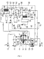
- a vacuum concentrating plant according to the present invention comprises a vacuum pan evaporator 1, a depressurized vapor generator 20 and a heat pump 30.
- the vacuum pan evaporator 1 is comprised of a closed can which includes a feed liquid concentrating zone 2 at a lower portion thereof and a vapor condenser 3 at an upper portion thereof.
- a steam jacket 4 is provided around the lower portion of the vacuum evaporator 1.
- the steam jacket 4 is adapted to heat the vacuum evaporator 1 indirectly and externally by a latent heat by introducing a depressurized vapor generated in the depressurized vapor generator 20 through a depressurized vapor feed pip 15 into the steam jacket 4.
- the depressurized vapor in the steam jacket 4 condensed by heating the vacuum evaporator 1 is passed in the form of a drain through a drain pipe 16 back to the depressurized vapor generator 20.
- An agitator 8 is rotated by the operation of a motor 7 for agitating the feed liquid in the vacuum concentrating zone 2 to provide a uniform heating thereof and to scrape a concentrate deposited onto an evaporator wall.
- a feed liquid supply tank 5 is provided to supply the feed liquid through a feed-liquid supply line 13 having an on-off valve into the vacuum evaporator 1.
- a receiving tank 6 receives a liquid concentrate withdrawn from a bottom of the vacuum evaporator 1 through a liquid concentrate withdrawing pipe 14.
- a drain tank 11 receives a condensate resulting from condensation in a vapor condenser 3 and fed through a line 17.
- a vacuum pump 12 is used to evacuate the vacuum evaporator 1 through lines 17 and 18.
- the depressurized vapor generator 20 is comprised of a closed can having a depressurized vapor generating zone 21 therein.
- the depressurized vapor generator 20 includes a water feed pipe 23 provided at a lower portion thereof for supplying water as a liquid heat transfer medium, and a depressurized vapor feed pipe 15 provided at an upper portion thereof for supplying a depressurized vapor generated in the depressurized vapor generating zone 21 into the steam jacket 4 of the vacuum evaporator 1.
- a pressure adjusting vacuum pump 25 is in communication with the depressurized vapor generator 20 through a line 24.
- a pressure gate valve 26 is provided in the middle of the line 24 and adapted to be automatically closed, when the pressure in the depressurized vapor generator 20 becomes equal to a preset value.
- a heat pump 30 provides a refrigerating cycle during a concentrating operation thereof in a closed circuit comprising a compressor 31, an oil separator 32, a discharge gas solenoid valve 42, a heat exchange coil 33, a liquid solenoid valve 50, a subsidiary condenser 34, a receiver tank 35, a filter drier 36, a liquid solenoid valve 48, an expansion valve 46, a heat exchanger 38 for the vapor condenser, a subsidiary evaporator 39, an accumulator 40, a filter 41 and the compressor 31.
- a blower 51 is provided for blowing air to the subsidiary condenser 34 and is controlable in an on-off manner by the pressure (or temperature) within a circuit system to maintain the pressure in a discharge area constant.
- Further provided components include a blower 52 for the subsidiary evaporator 39, a discharge gas solenoid valve 43 provided in a bypass line 57, a solenoid valve 44 provided in a bypass line 55, an intake gas solenoid valve 45 provided in a bypass line 56, an expansion valve 47 and a liquid solenoid valve 49 provided in a bypass line 58, a pressure gauge 37 at the discharge area, a pressure switch 53, a pressure gauge 54 at an intake area, and a bypass line 59.
- Freon 22 is used as a refrigerant.
- the refrigerant circuit of the heat pump 30 is operated in a heating cycle.
- the discharge gas solenoid valve 43, the intake gas solenoid valve 45, the liquid solenoid valve 49 and the blower 51 are turned ON to provide a closed circuit comprising the compressor 31, the oil separator 32, The discharge gas solenoid valve 43, the subsidiary condenser 34, the receiver tank 35, the filter drier 36, the liquid solenoid valve 49, the expansion valve 47, the heat exchange coil 33, the intake gas solenoid valve, the subsidiary condenser 39 (commonly used as the subsidiary evaporator 39 in a refrigerating circuit), the accumulator 40, the filter 41 and the compressor 31.
- the discharge gas solenoid valve 43, the intake gas solenoid valve 45 and the liquid solenoid valve 49 are turned ON.
- the blower 52 for the subsidiary condenser 39 is controlled in an on-off manner, thereby cooling the heat exchange coil 33 within the depressurized vapor generator 20 to lower the temperature of water in the depressurized vapor generating zone 21, and the pressure in a heat exchange zone 22 is adjusted by the pressure adjusting vacuum pump 25 to provide a temperature required for the concentration.
- the refrigerant circuit of the heat pump 30 is switched into the refrigerating cycle.
- the discharge gas solenoid valve 42 and the liquid solenoid valves 48 and 50 are turned ON, and the blower 52 for the subsidiary condenser 39 and the intake gas solenoid valve 44 are operated and controlled in the on-off manner at the pressure and temperature within the system, thereby heating the heat exchange coil within the depressurized vapor generator 20 to heat and boil the water in the depressurized vapor generating zone at a low temperature, thus generating a depressurized vapor.
- the degree of vacuum within the vacuum pan evaporator 1 is set at a predetermined value by means of the vacuum pump 12 and then, a feed liquid is supplied from the feed liquid supply tank 5 through the feed liquid supply line 13 into the vacuum evaporator 1.
- the depressurized vapor supplied from the depressurized vapor generator 20 through the depressurized vapor supply pipe 15 is introduced into the steam jacket 4 to indirectly heat the feed liquid within the vacuum evaporator 1 by a latent heat.
- the feed liquid within the feed liquid concentrating zone 2 is boiled at a low temperature depending upon the degree of vacuum within the vacuum evaporator 1, so that it is concentrated by evaporation of water.
- the generated vapor is cooled indirectly in the vapor condenser 3 by means of the heat exchanger 38 supplied with the refrigerant in the heat pump 30.
- the cooled and condensed water is passed through the line 17 into the drain tank 11 and stored therein or discharged through the on-off valve to the outside of the circuit system.
- the depressurized vapor used in the steam jacket 4 to indirectly heat the feed water within the vacuum evaporator 1 by the latent heat is condensed and passed in the form of a drain through the drain pipe 16 back to the depressurized vapor generator 20.
- a concentrate as a product is withdrawn into the concentrate receiving tank 6 via the concentrate withdrawing line 14 which is in communication with the bottom of the vacuum evaporator 1.
- the heat pump 30 is switched into and started in the heating cycle to cool water in the depressurized vapor generator 20 to a temperature of approximately 30 °C.
- the vacuum pump 25 is started to adjust the pressure within the depressurized vapor generator 0.0267 to a 0.0533 bar (20 to a 40 Torrs), and the pressure adjusting valve 26 is closed.
- the heat pump 30 is switched into the refrigerating cycle to heat the water in the depressurized vapor generating zone 21 by means of the heat exchange coil 33. This heating generates depressurized vapor having a temperature of about 45 °C.
- the pressure within the vacuum evaporator 1 is set at 0.0133 bar (10 Torrs) by the operation of the vacuum pump 12.
- the feed liquid is supplied from the feed liquid supply tank 5 into the vacuum evaporator 1.
- the depressurized vapor is fed into the steam jacket 4, and the concentrating operation is started.
- Feed liquid to be processed Naturally occurring coloring matter
- Composition of feed liquid containing 98.5 % by weight of water
- Throughput of feed liquid 9.8 kg/hr.
- Output of product 0.29 kg/hr.
- Composition of product containing 50 % by weight of water
- Amount of water evaporated 9.51 kg/hr.
- Color tone of product slightly inferior Result of analysis: a change in quality of material was observed
- the heating temperature is constant, and the throughput per unit time is larger, i.e., the processing time is shorter. Therefore, when a material sensitive to a heat is to be concentrated, the quality of the material is less changed due to the heat, and the quality of the resulting product is remarkably superior, as compared with that produced by the prior art plant.
Applications Claiming Priority (2)
| Application Number | Priority Date | Filing Date | Title |
|---|---|---|---|
| JP182142/93 | 1993-06-29 | ||
| JP5182142A JP2844296B2 (ja) | 1993-06-29 | 1993-06-29 | 真空濃縮装置 |
Publications (2)
| Publication Number | Publication Date |
|---|---|
| EP0631799A1 EP0631799A1 (en) | 1995-01-04 |
| EP0631799B1 true EP0631799B1 (en) | 1997-11-26 |
Family
ID=16113091
Family Applications (1)
| Application Number | Title | Priority Date | Filing Date |
|---|---|---|---|
| EP94108632A Expired - Lifetime EP0631799B1 (en) | 1993-06-29 | 1994-06-06 | Vacuum concentrating plant |
Country Status (6)
| Country | Link |
|---|---|
| US (1) | US5417084A (ja) |
| EP (1) | EP0631799B1 (ja) |
| JP (1) | JP2844296B2 (ja) |
| KR (1) | KR970009639B1 (ja) |
| DE (1) | DE69406987T2 (ja) |
| TW (1) | TW247277B (ja) |
Families Citing this family (16)
| Publication number | Priority date | Publication date | Assignee | Title |
|---|---|---|---|---|
| KR100374845B1 (ko) * | 2000-09-29 | 2003-03-04 | 민중기 | 두부의 제조방법 |
| FR2840542B1 (fr) * | 2002-06-07 | 2005-03-18 | Andre Champeau | Distillateur d'effluents liquides, aqueux ou organiques a regeneration |
| AU2003244295A1 (en) * | 2002-06-19 | 2004-01-06 | Asahi Glass Company, Limited | Process for the recovery of fluorine-containing emulsifiers |
| NZ520365A (en) * | 2002-07-24 | 2004-12-24 | Distech Ltd | Vacuum sealing arrangement for a liquid concentrator |
| EP1526859B1 (en) * | 2002-08-07 | 2012-10-24 | Laboratoire Medidom S.A. | Process for preparing a sterile high molecular weight hyaluronic acid formulation |
| SE526792C2 (sv) * | 2004-03-03 | 2005-11-08 | Tetra Laval Holdings & Finance | Anordning för evaporativ kylning av en vätskeformig produkt |
| DE102008013933A1 (de) * | 2008-03-12 | 2009-11-05 | Areva Np Gmbh | Verfahren und Vorrichtung zum Abtrennen eines Neutronenabsorbers von einem Kühlmittel eines Kühlkreislaufes |
| JP5806489B2 (ja) * | 2011-03-30 | 2015-11-10 | 株式会社大川原製作所 | 遠心式薄膜真空蒸発装置が具えられた濃縮装置並びにその運転方法 |
| CN102651455B (zh) | 2012-02-28 | 2015-11-25 | 京东方科技集团股份有限公司 | Oled器件、amoled器件及其制造方法 |
| CN103721428A (zh) * | 2013-12-11 | 2014-04-16 | 胡瀛 | 一种蒸发器 |
| CN103691137B (zh) * | 2013-12-26 | 2015-05-06 | 龙源海洋生物股份有限公司 | 一种鱼压榨液浓缩设备 |
| CN107062695A (zh) * | 2017-04-18 | 2017-08-18 | 广东美的制冷设备有限公司 | 空调系统 |
| CN108815870B (zh) * | 2018-08-06 | 2023-09-05 | 合众环境(北京)股份有限公司 | 一种mvr蒸发系统 |
| CN113005004B (zh) * | 2020-06-06 | 2022-12-13 | 广州思拓生物技术有限公司 | 一种涂覆面积大的生物酶浓缩装置 |
| CN112772805A (zh) * | 2021-01-30 | 2021-05-11 | 乳山中诚果汁饮料有限公司 | 一种浓缩果汁的制备设备及其制备工艺 |
| CN114522433B (zh) * | 2022-03-14 | 2023-11-10 | 扬州福尔喜果蔬汁机械有限公司 | 一种闭式热循环热泵超低温蒸发浓缩系统的工作方法 |
Family Cites Families (16)
| Publication number | Priority date | Publication date | Assignee | Title |
|---|---|---|---|---|
| NL111824C (ja) * | 1955-06-28 | |||
| US3376652A (en) * | 1966-06-17 | 1968-04-09 | Luis A. Hernandez Jr. | Low temperature freeze drying process and apparatus therefor |
| US3494139A (en) * | 1967-01-23 | 1970-02-10 | Virtis Co Inc | Freeze concentrator |
| US3486985A (en) * | 1969-03-18 | 1969-12-30 | Carrier Corp | Flash distillation apparatus with refrigerant heat exchange circuits |
| US3574950A (en) * | 1969-06-12 | 1971-04-13 | Jospeh L Dantoni | Lyophilizing apparatus |
| US4016657A (en) * | 1971-07-14 | 1977-04-12 | Passey Now By Change Of Name C | Heat pump freeze drying system |
| US3820349A (en) * | 1973-05-01 | 1974-06-28 | Carrier Corp | Sludge separation system |
| DE2966548D1 (en) * | 1978-06-28 | 1984-02-23 | James W Mccord | Vapor generating and recovering apparatus |
| US4973387A (en) * | 1982-12-28 | 1990-11-27 | Allied-Signal Inc. | Apparatus and method for reducing solvent losses |
| JPS60147067A (ja) * | 1984-01-10 | 1985-08-02 | 協和醗酵工業株式会社 | ヒ−トポンプ |
| US5143585A (en) * | 1988-09-20 | 1992-09-01 | Konica Corporation | Method of removing organic solvents |
| JPH0641601Y2 (ja) * | 1988-10-12 | 1994-11-02 | 昭和鉄工株式会社 | 減圧濃縮機 |
| US4952290A (en) * | 1989-03-16 | 1990-08-28 | Amp Incorporated | Waste water treatment and recovery system |
| NL8902621A (nl) * | 1989-10-23 | 1991-05-16 | Grasso Koninkl Maschf | Werkwijze voor het vervaardigen van geconcentreerde voedingsvloeistoffen. |
| JP3179118B2 (ja) * | 1991-01-31 | 2001-06-25 | 東京電力株式会社 | 水溶液の蒸発濃縮装置 |
| JP2941450B2 (ja) * | 1991-01-31 | 1999-08-25 | コニカ株式会社 | 水溶液の蒸発濃縮装置 |
-
1993
- 1993-06-29 JP JP5182142A patent/JP2844296B2/ja not_active Expired - Lifetime
-
1994
- 1994-06-06 DE DE69406987T patent/DE69406987T2/de not_active Expired - Fee Related
- 1994-06-06 EP EP94108632A patent/EP0631799B1/en not_active Expired - Lifetime
- 1994-06-14 US US08/261,143 patent/US5417084A/en not_active Expired - Fee Related
- 1994-06-23 KR KR1019940014502A patent/KR970009639B1/ko not_active IP Right Cessation
- 1994-06-25 TW TW083105789A patent/TW247277B/zh active
Also Published As
| Publication number | Publication date |
|---|---|
| JPH078704A (ja) | 1995-01-13 |
| TW247277B (ja) | 1995-05-11 |
| KR970009639B1 (ko) | 1997-06-17 |
| EP0631799A1 (en) | 1995-01-04 |
| DE69406987T2 (de) | 1998-04-02 |
| JP2844296B2 (ja) | 1999-01-06 |
| DE69406987D1 (de) | 1998-01-08 |
| US5417084A (en) | 1995-05-23 |
| KR950000571A (ko) | 1995-01-03 |
Similar Documents
| Publication | Publication Date | Title |
|---|---|---|
| EP0631799B1 (en) | Vacuum concentrating plant | |
| JPH07508926A (ja) | 水蒸留装置 | |
| US6010599A (en) | Compact vacuum distillation device | |
| JP2844295B2 (ja) | 真空濃縮装置 | |
| US4424633A (en) | Apparatus for heating and drying articles | |
| KR860001490B1 (ko) | 염수로부터 청수(淸水)를 얻기위한 염수의 증류방법 및 장치 | |
| US2777514A (en) | Method and apparatus for concentrating liquids | |
| US4076576A (en) | Method and apparatus for the evaporation of liquids | |
| GB2035813A (en) | Heat pump type water distilling apparatus | |
| US4719016A (en) | Pervaporization method and apparatus | |
| US2570213A (en) | Milk evaporation process and apparatus | |
| JP2000024403A (ja) | 水溶液の蒸発式濃縮装置 | |
| JP3712036B2 (ja) | 塩水淡水化装置 | |
| JPS59132903A (ja) | 濃縮晶出方法 | |
| CN215841628U (zh) | 蒸汽循环供热盘式蒸发设备 | |
| JPH0587453A (ja) | ヒートポンプ式真空蒸発・乾燥装置 | |
| KR200257841Y1 (ko) | 벌꿀 농축장치 | |
| US4249864A (en) | Centrifugal pump system for water desalinization | |
| JPS5821554B2 (ja) | 蒸溜装置 | |
| JP4112772B2 (ja) | 淡水化装置 | |
| JP2000004790A (ja) | キャンディーの濃縮方法及び装置 | |
| KR200242657Y1 (ko) | 음식물쓰레기 탈리액 증발장치 | |
| JPH067881B2 (ja) | 蒸溜液製造装置 | |
| JPH01256701A (ja) | 吹込蒸気供給システム | |
| JPH10118402A (ja) | 液体濃縮方法 |
Legal Events
| Date | Code | Title | Description |
|---|---|---|---|
| PUAI | Public reference made under article 153(3) epc to a published international application that has entered the european phase |
Free format text: ORIGINAL CODE: 0009012 |
|
| AK | Designated contracting states |
Kind code of ref document: A1 Designated state(s): DE FR GB IT NL |
|
| 17P | Request for examination filed |
Effective date: 19950428 |
|
| GRAG | Despatch of communication of intention to grant |
Free format text: ORIGINAL CODE: EPIDOS AGRA |
|
| GRAG | Despatch of communication of intention to grant |
Free format text: ORIGINAL CODE: EPIDOS AGRA |
|
| D17Q | First examination report despatched (deleted) | ||
| GRAH | Despatch of communication of intention to grant a patent |
Free format text: ORIGINAL CODE: EPIDOS IGRA |
|
| GRAH | Despatch of communication of intention to grant a patent |
Free format text: ORIGINAL CODE: EPIDOS IGRA |
|
| GRAA | (expected) grant |
Free format text: ORIGINAL CODE: 0009210 |
|
| AK | Designated contracting states |
Kind code of ref document: B1 Designated state(s): DE FR GB IT NL |
|
| REF | Corresponds to: |
Ref document number: 69406987 Country of ref document: DE Date of ref document: 19980108 |
|
| ITF | It: translation for a ep patent filed |
Owner name: STUDIO TORTA S.R.L. |
|
| ITPR | It: changes in ownership of a european patent |
Owner name: CESSIONE EPO REG. 20;SAKUMA MASAKI |
|
| ET | Fr: translation filed | ||
| PGFP | Annual fee paid to national office [announced via postgrant information from national office to epo] |
Ref country code: GB Payment date: 19980518 Year of fee payment: 5 |
|
| PGFP | Annual fee paid to national office [announced via postgrant information from national office to epo] |
Ref country code: FR Payment date: 19980617 Year of fee payment: 5 |
|
| PGFP | Annual fee paid to national office [announced via postgrant information from national office to epo] |
Ref country code: NL Payment date: 19980625 Year of fee payment: 5 |
|
| RAP2 | Party data changed (patent owner data changed or rights of a patent transferred) |
Owner name: SAKUMA. MASAKI |
|
| PGFP | Annual fee paid to national office [announced via postgrant information from national office to epo] |
Ref country code: DE Payment date: 19980831 Year of fee payment: 5 |
|
| NLT2 | Nl: modifications (of names), taken from the european patent patent bulletin |
Owner name: SAKUMA. MASAKI |
|
| PLBE | No opposition filed within time limit |
Free format text: ORIGINAL CODE: 0009261 |
|
| STAA | Information on the status of an ep patent application or granted ep patent |
Free format text: STATUS: NO OPPOSITION FILED WITHIN TIME LIMIT |
|
| 26N | No opposition filed | ||
| PG25 | Lapsed in a contracting state [announced via postgrant information from national office to epo] |
Ref country code: GB Free format text: LAPSE BECAUSE OF NON-PAYMENT OF DUE FEES Effective date: 19990606 |
|
| PG25 | Lapsed in a contracting state [announced via postgrant information from national office to epo] |
Ref country code: FR Free format text: THE PATENT HAS BEEN ANNULLED BY A DECISION OF A NATIONAL AUTHORITY Effective date: 19990630 |
|
| PG25 | Lapsed in a contracting state [announced via postgrant information from national office to epo] |
Ref country code: NL Free format text: LAPSE BECAUSE OF NON-PAYMENT OF DUE FEES Effective date: 20000101 |
|
| GBPC | Gb: european patent ceased through non-payment of renewal fee |
Effective date: 19990606 |
|
| NLV4 | Nl: lapsed or anulled due to non-payment of the annual fee |
Effective date: 20000101 |
|
| PG25 | Lapsed in a contracting state [announced via postgrant information from national office to epo] |
Ref country code: DE Free format text: LAPSE BECAUSE OF NON-PAYMENT OF DUE FEES Effective date: 20000503 |
|
| REG | Reference to a national code |
Ref country code: FR Ref legal event code: ST |
|
| PG25 | Lapsed in a contracting state [announced via postgrant information from national office to epo] |
Ref country code: IT Free format text: LAPSE BECAUSE OF NON-PAYMENT OF DUE FEES;WARNING: LAPSES OF ITALIAN PATENTS WITH EFFECTIVE DATE BEFORE 2007 MAY HAVE OCCURRED AT ANY TIME BEFORE 2007. THE CORRECT EFFECTIVE DATE MAY BE DIFFERENT FROM THE ONE RECORDED. Effective date: 20050606 |