EP0631207B1 - Prozesseinheit und Bilderzeugungsgerät - Google Patents
Prozesseinheit und Bilderzeugungsgerät Download PDFInfo
- Publication number
- EP0631207B1 EP0631207B1 EP19940401449 EP94401449A EP0631207B1 EP 0631207 B1 EP0631207 B1 EP 0631207B1 EP 19940401449 EP19940401449 EP 19940401449 EP 94401449 A EP94401449 A EP 94401449A EP 0631207 B1 EP0631207 B1 EP 0631207B1
- Authority
- EP
- European Patent Office
- Prior art keywords
- opening
- seal
- sealing
- toner
- tear tape
- Prior art date
- Legal status (The legal status is an assumption and is not a legal conclusion. Google has not performed a legal analysis and makes no representation as to the accuracy of the status listed.)
- Expired - Lifetime
Links
Images


Classifications
-
- G—PHYSICS
- G03—PHOTOGRAPHY; CINEMATOGRAPHY; ANALOGOUS TECHNIQUES USING WAVES OTHER THAN OPTICAL WAVES; ELECTROGRAPHY; HOLOGRAPHY
- G03G—ELECTROGRAPHY; ELECTROPHOTOGRAPHY; MAGNETOGRAPHY
- G03G21/00—Arrangements not provided for by groups G03G13/00 - G03G19/00, e.g. cleaning, elimination of residual charge
- G03G21/16—Mechanical means for facilitating the maintenance of the apparatus, e.g. modular arrangements
- G03G21/18—Mechanical means for facilitating the maintenance of the apparatus, e.g. modular arrangements using a processing cartridge, whereby the process cartridge comprises at least two image processing means in a single unit
- G03G21/1803—Arrangements or disposition of the complete process cartridge or parts thereof
- G03G21/1828—Prevention of damage or soiling, e.g. mechanical abrasion
- G03G21/1832—Shielding members, shutter, e.g. light, heat shielding, prevention of toner scattering
-
- G—PHYSICS
- G03—PHOTOGRAPHY; CINEMATOGRAPHY; ANALOGOUS TECHNIQUES USING WAVES OTHER THAN OPTICAL WAVES; ELECTROGRAPHY; HOLOGRAPHY
- G03G—ELECTROGRAPHY; ELECTROPHOTOGRAPHY; MAGNETOGRAPHY
- G03G15/00—Apparatus for electrographic processes using a charge pattern
- G03G15/06—Apparatus for electrographic processes using a charge pattern for developing
- G03G15/08—Apparatus for electrographic processes using a charge pattern for developing using a solid developer, e.g. powder developer
- G03G15/0822—Arrangements for preparing, mixing, supplying or dispensing developer
- G03G15/0877—Arrangements for metering and dispensing developer from a developer cartridge into the development unit
- G03G15/0881—Sealing of developer cartridges
- G03G15/0882—Sealing of developer cartridges by a peelable sealing film
-
- G—PHYSICS
- G03—PHOTOGRAPHY; CINEMATOGRAPHY; ANALOGOUS TECHNIQUES USING WAVES OTHER THAN OPTICAL WAVES; ELECTROGRAPHY; HOLOGRAPHY
- G03G—ELECTROGRAPHY; ELECTROPHOTOGRAPHY; MAGNETOGRAPHY
- G03G15/00—Apparatus for electrographic processes using a charge pattern
- G03G15/06—Apparatus for electrographic processes using a charge pattern for developing
- G03G15/08—Apparatus for electrographic processes using a charge pattern for developing using a solid developer, e.g. powder developer
- G03G15/0822—Arrangements for preparing, mixing, supplying or dispensing developer
- G03G15/0877—Arrangements for metering and dispensing developer from a developer cartridge into the development unit
- G03G15/0881—Sealing of developer cartridges
- G03G15/0884—Sealing of developer cartridges by a sealing film to be ruptured or cut
-
- G—PHYSICS
- G03—PHOTOGRAPHY; CINEMATOGRAPHY; ANALOGOUS TECHNIQUES USING WAVES OTHER THAN OPTICAL WAVES; ELECTROGRAPHY; HOLOGRAPHY
- G03G—ELECTROGRAPHY; ELECTROPHOTOGRAPHY; MAGNETOGRAPHY
- G03G21/00—Arrangements not provided for by groups G03G13/00 - G03G19/00, e.g. cleaning, elimination of residual charge
- G03G21/16—Mechanical means for facilitating the maintenance of the apparatus, e.g. modular arrangements
- G03G21/1642—Mechanical means for facilitating the maintenance of the apparatus, e.g. modular arrangements for connecting the different parts of the apparatus
- G03G21/1647—Mechanical connection means
-
- G—PHYSICS
- G03—PHOTOGRAPHY; CINEMATOGRAPHY; ANALOGOUS TECHNIQUES USING WAVES OTHER THAN OPTICAL WAVES; ELECTROGRAPHY; HOLOGRAPHY
- G03G—ELECTROGRAPHY; ELECTROPHOTOGRAPHY; MAGNETOGRAPHY
- G03G21/00—Arrangements not provided for by groups G03G13/00 - G03G19/00, e.g. cleaning, elimination of residual charge
- G03G21/16—Mechanical means for facilitating the maintenance of the apparatus, e.g. modular arrangements
- G03G21/1661—Mechanical means for facilitating the maintenance of the apparatus, e.g. modular arrangements means for handling parts of the apparatus in the apparatus
- G03G21/1671—Mechanical means for facilitating the maintenance of the apparatus, e.g. modular arrangements means for handling parts of the apparatus in the apparatus for the photosensitive element
-
- G—PHYSICS
- G03—PHOTOGRAPHY; CINEMATOGRAPHY; ANALOGOUS TECHNIQUES USING WAVES OTHER THAN OPTICAL WAVES; ELECTROGRAPHY; HOLOGRAPHY
- G03G—ELECTROGRAPHY; ELECTROPHOTOGRAPHY; MAGNETOGRAPHY
- G03G2221/00—Processes not provided for by group G03G2215/00, e.g. cleaning or residual charge elimination
- G03G2221/16—Mechanical means for facilitating the maintenance of the apparatus, e.g. modular arrangements and complete machine concepts
- G03G2221/163—Mechanical means for facilitating the maintenance of the apparatus, e.g. modular arrangements and complete machine concepts for the developer unit
- G03G2221/1633—Details concerning the developing process
-
- G—PHYSICS
- G03—PHOTOGRAPHY; CINEMATOGRAPHY; ANALOGOUS TECHNIQUES USING WAVES OTHER THAN OPTICAL WAVES; ELECTROGRAPHY; HOLOGRAPHY
- G03G—ELECTROGRAPHY; ELECTROPHOTOGRAPHY; MAGNETOGRAPHY
- G03G2221/00—Processes not provided for by group G03G2215/00, e.g. cleaning or residual charge elimination
- G03G2221/16—Mechanical means for facilitating the maintenance of the apparatus, e.g. modular arrangements and complete machine concepts
- G03G2221/1648—Mechanical means for facilitating the maintenance of the apparatus, e.g. modular arrangements and complete machine concepts using seals, e.g. to prevent scattering of toner
Definitions
- the present invention relates to an image forming apparatus and a detachable process cartridge therefor.
- the image forming apparatus may be in the form of an electrophotographic copying machine or a printer, using a developer.
- Electrophotographic image forming apparatus are widely used as copying machines or the like.
- a photosensitive drum 1 is uniformly charged and is selectively exposed to form a latent image.
- the latent image is visualized with a developer, and the visualized image is transferred onto a recording material.
- a photosensitive drum and a developing device having a developer container or the like are unified into a cartridge.
- the cartridge is mounted to a main assembly of the apparatus.
- the latent image formed on the photosensitive drum is developed using a developer accommodated in the developer container in the cartridge.
- the opening of the developer container is sealed by a sealing member.
- the operator Prior to the start of the use, the operator removes the sealing member to open the developer container, by which the developer contained in the container is supplied to the developing roller or the like through the opening.
- the opening action is not performed as desired with the result that a desired opening region is not provided.
- the present invention is concerned with improving the operativity in removing the sealing member whilst effectively preventing developer from leaking out.
- a process cartridge detachably mountable to a main assembly of an electrophotographic image forming apparatus comprising: an electrophotographic photosensitive member which can bear a latent image; a first frame having a developer container for containing a developer; a second frame having a developer carrying member for carrying the developer supplied from the developer container to develop the latent image; and a sealing member for sealing an opening for supplying the developer from the developer container to the developer carrying member, wherein the sealing member can be pulled between the first and second frame in a pulling di.rection to open the opening; characterised by: an end seal disposed downstream of said opening with respect to the pulling direction; and a pair of projections provided between the first and second frames at respective lateral sides of the sealing member with respect to the pulling direction and extending through holes in the end seal, for confining the pulling direction of the sealing member.
- Figure 1 is a sectional view of an image forming apparatus according to an embodiment of the present invention.
- Figure 2 is a sectional view of a process cartridge according to an embodiment of the present invention.
- Figure 3 is a sectional view of the image forming apparatus when it is opened.
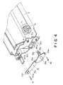
- Figure 4 illustrates a photosensitive drum mounting member
- Figure 5 is a sectional view of a second conductive member of the mounting member.
- Figure 6 shows dimensions of the mounting member.
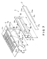
- Figure 7 is a perspective view wherein a toner container, an opening regulating member and a cover member are disassembled.
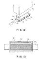
- Figure 8A is a sectional view of a cover seal.
- Figure 8B is a sectional view of a tear tape.
- Figure 9 illustrates a tear tape according to a further embodiment.
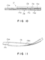
- Figure 10 is a sectional view of a cover member having integral cover seal and a tear tape.
- Figure 11 illustrates a covering member which is curled.
- Figure 12 illustrates fusing of a cover member to an opening regulating member.
- Figure 13 illustrates a ratio of the cover seal and the tear tape.
- Figure 14 illustrates mounting of a developing frame to a toner container with a sealing member.
- Figure 15 illustrates pressure applied to the cover seal by an internal pressure of the toner container.
- Figure 16 illustrates a torn cover seal
- Figure 17 is a sectional view of an example having an end seal.
- Figure 18 illustrates a limiting boss for limiting pulling of the tear tape.
- Figure 19 is a table of experimental results of strength of a tear tape against pulling.
- Figure 20 is a table of experimental results of strength against opening of the process cartridge.
- Figure 21 is a table of experimental results of strength against opening of the process cartridge and a strength of the tear tape against pulling.
- Figure 22 is a table of experimental results about strengths of the toner container and the process cartridge against pressure and falling test.
- Figure 23 is a table of experimental results about tear expansion of the cover seal and stability of tearing, when the tear tape is pulled.
- Figure 24 is a table of experimental results about residual sealant and improper image formation, when the tear tape is pulled out.
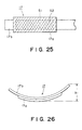
- Figure 25 illustrates a conventional sealing member in which a cover film and a tear tape are entirely heat-sealed.
- Figure 26 illustrates curling of the sealing member.
- Figure 27 illustrates a sealing member in which a cover film and a tear tape are heat-sealed at an overlapped marginal regions.
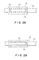
- Figure 28 illustrates a sealing member in which a cover film and a tear tape are heat-sealed at spots in a longitudinal periphery.
- Figure 29 illustrates a sealing member wherein the heat seal is omitted at one of short side around the overlapped portion of the cover film and the tear tape.
- Figure 30 illustrates a sealing member in which the heat sealing is effect only an internal periphery of the overlapped portion between the cover film and the tear tape.
- Figure 31 illustrates a seal pattern according to a first embodiment in which the sealing member is sealed in a mountain pattern on an opening limiting member.
- Figure 32 illustrates a conventional seal pattern in which the sealing member is sealed in the form of a frame on the opening limiting member.
- Figure 33 illustrates a conventional seal pattern in which a sealing member is sealed in the form of a mountain on an opening regulating member, and a seal width is uniform.
- Figure 34 illustrates a toner container having sealing member, to which a developing frame is mounted.
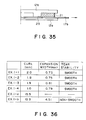
- Figure 35 is a sectional view having an end seal.
- Figure 36 is a table of experimental results as to amount of curling, tearing expansion width and tearing stability in a heat seal pattern of the cover film and the tear tape.
- Figure 37 is a table of seal pattern dimensions for heat seal of the sealing member in experiment 2-1.
- Figure 38 shows results of puncture strength and falling test in experiment 2-1.
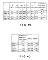
- Figure 39 is a table of seal pattern dimensions for heat seal of the sealing member in experiment 2-2.
- Figure 40 is a table of results of puncture strength and a falling test in experiment 2-2.
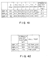
- Figure 41 is a table of seal pattern dimensions for heat seal of the sealing member in experiment 2-3.
- Figure 42 is a table of puncture strength and falling test in experiment 2-3.
- Figure 43 is a table of seal pattern dimension for heat seal of the sealing member.
- Figure 44 is a table of results of the puncture strength and falling test in experiment 2-4.
- Figure 1 is a sectional view of an image forming apparatus loaded with a process cartridge, according to an embodiment of the present invention.
- Figure 2 is a sectional view of the process cartridge.
- the image forming apparatus A projects light image bearing image information from an optical system 1 to a photosensitive drum which is an example of the image bearing member, and a developed image is formed on the photosensitive member.
- the recording material 2 is fed by feeding means 3, and an image forming station which is in the form of a cartridge (process cartridge B), the toner image is transferred onto a recording material from the photosensitive drum by transfer means 4.
- the recording material 2 is fed to fixing means 5, where the toner image is fixed on the recording material, and the recording material is discharged to a discharge station.
- a process cartridge B constituting the image forming station, as shown in Figure 2, is such that the photosensitive drum 7 is rotated while the surface thereof is uniformly charged by charging means 8, and the light image from the optical system 1 is projected onto the photosensitive drum 7 through the exposure station 9, so that a latent image is formed.
- the latent image is developed into a toner image by developing means 10.
- the toner image is transferred therefrom onto the recording material 2 by the transfer means 4, and thereafter, the residual toner remaining on the photosensitive drum 7 is removed by cleaning means.
- Various parts such as the photosensitive drum 7 or the like are contained in a housing, so that they constitute a cartridge.
- the description will be made as to various parts of the image forming apparatus A and the process cartridge B.
- the description will be further made as to a mounting member 15 for mounting the photosensitive drum 7 onto a cleaning container 12c, and a sealing member mounted to a toner container 12a around an opening thereof.
- the optical system products the light beam carrying image information provided by an external apparatus or the like, onto the photosensitive member 7.
- it comprises an optical unit 1a containing a laser diode 1b, a polygonal mirror 1c, a scanner motor 1d and an image forming lens 1e.
- the laser diode 1b When an image signal is sent from an external equipment such as a computer or word processor, the laser diode 1b emits light in response to the imaging signal, and the emitted light is projected as the imaging beam to the polygonal mirror 1c, which is being rotated at a high speed by a scanner motor 1d.
- the imaging beam reflected by the polygonal mirror 1c is projected through the image forming lens 1e and is effected by the mirror 1f onto the photosensitive drum 7, exposing selectively the surface thereof. As a result, a latent image is formed on the drum in accordance with the image information.
- feeding means 3 for feeding the recording material (recording sheet, OHP sheet, cloth or thin sheet, for example).
- recording material recording sheet, OHP sheet, cloth or thin sheet, for example.
- two cassettes 3a and 3b are usable, so that two kinds of recording materials 2 can be selectively fed.
- one side or both-side printing is possible.
- the topmost sheet is fed by a pick-up roller 3c and a separation roller pair 3d in the selected cassette. Then, it is fed to a registration roller pair 3e.
- the registration roller pair 3e is driven in synchronism with the image forming operation to feed the recording material 2 to an image transfer position where the photosensitive drum 7 and the transfer roller 4 are contacted.
- the recording material 2 having received the toner image is fed to image fixing means 5, where the toner image is fixed.
- the recording material is fed along the discharge passage 3g by an intermediate feeding roller pair 3f, and is then discharged to a discharge portion 6 by a discharging roller pair 3h with the record side facing down.
- a flapper 3i swings so that the recording material after having received an image on one side is fed to a refeeding passage 3j by intermediate feeding roller pair 3f, and is temporarily stored in a refeeding station by refeeding rollers 3k1 and 3k2.
- the flapper 3n swings to permit the recording material stored in the refeeding station 3m by a pick-up roller 3o and feeding roller pairs 3p to the registration roller pairs 3e. Then, the opposite side of the recording material is subjected to the image formation.
- the transfer means 4 transfers the toner image formed on the photosensitive drum 7 onto a recording material.
- the transfer means 4 of this embodiment is constituted by a transfer roller 4. By the transfer roller 4 the recording material 2 is pressed to the photosensitive drum 7 in the process cartridge B, while the transfer roller 4 is supplied with a voltage having a polarity opposite to that of the toner image formed on the photosensitive drum 7, so that the toner image is transferred onto a recording material 2 from the photosensitive drum 7.
- the fixing means 5 functions to fix the toner image having been transferred by the voltage applied to the transfer roller 4.
- the fixing means 5 comprises a driving roller 5a, and an inside heater 5b and a fixing roller 5c driven by the driving roller 5a by the press-contact therebetween.
- the pressure is applied by the nip between the rollers 5a and 5c, while being subjected to heat produced by the fixing roller 5c, by which the toner image is fixed on the recording material 2.
- a cartridge mounting means for securedly receiving the process cartridge B.
- the mounting or demounting of the process cartridge B relative to the main assembly 13 is effected after opening the opening member 14.
- the upper part of the main assembly 13 is provided with an opening member 14 operable by a hinge 14a.
- a cartridge guiding member (not shown) at the left and right inside surface of the opening member 14.
- These guiding members function as a guide for insertion of the process cartridge B.
- the process cartridge B is inserted along the guide, and then the opening member 14 is closed, by which the process cartridge B is mounted to the image forming apparatus A.
- This process cartridge B comprises an image bearing member and at least one processing means.
- the processing means there are a charging means for charging the surface of the image bearing member, a developing means for forming a toner image on the image bearing member, a cleaning means for cleaning the residual toner from the image bearing member surface, and the like.
- the process cartridge B of this embodiment comprises an electrophotographic photosensitive drum 7 as the image bearing member, a charging means 8, an exposure means 9, a developing means 10, and cleaning means 11, wherein the photosensitive drum 9 is surrounded thereby, as show in Figure 2.
- These processing means are integrally contained in a housing, thus forming an exchangeable cartridge which can be loaded into or taken out of the main assembly of the apparatus.
- the photosensitive drum 7 in this embodiment comprises a drum base of cylindrical aluminum and an organic photoconductive layer applied thereon.
- the photosensitive drum 7 is mounted rotatably on the housing 12.
- a flange gear mounted to one longitudinal end of the drum 7 is driven by a driving force from a driving motor provided in the main assembly, by which the photosensitive drum 7 is rotated in a direction indicated by an arrow in Figure 2 in accordance with image forming operation.
- Charging means functions to uniformly charge the surface of the photosensitive drum 7, and in this embodiment, it is a so-called contact charging type in which a charging roller 8 is rotatably mounted on a cleaning container 12c.
- the charging roller 8 comprises a metal roller shaft 8a, an electroconductive elastic layer thereon, a high resistance elastic layer and a surface protection layer.
- the electroconductive elastic layer comprises a carbon dispersed in elastic rubber layer of EFDM or NBR or another elastic rubber layer. It is effective to introduce a bias voltage from the roller shaft 8a.
- the high resistance elastic layer is of urethane rubber or the like, and as an example, it contains a small amount of electroconductive fine powder.
- the protection layer is constituted by N-methylmethoxynylon, so that plastic material in the high resistance elastic layer or in the electroconductive elastic layer is directly contacted to the photosensitive drum 7 to deteriorate the surface of the photosensitive drum 7.
- the charging roller 8 is contacted to the photosensitive drum 7, and for the image formation, the charging roller 8 is driven by the rotation of the photosensitive drum 7, and the superimposed application of the DC voltage and the AC voltage to the charging roller 8 is effective to uniformly charge the surface of the photosensitive drum 7.
- the exposure station 9 is effective to expose the surface of the photosensitive drum 7 uniformly charged by the charging roller 8 to light image supplied from an optical system 1, thus forming an electrostatic latent image on the surface of the drum 7.
- An opening 9 for introducing the light image formed in the top surface of the housing 12 constitutes the exposure means.
- the developing means 10 comprises a toner container 10a for containing toner, and toner feeding member 10b reciprocable in the direction indicated by an arrow to feed the toner, in the toner container 10a.
- Non-rotatable magnet 10c is provided therein. By the rotation thereof, a developing sleeve 10d carrying a thin toner layer, is fed to a developing zone where the developing sleeve 10d is spaced from a photosensitive drum 7 with a small gap.
- the toner and the developing sleeve 10d are contacted to triboelectrically charge the toner to a sufficient extent to develop the latent image on the photosensitive drum 7.
- a blade 10e In order to regulate the layer thickness of the toner, there is provided a blade 10e, as shown.
- the cleaning means 11 comprises a cleaning blade 11a for scraping toner off the drum 7 by contact to the surface thereof, a receptor sheet 11b disposed below the blade 11a lightly contacted to the surface of the photosensitive drum 7 to receive the toner scraped by the cleaning blade 11a, a member 11c for feeding to a rear part of the container the residual toner received thereby, and a residual toner container 11d for containing the removed residual toner.
- mounting member for rotatably mounting the photosensitive drum to the housing 12.
- a flange gear 7a is mounted to one end of the cylindrical aluminum base of the photosensitive drum 7.
- the flange gear 7a is injection-molded from an insulative plastic material such as polycarbonate resin or polyacetal resin or the like. It is press-fitted to the end of the drum base, or it is secured fixed by an adhesive.
- the supporting member 15 is inserted into a bore 7b formed in the flange gear 7a to rotatably support the photosensitive drum 7.
- the mounting member 15 comprises a first conductive member 15b projected from one side surface of the base 15a, and a second conductive member 15c projected from the other side of the base 15a.
- An extension 15d is extended from the base 15a.
- a plastic material cylindrical member 15e is mounted to an end of the second conductive member 15c.
- the first conductive member 15b are electric contacts for electrically grounding the photosensitive drum 7. When the process cartridge B is mounted in the main assembly 13, the first conductive member 15b is contacted to a grounding contact (not shown) of the main assembly 13.
- the second conductive member 15c is inserted into the bore 7b of the flange gear 7a to rotatably support the photosensitive drum 7.
- a base portion 15c1 received by a bore 12c1 of the cleaning device 12c, and a shaft portion 15c2 received by the bore 7b of the flange gear 7a, are integrally formed through a stepped portion 15c3.
- An end of the shaft 15c2 is converged toward the end for easy insertion into the bore 7b.
- the first and second conductive members 15b and 15c are of electroconductive material.
- it may be a steel, stainless steel, brass, aluminum or the like plated with nickel chrome.
- the base 15a and the extension 15d are integrally formed with the first and second conductive members 15b and 15c.
- the plastic cylindrical member 15e is made of a material exhibiting sufficient sliding property relative to the flange gear 7a.
- the examples include polyacetal, polybutylene terephthalate, polycarbonate or the like material. It may be outsert-molded on the shaft portion 15c2 of the second conductive member 15c, or a cylindrical member 15e is press-fitted to the shaft portion 15c2. Further alternatively, it may be bonded by an adhesive.
- the cylindrical member 15e When the cylindrical member 15e is inserted into the bore 7b of the flange gear 7a, it is contacted to the inside peripheral surface of the bore 7b to support the photosensitive drum 7. Therefore, when the image formation is carried out using the process cartridge B mounted, the flange gear 7a is in sliding contact with the plastic material cylindrical member 15e of the mounting member 15, and therefore, the sliding property is improved.
- the cylindrical member 15e is of insulative material, the current to be fed to the electric ground is prevented from flowing into the other path such as flange gear 7a or the like.
- Figure 6A is a front view of the mounting member 15 as seen from the second conductive member 15c.
- Figure 6A is a sectional plan view.
- the shaft portion 15c2 of the mounting member 15 is inserted into the bore 7b of the flange gear 7a mounted on the photosensitive drum 7 through a hole 12c1 of the cleaning container 12c. At this time, an end portion of the shaft portion 15c2 is contacted to a ground contact 7c in the photosensitive drum 7.
- An elongated hole or slot 15d2 in the extension 15d is engaged in the positioning boss 12c2 of the cleaning container 12c, and a screw 16 is threaded to the cleaning container 12c through the holes 15a1 and 15d2 formed in the base 15a and the extension 15d, respectively, thus securing the mounting member 15 to the cleaning container 12c.
- the shaft portion of the mounting member is inserted into a bore of the flange mounted to the end of the drum.
- the similar supporting manner may be used with the use of the mounting member 15.
- the provision of the plastic material cylindrical member 15e is not inevitable.
- the sealing member mounted to the toner container 12a will be described. As shown in Figure 7, the toner container 12a is provided with an opening 12a1 the toner contained in the container is supplied to a developing sleeve through an opening. However, when the process cartridge B is not used, the toner in the container may leak out or may be wetted during storage or transportation of the process cartridge B, if the opening 12a1 is open. A sealing member S is mounted to close the opening for the purpose of hermetically closing the opening 12a1 before use and permitting opening thereof upon use thereof.
- the sealing member S comprises a cover seal 17a and a flexible tear tape 17b made integral by fusing or the like, to constitute a cover member 17.
- the cover member 17 is mounted to the opening limiting member 18 by fusing or the like.
- the limiting member 18 is mounted adjacent the opening 12a1 of the toner container 12a, by which the opening 12a1 is hermetically closed.
- the cover seal 17a comprises a base material 17a1 and a sealant layer 17a2.
- the material of the base member 17a1 is such as to permit sufficient maintenance of sealing property of the opening of the container and to exhibit one directional tearing tendency.
- Examples include uniaxial oriented film material or sheet, such as uniaxial oriented polyethylene, uniaxial oriented polypropylene, uniaxial oriented foamed polypropylene materials or the like.
- the force required for tearing the cover sheet 17 can be reduced, and in addition, the width of the toner opening provided by the tearing can be made uniform.
- the base material 17a exhibiting stable longitudinal tearing property and exhibiting a substantial film strength
- foamed polypropylene film or the like having a film thickness of approx. 120 - 140 ⁇ m, an average density of 0.6 g/cc - 0.9 g/cc approx., preferably.
- the sealant layer 17a2 is preferably polyethylene sealant to permit easy fusing onto the sealant layer of the tear tape 17b which will be described hereinafter, by heat seal (heat fusing).
- Another examples include vinylacetate resin, ionomer resin. Additionally, impulse sealing or high frequency welder are usable when proper materials are selected.
- the film thickness is preferably 10 - 30 ⁇ m in consideration of the bonding strength, further preferably, the film thickness is approx. 15 - 25 ⁇ m.
- the tear tape 17b as shown in Figure 8B, comprises a base material 17b1 and a sealant layer 17b2 at each of the front and back sides.
- the material of the base member 17b1 is required to have sufficient strength to permit tearing of the cover seal 17a, more particularly, the tensile strength thereof is preferably approx. three times that of the cover seal 17a.
- Examples of usable materials include biaxial oriented polyester, biaxial oriented polypropylene, polystyrene, biaxial oriented nylon or another film or sheet material. Particularly, biaxial oriented polyester film having a film thickness of approx. 20 - 40 ⁇ m is preferable.
- the material of the sealant layer 17b2 is similar to that of the sealant layer 17a2 of the cover seal 17a.
- the sealant layers 17a2 and 17b2 are heat-fused for the purpose of unifying the cover seal 17a and the tear tape 17b, they are of similar materials for better fusing together therebetween.
- the sealant layer 17b2 is of polyethylene sealant containing several - several tens percent of ethylenevinyl acetate copolymer, is used, it has preferably a film thickness of approx. 20 - 40 ⁇ m in consideration of the bonding strength. Further preferably, the film thickness is approx. 25 - 35 ⁇ m.
- a nylon layer N may be provided to provide cushion property upon the heat sealing between the base material 17b1 and the sealant layer 17b2.
- the nylon layer N preferably has a film thickness of approx. 10 - 20 ⁇ m, and further preferably approx. 13 - 17 ⁇ m.
- cover seal 17a and the tear tape 17b shown in Figure 8 are made integral by heat-sealing, as shown in Figure 10, to constitute a cover member 17.
- one longitudinal end of the tear tape 17b is extended out of a cover seal 17a and constitutes a free end.
- the free end portion functions as a grip for pulling the cover seal 17a out.
- the cover member 17 may curl as shown in Figure 11 by the heat-pressing. If this occurs, the cover member 17 is unable to be correctly mounted to the opening limiting member 18.
- the heat-contraction ratio of the base material 17a1 of the cover seal 17a is approx. 1 - 10 in the drawing direction, and approx. 0.1 - 3 % in the non-drawing direction, preferably.
- the heat-contraction ratio is measured when the covering member 17 is placed in a gear type hot wind oven at 120 °C for 15 min.
- the covering member 17 is mounted to the opening portion of the opening limiting member 18 shown in Figure 7.
- the opening limiting member 18 is effective to limit the width of the opening when the toner is supplied from the toner container 12a to the developing sleeve 10d.
- the opening limiting member 18 has a thickness of 0.3 - 2 mm and is of polyester plate, polystyrene plate, nylon plate, ABS plate or the like formed into a sheet.
- the opening 18a is formed by punching or molding.
- the opening limiting member 18 is mounted to the flange 12a2 around the opening 12a1 of the toner container by ultrasonic wave fusing or the like, and therefore, it is preferably of the same material as the container 12a. Therefore, if the container 12a is of polystyrene material, the opening limiting member 18 is also of polystyrene material.
- the above-described cover member 17 is mounted to cover the opening 18a of the opening limiting member 18 by fusing or the like to hermetically close the opening 18a.
- cover member 17 is mounted to cover the opening 18a of the opening limiting member 18 by fusing or the like to hermetically close the opening 18a.
- corona discharge treatment or the like is carried out for easy bonding, as desired.
- the sealing is effected with a seal bar 19a of a horn 19 at approx. 110 °C - 130 °C, a pressure of approx. 1.5 kgf/cm 2 - 5 kgf/cm 2 for approx. 1 - 3 sec.
- the short side overlapped portion 17c where the cover seal 17a and the tear tape 17b of the covering member 17 are overlapped has a thickness larger by the thickness of the tear tape 17b, and therefore, a recess 19a1 is formed corresponding to the thickness at a portion corresponding to the seal bar 19a.
- the opening limiting member 18 and the seal bar 19a are maintained in parallel with each other and are uniformly press-contacted. If this is not uniform, the sealing surface 17d of the cover member 17 is subjected to an additional stress to such an extent that when the process cartridge B is impacted or let fall, the film is torn from an inside edge 17d1 of the sealing surface 17d with the possible result that the toner leaks out of the toner container 12a.
- an area of overlap (dot portion) between the cover seal 17a and the tear tape 17b excluding the sealing surface 17d of the cover seal 17a for sealing the opening 18a is preferably approx. 50 - 99 %, further preferably approx. 70 - 90 %.
- the reason is that the load at the edge portion covered only by the cover seal 17a is reduced with increase of the area where the cover seal 17a and the tear tape 17b are overlapped, against the inside pressure by the toner in the toner container, during the transportation. Therefore, the toner leakage due to the tearing of the seal can be assuredly prevented.
- the short side length of the tear tape 17b is preferably larger by 0.5 - 2 mm approx. than the short side length of the opening 18a of the opening limiting member 18, since then the pressure directly applied to the sealing surface 17d of the cover seal 17a due to the falling or pressure change or the like during transportation is reduced.
- the opening limiting member 18 to which the cover member 17 is used is mounted to the flange 12a2 of the toner container 12a, by which the toner container 12a is hermetically closed.
- the toner feeding member 10b is built in the toner container 12a, and then, the mounting is carried out.
- an unshown tool is inserted through a positioning hole 18b at an end of a short side of the opening limiting member 18 and a positioning hole 12a3 of the toner container 12a to align the holes, and the opening limiting member 18 is positioned relative to the flange 12a2, with the positioned state, ultrasonic wave fusing or the like is carried out to complete the fusing.
- a developing device frame 12b show in Figure 14 is coupled with the toner container 12a.
- the developing sleeve 10d or developer blade 10e are mounted to the developing frame 12b.
- the positioning hole 12a3 of the toner container 12a having the sealing member S mounted thereto and in which the tear tape 17b is reversed, and the positioning hole 12b1 formed in the developing device frame 12b are inserted by an unshown tool to align the holes to correctly position the developing device frame 12b to the container 12a.
- the ultrasonic wave fusing or the like is carried out to fuse the frame 12b to the opening limiting member 18, thus unifying the frame 12b, the sealing member S and the toner container 12a.
- the tear tape 17b is reversed. More particularly, the tear tape 17b has a first portion 17b3 extended along one surface of a cover seal 17a and a second portion 17b4 disposed at the other side of the cover seal 17, extended from an end of the first portion 17b3 in a reverse direction.
- positioning bosses 12b2 are provided at both sides of the frame 12b.
- the toner container 12a is provided with holes 12a5 engaged by the bosses 12b2.
- a wall 12b3 is provided at one longitudinal end of the frame 12b for mounting a driving unit for driving the toner feeding member or the like.
- Designated by reference 18d is a positioning hole effective when the opening limiting member 17 is mounted to the toner container 12a.
- the toner is supplied through an inlet port not shown into the toner container 12a mounted to the developing frame 12b, and the port is closed. Then, the photosensitive drum 7 is assembled thereinto thus constituting the process cartridge B. Then, the process cartridge B is delivered from the plant.
- the cover member 17 is subjected to load due to falling, impact or pressure change experienced by the cartridge. Then, there is a liability that the inside edge 17d1 portion of the sealing surface 17d is torn (20), as shown in Figure 16.
- cover seal 17a is a uniaxial oriented material, and therefore, the direction of the stress upon the thermocompression using the seal bar 19a is aligned with the longitudinal tearing direction, and therefore, it is relatively easily torn as contrasted to the non-drawn direction.
- the durability against the tearing of the base material 17a1 of the cover seal 17a is important. It is preferably approx. 1.0 - 3.0 kgf/mm in the non-drawing direction, further preferably it is 1.3 - 3.0 kgf/mm.
- the film thickness of the base material 17a1 of the cover seal 17a is preferably approx. 130 - 150 ⁇ m.
- the tear tape 17b is pulled out so that the cover seal 17a is torn, by which the sealing member S is opened, before the use thereof.
- end seals 21 of foamed polyurethane material or the like are bonded to the backside of the developing device frame 12b.
- the end seal 28 has usually a thickness of approx. 2 - 5 mm, and after the coupling between the frame 12b and the toner container 12a, it is compressed to a thickness of approx. one half or one third, so that the toner leakage after the opening is prevented.
- the force required for pulling the tear tape 17 upon the start of the use is increased by the end seal 21, and in addition, the torn end of the cover seal 17a becomes fuzzy or non-smooth because of the friction with the end seal 21.
- the reason for this is as follows. If the fusing between the sealant layer 17a2 of the cover seal 17a and the sealant layer 17b of the tear tape 17b is not complete, the cover seal 17a is torn approx. 2 - 3 mm larger in width than the tearing width of the tear tape 17b. This is the reason for the fuzziness. Therefore, the material of the sealant layer 17a2 of the cover seal 17a is the same as or similar to that of the sealant layer 17b2 of the tear tape 17b.
- bosses 22a and 22b functioning as regulating member for the pulling are provided with a space slightly larger than the width of the tear tape 19b.
- the bosses 22a and 22b are inserted into holes 18c and 12a4 formed in the opening limiting member 18 and the toner container 12a, when the frame 12b and the toner container 12a are coupled.
- the space between the bosses 22a and 22b is approx. 41.5 mm and are placed at approx. 1 - 3 mm away from lateral ends of the tear tape 17b, respectively.
- the end seal 21 is provided with holes 21a and 21b, and the bosses 22a and 22b are engaged with the holes 21a and 21b.
- bosses 22a and 22b As shown in Figure 18, even if the operator erroneously pulls the tear tape 17b in an inclined direction, the bosses 22a and 22b function as guiding the lateral ends of the tear tape 17b to permit smooth pulling in the opening direction. If the tear tape 17b is inclinedly pulled, the friction resistance is imparted between the tape 17b and the bosses 22a and 22b, and therefore, the user will be notified of the wrong direction pulling of the tear tape 17b.
- the bosses 22a and 22b are provided on the frame 12b, and the holes 12a4 are formed in the toner container 12b.
- the toner container 12a may be provided with bosses, and the frame 12b is provided with holes engaged thereby, with the same advantageous effects.
- cover seals 17a Two kinds of cover seals 17a are prepared.
- the base materials 17a1 are 120 and 140 ⁇ m thick, respectively. They are coated with sealant layer 17a2 of ethylene-vinyl acetate (EVA) of the same material having a thickness of 20 ⁇ m, by dry lamination. As shown in Figure 9, it is heat-sealed with the tear tape 17b, thus producing two kinds of covering members 17.
- EVA ethylene-vinyl acetate
- the tear tape 17b comprises a base material 17b1 of biaxial oriented polyester film having a thickness of 38 ⁇ m, a sealant layer 17b2 (EVA) having a thickness of 30 ⁇ m, and a drawn nylon layer N having a thickness of 15 ⁇ m as a cushion layer.
- EVA sealant layer 17b2
- the heat seal conditions are 115 °C, 2.8 kg/cm 2 and 3 sec.
- the size of the cover seal 17a is 48.0x237 mm, and the size of the tear tape 17b is 37.5x575 mm.
- the cover members 12 each of the two kinds of covering members 17 is heat-seal mounted on a seal surface of the opening limiting member 18 of polystyrene plate having an opening 18a of 36.5 mm x 220 mm and a thickness of 0.5 mm, after corona discharge treatment.
- the sealing member S of the toner container 12a is produced.
- the heat seal conditions are 140 °C, 3.0 kg/cm 2 , 5.5 sec. It has been confirmed that the parallelism between the seal bar 19a and the seal surface of the opening limiting member 18 is correctly maintained, and thereafter, the heat sealing is carried out.
- Example 1 Two kinds of toner containers 12a are manufactured. These are called Example 1 and Example 2.
- the easy peel film comprises a first base material having a thickness of 16 ⁇ m, a second base material having a thickness of 25 ⁇ m, a cushion layer having a thickness of 20 ⁇ m, EVP sealant layer having a thickness of 30 ⁇ m.
- the first base material and the second base materials are of polyethylene terephthalate and cushion layer is of low molecular weight polyethylene having an average molecular weight of approx. 10.000.
- the force required for pulling the tear tape that is, the strength against the pulling, in the direction of 180 °C has been measured.
- the drawing speed is approx. 3000 mm/min.
- each of the three toner container is coupled with a developing device frame 12b provided with pulling direction limiting bosses 22a and 22b, by ultrasonic wave fusing, so that three process cartridges are manufactured.
- An end seal 21 of foamed polyurethane material is set in the process cartridge after it is opened.
- the toner leakage from the process cartridge after it is opened is prevented upon, for example, the cartridge is taken out upon occurrence of troubles such as paper jam or the like.
- the thickness thereof is 3 mm.
- Figure 20 shows the results at the pulling speed of approx. 3000 mm/min, for the respective process cartridges.
- the Examples 1 and 2 are used with modification that the size of the opening is 60 mm x 220 mm, the size of the cover seal 17a is 71.5 mm x 237 mm, and the size of the tear tape 17b is 61.5 mm x 575 mm.
- the toner containers 12a and the process cartridges B are manufactured. They are called Example 3 and Example 4, respectively.
- Comparison Example 2 in place of the covering member 17, the easy peel film used in Comparison Example 1 is used with size change to match the size of the opening of the opening limiting member 18. In the similar manner, the toner container and process cartridge are manufactured.
- the conditions are as follows. The pressure is increased at each 0.05 kgf/cm 2 with 5 sec. maintenance of the pressure, and the test is continued until the cover member punctures by the internal pressure.
- the conditions of the falling tests are as follows. Three are let fall from the height of 60 cm in two modes, i.e., 1-corner 3-edge and 6-side mode and 6-side 4-corner mode. For one lot, 10 falling tests are carried out, and the toner leakage from the covering member is checked.
- the pressure durability is high enough in Examples 3 and 4, and no problem arises in the falling test.
- the bonding strength of the seal is not enough with the result of toner leakage when the width of the opening 18a is increased as in this case.
- the sealing property of the cover seal 17a is good enough, and the tear tape 17b has a width larger than the opening width of the limiting member 18, and therefore, the pressure directly applied to the sealing surface of the cover seal 17a is reduced, that is, there are significant advantageous effects from the standpoint of pressure durability, falling or other transportation ambience.
- Example 3 This is a modification of Examples 3 and 4.
- the size of the opening of the limiting member 18 is 60 mm x 220 mm, and the size of the cover seal 17a is 71.5 mm x 237 mm, as in Examples 3 and 4.
- the size of the tear tape 17b is 37.5 mm x 575 mm.
- the toner containers and the process cartridges are manufactured. They are called Examples 5 and 6, respectively.
- the tear tape is pulled at a speed of approx. 3000 mm/min, and the tearing expansion of the cover seal 17a after the opening, the fuzziness at the end surface of the cover seal 17a upon the opening, that is, the stability of the tearing, are checked.
- the results are shown in Figure 23.
- the tearing expansion of the cover seal 12a upon the opening is not more than 1 mm for both of them, and therefore, the opening width to the developing device is sufficiently limited, and the tearing stability is satisfactory.
- the process cartridge is set in the main assembly of the apparatus, and the influence to the image is checked, and it has been confirmed that the toner discharging property is very good without any problem on the image.
- the opening width to the developing device can not be limited by the sealing member.
- the opened process cartridge is set in the main apparatus, and it has been checked whether improper image formation with white stripes or the like occurs by introduction of the residual sealant into the toner or not. The results are shown in Figure 24.
- the entirety of the overlapped portion between the cover film 17a and the tear tape 17b (dot portion) S2 is sealed except for the sealing portion (hatched portion) S1 corresponding to the opening portion of the sealing member 17, in an conventional example, as shown in Figure 25.
- the sealing member 17, after the sealing may be significantly curled in the longitudinal direction and the width direction, as shown in Figure 11.
- the sealing width W1 of the seal pattern S3 is preferably approx. 2 - 7 mm.
- the sealing width W1 of the two short sides size is preferably approx. 5 - 7 mm.
- the seal pattern S3 maybe intermittent only in the two longitudinal sides, or as show in Figure 29, the seal pattern S3 may not be sealed at a short side portion corresponding to an end of the tearing of the tear tape 17b (channel-like form).
- sealing only an internal portion S4 (dot portion) of the conventional sealing portion (S2 in Figure 25), is effective for curl prevention, but since the short side portion corresponding to the start of the tearing is not sealed, and therefore, the tearing property is not good with the result of production of fuzzy portion of the cover film 17a, and therefore, this is not preferable.
- the sealing member 17 In the mounting of the sealing member 17 to the opening limiting member 18, the sealing member 17 is fused on the opening limiting member 18, thus hermetically closing the opening 18a.
- the seal pattern of the fusing is such that the portion corresponding to the leading end and the trailing end upon the pulling of the tear tape 17b, that is, the portion P2 (short side seal pattern) corresponding to the short side of the opening 18a is narrowed as much as possible relative to the portion corresponding to the middle part, that is, the portion corresponding to the longitudinal side P1 (longitudinal seal pattern), in consideration of the short side length (opening width) Y2 of the opening limiting member 18 and the toner content therein, so that the toner does not leak out of the container 12a by the falling, impact or the like.
- the short side seal pattern P2 is in the form of a mountain having an apex angle ⁇ .
- the longitudinal seal pattern P1 has an outer blank or inner blank of the fusing of the sealing member 17 in consideration of the seal deviation, relative to the width Y5 of the longitudinal flange portion.
- the blanks are approx. 1 - 2 mm.
- the sealing width T1 of the longitudinal seal pattern is preferably approx. 2 - 5 mm.
- the dimension of the short side of the opening 18a (Y1) is as large as approx. 20 - 100 mm, it is preferably approx. 3 - 5 mm.
- the short side seal pattern P2 has an outer blank of fusing of the sealing member 17, that is, the difference from the distance from the longitudinal end of the opening limiting member 18, of approx. 1.0 - 3.0 in consideration of sealing deviation, relative to a width Y6 of the short side flange of the opening limiting member 18.
- the sealing width T2 is approx. 1.5 - 3.5 mm. If the short side length Y2 of the opening 18a is as long as 20 mm, the sealing width T2 is preferably approx. 2.0 - 3.5 mm.
- the sufficient durability against pressure is provided even if the sealing width T2 of the short side seal pattern P2 is narrower than the seal width T1 of the longitudinal seal pattern P1.
- the seal bulges in the longitudinal direction normally since the short side length Y2 of the opening 18a is shorter than the longitudinal length Y1.
- the force applied to the short side seal pattern P2 is smaller than the force applied to the longitudinal seal patter P1. Therefore, the seal pattern width T2 of the short side may be smaller than the longitudinal seal pattern width T1, and the durability against pressure is still sufficient.
- the portion of the short side seal pattern P2 is confined by the end seal member 21 of foamed polyurethane or the like provided adjacent the frame 12b ( Figure 23), and therefore, the sealing width T2 (approx. 1 - 2 mm) narrower than the longitudinal seal pattern width T1.
- the sealing member 17 fused using the seal pattern is removed by pulling the tear tape 17b.
- the maximum force felt by the user is proportional to the maximum sealing width T shown in Figure 31B. That is, the maximum sealing width T is large, the required pulling force is large, and it is small if the maximum width is small.
- the maximum sealing width T when the apex angle of the mountain is used, T 2x[T2/cos( ⁇ /2)]
- the opening strength is proportional to the sealing width T2 of the short side seal pattern P2. If the sealing pattern is linear as in the case of frame pattern rather than the maintain pattern, the sealing width G and the maximum sealing width T are the same, as shown in Figure 32. If the usable sealing width G in consideration of the short side length Y2 of the opening 18a, the opening strength becomes the maximum.
- the opening strength of the sealing member 17 is minimized by employing the mountain-like form in the short side seal pattern P2 and by making the seal width T2 smaller than the longitudinal seal pattern width T1, and therefore, the significant reduction of the opening strength is accomplished.
- the opening strength is reduced if the apex angle ⁇ is reduced. If, however the ⁇ is reduced beyond 90 degrees, the toner in the toner content 12a may enter between the sealing member 17 and the opening limiting member 18 in the mountain portion with the result of scattering of the toner thus introduced when the sealing member 17 is removed. In addition, if the angle ⁇ is smaller than 90 degrees, the seal may become loose at the end portion of the mountain shape (hatched portion of Figure 31B) when the toner container 12a of the process cartridge B fall or impacted, with the result of larger pressure applied, and therefore, the toner is liable to leak.
- the short side seal pattern P2 is in the form of mountain, but the apex angle is not less than 90 degrees, by which the toner scattering upon the opening can be reduced, and the durability against the pressure can be assured.
- the opening strength can be reduced.
- the preferable apex angle is 90 - 170 degrees, and further preferably 130 - 120 degrees.
- the short side width Y6 of the opening limiting member 18 is preferably 3 - 12 mm, and further preferably 5 - 12 mm.
- the dimensions of the sealing member S in this embodiment are as follows ( Figures 7 and 31).
- the opening limiting member 18 to which the cover member 17 is fused is mounted to the flange 12a2 of the toner container 12a, by which the toner container 12a is hermetically closed.
- the toner feeding member 10b is built in the toner container 12a, and then, the mounting is carried out.
- an unshown tool is inserted through a positioning hole 18b at an end of a short side of the opening limiting member 18 and a positioning hole 12a3 of the toner container 12a to align the holes, and the opening limiting member 18 is positioned relative to the flange 12a2, with the positioned state, ultrasonic wave fusing or the like is carried out to complete the fusing.
- the toner container is assembled.
- a developing device frame 12b show in Figure 34 is coupled with the toner container 12a.
- the developing sleeve 10d or developer blade 10e are mounted to the developing frame 12b.
- an antenna line 12b4 functioning as an electrode for detecting the toner remaining amount change as an electrostatic capacity change is fixed.
- the antenna line 12b4 is placed in a groove formed in the developing frame 12b, and a fixing member 12b5 is fixed in the groove by adhesive, and an end 12b6 is exposed to the outside as an electrode. Adjacent the antenna line, there is mounted a toner stirring rod 12b7.
- the stirring rod 12b7 rotatably supports end of a wire bent to a channel shape, and driving force is transmitted to a gear (not shown) fixed to one of ends, by which the stirring rod 12b7 is rotated to stir the toner fed to the developing sleeve 10d through the toner supply port.
- the developing frame 12b is provided with members 22a, 22b or the like for limiting pulling direction of the end sealing member 21 or a tear tape 12b, at a predetermined position.
- the positioning hole 12a3 of the toner container 12a having the sealing member S mounted thereto and in which the tear tape 17b is reversed, and the positioning hole 12b1 formed in the developing device frame 12b are inserted by an unshown tool to align the holes to correctly position the developing device frame 12b to the container 12a.
- the ultrasonic wave fusing or the like is carried out to fuse the frame 12b to the opening limiting member 18, thus unifying the frame 12b, the sealing member S and the toner container 12a.
- the description will be made as to the structure which is different from that in Figure 14.
- the force required for peeling the cover film 17a off the limiting member 18 becomes larger than the force (bonding force by the short side seal pattern P2) with which the cover film 17a is bonded on the limiting member 18.
- the tearing end of the cover film 17a is peeled and raised by the pulling force of the tear tape 17b, so that it is removed from the limiting member 18, so that the force required for removing the tear tape 17b becomes extremely large.
- the tearing end of the cover film 17a is confined by the end seal 21, so that the peeling and raising of the tearing end is prevented upon the pulling of the tear tape, and therefore, the cover film 17a is assuredly torn.
- the pressing force is preferably 1.0 kgf - 3.0 kgf, further preferably 1.2 kgf - 2.0 kgf.
- the distance between the frame 12b and the limiting member 18 is 1 mm, and the end seal member 21 of foamed polyurethane having a thickness of 2 mm is mounted, and it is compressed to the thickness of approx. 1/2, by which the tearing end of the cover film 17a is pressed by the force of approx. 1.5 kgf.
- the pulling direction of the tear tape 17b is regulated.
- the tear tape 17b is pulled out, there is a liability that the end seal member 21 is partly peeled by the tear tape 17.
- the pulling force is significantly increased to 7 - 8 kg, although usually it is 5 kg.
- a projection 23 is provided at a portion of the end seal 21 adjacent the pulling side of the tear tape 17b, by which the end seal 21 is prevented from being peeled.
- the projection 23 is contacted to an upstream end, with respect to the tear tape pulling direction, of the end seal 21.
- the projection 23, as shown in Figure 35 has a height H of approx. 0.3 - 0.5 mm, a width W of approx. 3 - 5 mm. It is integral with the developing frame 12b (separate polystyrene members of the similar shape may be mounted to the developing device frame 12b). To an end of the projection 23, the upstream end of the end seal member 21 is contacted, and the end seal 21 is bonded.
- the dimension of the projection 23 measured in the direction of width of the tear tape 17b is preferably larger than the width of the tear tape 17b, but it is not inevitably larger than the width of the tear tape 17b, or it may be intermittently provided.
- corner of the projection 23 is formed into R (rounded) to reduce the resistance against the pulling of the tear tape 17b.
- the projections 23b may be integrally formed with the developing frame 12b, or may be separate members.
- an opening limiting member 18 is mounted to limit the open area of the toner container 12a, and the sealing member 17 is mounted to the opening limiting member 18, but the provision of the opening limiting member 18 is not inevitable, but the sealing member 12 may be mounted directly to the opening of the toner container.
- the cover film 17a and the flexible tear tape 17b are integrally formed, and the cover film 17a is torn by the tear tape 17b, but the sealing member may be in the form of a so-called easy peel film.
- the preferable example of the easy film comprises a first base, a second base, a cushion layer and a sealant layer.
- this is not limiting the present invention.
- the first base member drawn polypropyrene film or the like has been used conventionally.
- biaxial oriented polyethylene film exhibiting higher film strength is used.
- the second base a nylon layer to provide the strength (toughness) with the film, but the nylon exhibits a very high moisture absorbing property with the result of easy curling, and therefore, biaxial oriented polyester film similarly to the first base is preferably used.
- the second base may have an arrow or the like printed thereon for instructing properly the operator with the opening direction of the toner container or the like.
- the first base and the second base may be used as one layer base.
- the one layer base exhibits better seal bonding property, and the print is clear.
- a biaxial oriented polyester film having a film thickness corresponding to those of the first and second bases is used.
- the first base member and the second base member are laminated into one base material.
- the bonding strength between the first and second bases by the lamination is higher than the bonding strength between the sealant layer and the toner container since otherwise the first and second bases are peeled from each other upon the opening. Therefore, strong bonding method is used, such as with the use of polyester bonding material using a binder material similar to the film base.
- the lamination is carried out so that no crease occurs in the first and second bases and that no air or the like is introduced therebetween.
- the cushion layer a polyethylene layer is used.
- low molecular weight approximately 10,000 is preferably used.
- ethylene-vinyl acetate copolymer sealant is used for example, preferably it is a material containing approx. 1 - 20 % by weight vinyl acetate copolymer.
- the sealant layer contains adhesiveness having material or slipping material or the like to provide adjusted and well-balanced easy peel property.
- the easy peeling function as speculated in JIS, when it is peeled at 15 mm width and 30 mm, the force is approx. 1 kg/15 mm - 3 kg/15 mm, approximately. This is the value when the seal film heat-sealed with the lowest sealing pressure onto a flat plate mainly comprising polystyrene or the like, is peeled in the direction of 180 degrees.
- the seal bonding strength and the opening strength changes with how much the cushion layer and the sealant layer are collapsed or how the seal surface of the toner container deforms (depressed) by the heat and pressure of the heat seal operation, depending on the sealing condition relative to the toner container.
- the film thickness of each layer of the easy peel film having the four layer structure is as follows from the standpoint of the balance between the seal bonding strength and the opening force.
- the first base has a thickness of 10 - 30 ⁇ m; the second base, 10 - 30 ⁇ m; the cushion layer, 10 - 30 ⁇ m; and the sealant layer, 30 - 50 ⁇ m. Further preferably, the first base has a thickness of 10 - 20 ⁇ m; the second base, 20 - 30 ⁇ m; the cushion layer, 20 - 30 ⁇ m; and the sealant layer, 40 - 50 ⁇ m.
- the manufacturing method for the easy peel film the first base and second base are laminated, and the base layers and the sealant layer are bonded by fused cushion layer, and thereafter, they are cooled and wound up.
- the opening may be sealed by such an easy peel film.
- the cover film 17a is produced by dry-laminating a sealant layer 17a2 of ethylenevinylacetate (EVA) material of 20 ⁇ m-thick on a base 17a1 of uniaxial foamed polypropylene having a thickness of 140 ⁇ m.
- the tear tape 17b comprises a base 17b1 of biaxial polyester film of 38 ⁇ m-thick, an EVA sealant layer 17b2, a drawn nylon layer N as a cushion layer of 15 ⁇ m-thick, with the layer structure shown in Figure 9.
- the sealing member 17 is manufactured by heat-sealing them.
- the size of the cover film 17a is 53.5 mm x 237 mm; the size of the tear tape 17b is 38.5 mm x 575 mm; and the heat sealing condition is 120 °C, 5.0 kg/cm 2 , 3 sec.
- the seal pattern for integrating the cover film 17a and the tear tape 17b is as shown in Figure 27, and the seal width W1 is 5 mm.
- Figure 36 shows results of measurements of the curling amount of the sealing member 17 in the width direction shown in Figure 26.
- the width of the tear tape 17b is very large such as approx. 40 ⁇ m, the curling amount can be suppressed to a very low level, that is 2 mm.
- Such a sealing member 17 is heat-sealed on the sealing surface of the opening limiting member 18 having a thickness of 0.5 mm, an opening of 36.5 mm x 220 mm and made of polystyrene plate after corona discharge treatment. At this time, the curling amount of the sealing member 17 is so small that there arises no problem, and therefore, no seal deviation occurs on the seal surface of the opening limiting member 18, and in addition, the automization of the production is considered possible.
- the heat seal condition is 140 °C, 3.0 kg/cm 2 and 5.5 sec.
- the sealing surfaces between the seal bar 19a and the opening limiting member 18 are confirmed to be correctly parallel, and thereafter, the heat seal is effected.
- the opening limiting member 18 on which the sealing member 17 is mounted is fixed through ultrasonic wave fusing process, by which the toner container 12 is manufactured.
- the process cartridge B is manufactured.
- the end seal member 21 of foamed polyurethane material has a dimension of 2 mm in order that the toner leakage from the tape removing portion of the opened cartridge B upon the removal of the cartridge from the main assembly upon trouble such as sheet jam or the like, and in order that the balance is provided relative to the opening strength.
- the process cartridge B is opened at approx. 3000 mm/min, and a tearing expansion width of the cover film 17a after the opening and the occurrence of fuzziness (tearing stability) from the end surface of the cover film 17a upon the opening.
- the seal patter for unifying the cover film 17a and the tear tape 17b is dots as shown in Figure 28, and the seal width W1 is 5 mm.
- the curling amount K1 of the sealing member 17 is very small as shown in Figure 36.
- the seal deviation relative to the limiting member 18 does not occur.
- the automization of the sealing process is considered possible.
- a process cartridge B is manufactured, and the check is made as to the tearing expansion width and the tearing stability of the cover film 17a. As shown in Figure 36, the results are very satisfactory.
- the seal pattern for unifying the cover film 17a and the tear tape 17b is as shown in the form a channel, as shown in Figure 29.
- the sealing width W1 is 7 mm.
- the curling amount K1 of the sealing member 17 is very low as shown in Figure 36, and there is no seal deviation to the limiting member 18, and the automization of the sealing process is considered possible.
- a process cartridge B is manufactured, and the tearing expansion width and the tearing stability of the cover film 17a after the opening are checked. As shown in Figure 36, the results are very satisfactory.
- the curling amount K1 of the sealing member 17 is very small as shown in Figure 36, and the seal deviation relative to the limiting member 18 does not occur. Automization of the sealing process is considered possible.
- the cover film 17a and the tear tape 17b are made of the same material and under the same sealing conditions as in the Experiment 1-1.
- the seal pattern is as shown in Figure 25, that is, the entire surface S4 where the cover film 17a and the tear tape 17b are overlapped except for the seal portion of the sealing member 17 corresponding to the opening, that is, the entire surface of the seal pattern S3 in Figure 27 including the non-seal portion.
- the curling amount of the sealing member 17 is 15.5 mm as shown in Figure 36 which is very large with the result that the positioning of the sealing to the opening regulating member 18 is not easy with the result of frequent occurrences of seal deviation, and the automization of the sealing process is not considered possible.
- Cover film 17a and the tear tape 17b are made of the same materials as in Experiment 1-1, and are unified under the same sealing conditions, but with the sealing pattern of Figure 30, that is, the non-seal portion in the seal pattern S3 of Figure 27 is also sealed (S4).
- the curling amount of the sealing member 17, as shown in Figure 36 is as large as 10.3 mm, and therefore, the seal positioning to the opening limiting member 18 is not good with the result of frequent occurrence of the sealing deviation, and therefore, the automization of the sealing process is not considered possible.
- the causes are considered as follows. Since the unification of the portion of the start of the tearing is not assured with the result that by the friction with the end seal 21 with the pulling portion, the cover film 17 is peeled from the tear tape 17b with the result of fuzzy or non-smooth surface, with the expansion of the tearing width.
- the use is made with the sealing member 17 and the opening limiting member 18 as in Experiment 1-1, and the sealing condition of the sealing member to the regulating member 18 is 140 °C, 5.0 kg/cm 2 , and 5.5 sec. After the confirmation of the correct parallelism between the seal bar 19a and the sealing surface of the opening limiting member 18, and thereafter, the heat seal is carried out. Thereafter, the opening limiting member 18 sealed by the sealing member 17 is ultrasonic wave-fused on the flange surface of the toner container 12a, thus manufacturing the toner container.
- seal patterns shown in Figures 32 and 33 are used with the pattern dimensions shown in Figure 37 as samples a and b.
- the four kinds of toner containers 12a are coupled by ultrasonic wave fusing with the developing device frame 12b provided with a boss for opening direction support, so that four kinds of process cartridges are produced.
- the distance between the opening regulating member 18 and the frame 12b is 1 mm, and the end seal member 21 of foamed polyurethane has a thickness of 2 mm.
- the process cartridge B is opened at a speed of approx. 3000 mm/min.
- the opening strength (required force to open) is shown in Figure 37. As will be apparent, there occurs no toner scattering upon the opening of the seal member 17 in four examples. However, the opening strength is very low in samples 1 and 2, and the operativity in the opening is very good.
- the puncture strength and the falling test (after 550 g of the toner is loaded) are carried out.
- the puncture strength the durability against the pressure is measured until the sealing member 17 is removed and the puncture occurs by the internal pressure when the pressure is increased by 0.05 kgf/cm 2 and the pressure is maintained for 5 sec, and this is repeated.
- three cartridges are altogether let fall from the height of 90 cm. The cartridge is let fall 10 times for one group in one-corner 3-edge 6-surface mode and 6-surface 4-corner mode, and the toner leakage is confirmed.
- the toner container exhibits low opening strength, high opening operativity and high durability against pressure.
- an easy peel film As for the sealing member for sealing the opening 18 of the opening limiting member 18, an easy peel film is used.
- the easy peel film comprises a first base of biaxial oriented polyester film having a thickness of 16 ⁇ m, a second base of biaxial polyester film having a thickness of 25 ⁇ m, a cushion layer of low molecular wave polyethylene film having a thickness of 20 ⁇ m, EVA sealant layer having a thickness of 30 ⁇ m (four-layer structure).
- the film size of the easy peel film is 46 mm x 574 mm.
- the sealing member is heat-sealed to the opening 18a of the opening limiting member 18 as in Experiment 2-1.
- the sealing conditions are 150 °C, 5.0 kg/cm 2 , 2.5 sec.
- the heat seal operation is carried out.
- the opening limiting member 18 sealed by such a sealing member is fused to the flange surface of the toner container 12a by ultrasonic wave fusing, thus manufacturing the toner container.
- Two kinds of seal patterns for mounting the sealing member to the opening limiting member 18 are produced as shown in Figure 31, and the pattern dimensions are as shown in Figure 39.
- the samples are called samples 3 and 4.
- seal patterns shown in Figures 32 and 33 are used with the pattern dimensions shown in Figure 39.
- the samples are called samples c and d.
- the four kinds of toner containers 12a are coupled by ultrasonic wave fusing with developing device frames 12b having a boss for opening direction support, thus producing four kinds of process cartridges.
- the distance between the opening limiting member 18 and the developing frame 12b is 1 mm, and the end seal member 21 of foamed polyurethane has a thickness of 2 mm.
- Figure 39 shows the opening strength when the process cartridge B is opened approx. at 3000 mm/min. As will be apparent from this results, the toner scattering does not occur upon the opening of the sealing member 17 for the four kinds of the cartridges. However, with samples 3 and 4, the opening strength is very low, and therefore, the operativity upon the opening is very satisfactory.
- the toner container exhibits low opening strength, the good opening operativity and high durability against pressure by the use of the seal pattern described above.
- a tear tape 17b of four layer easy peel film is heat-sealed, and three kinds of tear seal member 17 having different sizes are produced as samples 5, 6 and sample e.
- the tear tape 17b comprises biaxial oriented polyester layer having a thickness of 16 ⁇ m, a biaxial oriented nylon layer having a thickness of 25 ⁇ m, a low molecular weight polyethylene layer having a thickness of 30 ⁇ m, and an EVA sealant layer having a thickness of 40 ⁇ m.
- the heat seal condition of the tear tape 17b is 120 °C, 5 kg/cm 2 and 3 sec.
- the size of the cover film 17a of sample 5 is 44.0 x 310mm; size of tear tape 17b is 32.0 x 700 mm; the size of the cover film 17a of sample 6 is 44.0 x 320 mm; the size of the tear tape 17b is 32.0 x 700 mm; the size of the cover film 17a of sample e is 44.0 x 348 mm, and the size of the tear tape 17b is 32.0 x 700 mm.
- the sealing member 17 is heat-sealed on the sealing surface of the toner container 12a having an opening of 30.0 mm x 301 mm with the seal patter of Figure 31 and with the pattern dimension shown in Figure 41 after corona discharge treatment. After confirmation of the correct parallelism between the seal bar 19a and the flange surface of the toner container 12a is confirmed, the heat sealing is effected.
- Three kinds of toner containers 12a are coupled with developing device frames 12b having opening direction supporting bosses by ultrasonic wave bonding, thus producing three process cartridges.
- the clearance between the toner container 12a and the frame 12b is 1 mm, and the end seal 21 of foamed polyurethane has a thickness of 2 mm.
- Figure 41 shows the results of opening strength when the process cartridge B is opened at a speed of approx. 3000 mm/min.
- the opening strength of the sealing member of each of the three kinds is very low, and therefore, the operativity is very good.
- the mountain type sealing pattern having an apex angle ⁇ not more than 90 degrees in sample e is the lowest.
- the seal is loose adjacent the apex of the seal pattern because of the large width Y6 (24 mm) at the ends of the flange, and therefore, the seal is peeled from the apex of the mountain seal pattern in both of the puncture strength and falling tests.
- the toner leakage occurs at the same position.
- the angle ⁇ and the width Y6 are preferably within certain ranges.
- an easy peel film is used to hermetically seal the opening 12a1 of the toner container 12a.
- the easy peel film comprises a first base of biaxial oriented polyester film having a thickness of 16 mm, and a second base of biaxial polyester film having a thickness of 25 ⁇ m, a cushion layer of low molecular weight polyethylene having a thickness of 20 ⁇ m, an EVA sealant layer having a thickness of 50 ⁇ m (four layer structure).
- the size of the easy peel film is 39.0 x 700 mm.
- Such an easy peel film is heat-sealed on the sealing surface of the toner container 12a having an opening 12a1 of 30.0 mm x 301 mm with the seal pattern shown in Figure 31, the heat seal conditions are 180 °C, 5.0 kg/cm 2 and 2.5 sec.
- the heat seal pattern dimensions are as shown in Figure 33, and samples 7, 8 and f are manufactured as three kinds of toner containers 12a. After confirmation of the correct parallelism between the seal bar 19a and the sealing surface of the flange of the toner container, the heat seal is carried out.
- Three toner containers 12a are coupled with developing device frames 12b having opening direction support bosses by ultrasonic wave fusing, thus producing three kinds of process cartridges.
- the clearance between the toner container 12a and the frame 12b is 1 mm, and the foamed polyurethane end seal member 21 has a thickness of 2 mm.
- the opening strength when the process cartridge B is opened at a speed at approx. 3000 mm/min. is shown in Figure 43.
- the opening strength of the sealing member is very low for all of the three kinds, and therefore, the operativity is very satisfactory.
- the opening strength is the lowest with sample f having a mountain like seal pattern with an apex angle of not more than 90 degrees.
- the toner scattering is not observed upon the removal of the sealing member with respect to samples 7 and 8, but with respect to sample f, the toner exists between the sealing member and the flange of the toner container 12a in the mountain-like seal portion, and the toner scatters when the sealing member is removed, and the neighborhood is contaminated.
- the seal is loose adjacent the apex of the mountain shape because of the large end width Y6 (24 mm) of the flange, and the seal is peeled adjacent the apex in the puncture and falling tests, and the toner leakage occurs in the same position.
- the angle ⁇ of the mountain seal pattern and the end width Y6 of the flange are preferably within the predetermined range.
- the material of the toner container 12a is preferably anti-shock polyethylene material or the like added with butadiene rubber for the purpose of avoiding clack upon falling or impact during transportation. Furthermore, addition of bromine or phosphorus fire proof material is preferable.
- the process cartridge B of this embodiment is not limited to monochromatic image formation, but is applicable to a cartridge for multi color image formation (two colors, three colors or full colors) using a plurality of developing means.
- the photosensitive layer of the image bearing member is of an organic photoconductor (OPC), but the present invention is not limited to this case.
- OPC organic photoconductor
- it may be amorphous silicon (A-Si), selenium (Se), zinc oxide (ZnO) or cadmium sulfide (CdS) or the like.
- the shape of the image bearing member is not limited to a drum, but may be a belt.
- the developing method a known two-component magnetic brush developing method, a cascade developing method, a touch-down developing method, cloud developing method or another developing method is usable.
- the charging means in the foregoing embodiment, a so-called contact type charging method is used, but another known structure is usable.
- metal shield of aluminum or the like is disposed to enclosed three sides of a tungsten wire, which is supplied with a high voltage, thus producing positive or negative ions to the surface of the photosensitive drum so as to uniformly charge the surface of the drum.
- the charging means may be a blade type (charging blade), pad type, block type, rod type or wire type.
- a blade, a fur brush, a magnetic brush or the like may be used as to the cleaning method for the toner remaining on the photosensitive drum.
- the image forming apparatus has been in the form of a laser beam printer, but the present invention is not limited to this, and is applicable to an LED printer, an electrophotographic copying machine, a facsimile machine, a word processor or another image forming apparatus.
- the operativity in removing the sealing member is improved while leakage of the developer is prevented.
Claims (9)
- Prozeßeinheit, welche an einer Hauptbaugruppe eines elektrophotographischen Bilderzeugungsgeräts abnehmbar angeordnet ist, wobei die Prozeßeinheit aufweist:gekennzeichnet durch:ein elektrophotographisches, lichtempfindliches Element (7), welches ein latentes Bild tragen kann,einen ersten Rahmen mit einem Entwicklerbehälter (12a) zum Vorhalten eines Entwicklers,einen zweiten Rahmen (12b) mit einem Entwicklertragelement (10) zum Tragen des Entwicklers, welcher vom Entwicklerbehälter zugeführt wird, um das latente Bild zu entwikkeln, undein Dichtelement (17b) zum Abdichten einer Öffnung zum Zuführen des Entwicklers vom Entwicklerbehälter zum Entwicklertragelement, wobei das Dichtelement zwischen dem ersten Rahmen und dem zweiten Rahmen (5) in eine Zugrichtung abgezogen werden kann, um die Öffnung freizulegen,eine Enddichtung (21), welche abgangsseitig der Öffnung mit Bezug auf die Zugrichtung angeordnet ist, undein Paar von Vorsprüngen (22a, 22b), welches zwischen dem ersten Rahmen und dem zweiten Rahmen auf den jeweiligen Querseiten des Dichtelements mit Bezug auf die Zugrichtung angeordnet ist und sich durch Löcher in der Enddichtung erstreckt, um die Zugrichtung des Dichtelements zu beschränken.
- Prozeßeinheit gemäß Anspruch 1, wobei die Vorsprünge auf dem zweiten Rahmen angeordnet sind und von dem zweiten Rahmen zu dem ersten Rahmen hin vorstehen.
- Prozeßeinheit gemäß Anspruch 2, wobei der erste Rahmen mit Öffnungen ausgestattet ist, welche die Vorsprünge aufnehmen.
- Prozeßeinheit gemäß einem der vorhergehenden Ansprüche, wobei die Vorsprünge in der Form von Erhebungen sind.
- Prozeßeinheit gemäß einem der vorhergehenden Ansprüche, wobei eine separate Hartplatte zwischen dem ersten Rahmen und dem zweiten Rahmen angeordnet ist und das Dichtelement auf der Hartplatte angeordnet ist.
- Prozeßeinheit gemäß einem der vorhergehenden Ansprüche, wobei die Vorsprünge 1 mm - 3 mm vom Zugpfad beabstandet sind.
- Prozeßeinheit gemäß einem der vorhergehenden Ansprüche, wobei das Dichtelement eine Dichtfolie und ein flexibles Band mit einem ersten Abschnitt aufweist, welcher sich entlang einer Oberfläche der Dichtfolie erstreckt, und einen zweiten Abschnitt auf der anderen Oberfläche der Dichtfolie, wobei die Dichtfolie entlang dem ersten Abschnitt des flexiblen Bands durch Ziehen des zweiten Abschnitts des flexiblen Bands aufreißbar ist.
- Prozeßeinheit gemäß einem der vorhergehenden Ansprüche, wobei der erste Rahmen und der zweite Rahmen durch Ultraschallschweißen verbunden sind.
- Bilderzeugungsgerät mit einer Prozeßeinheit gemäß einem der vorhergehenden Ansprüche, welche an diesem abnehmbar angeordnet ist.
Applications Claiming Priority (4)
| Application Number | Priority Date | Filing Date | Title |
|---|---|---|---|
| JP155376/93 | 1993-06-25 | ||
| JP5155376A JPH0713422A (ja) | 1993-06-25 | 1993-06-25 | 現像剤収納容器及び現像装置及びプロセスカートリッジ及び画像形成装置及びカバー部材の取付方法 |
| JP00405794A JP3313866B2 (ja) | 1994-01-19 | 1994-01-19 | 現像装置及び現像装置の組立方法及びプロセスカートリッジ及び画像形成装置 |
| JP4057/94 | 1994-01-19 |
Publications (3)
| Publication Number | Publication Date |
|---|---|
| EP0631207A2 EP0631207A2 (de) | 1994-12-28 |
| EP0631207A3 EP0631207A3 (de) | 1995-07-05 |
| EP0631207B1 true EP0631207B1 (de) | 1998-11-18 |
Family
ID=26337766
Family Applications (1)
| Application Number | Title | Priority Date | Filing Date |
|---|---|---|---|
| EP19940401449 Expired - Lifetime EP0631207B1 (de) | 1993-06-25 | 1994-06-27 | Prozesseinheit und Bilderzeugungsgerät |
Country Status (3)
| Country | Link |
|---|---|
| EP (1) | EP0631207B1 (de) |
| DE (1) | DE69414643T2 (de) |
| SG (1) | SG67919A1 (de) |
Families Citing this family (5)
| Publication number | Priority date | Publication date | Assignee | Title |
|---|---|---|---|---|
| GB2321219B (en) * | 1994-05-11 | 1998-08-26 | Jan De Kesel | Seal for a toner cartridge assembly and a process of re-charging a toner cartridge using such a seal |
| US5523828A (en) * | 1994-09-14 | 1996-06-04 | De Kesel; Jan | Seal for a toner cartridge assembly |
| JPH07319362A (ja) * | 1994-05-19 | 1995-12-08 | Canon Inc | プロセスカートリッジの再生産方法及びプロセスカートリッジ |
| JP3281483B2 (ja) * | 1994-07-15 | 2002-05-13 | キヤノン株式会社 | 現像装置及びプロセスカートリッジ及び画像形成装置 |
| JP3745111B2 (ja) | 1997-03-18 | 2006-02-15 | キヤノン株式会社 | 結合部材、プロセスカートリッジ、及び、プロセスカートリッジの組立方法 |
Family Cites Families (5)
| Publication number | Priority date | Publication date | Assignee | Title |
|---|---|---|---|---|
| DE3374352D1 (en) * | 1982-08-23 | 1987-12-10 | Konishiroku Photo Ind | Toner dispensing apparatus |
| JP2629945B2 (ja) * | 1988-02-24 | 1997-07-16 | キヤノン株式会社 | 現像装置 |
| JPH0738089B2 (ja) * | 1988-11-30 | 1995-04-26 | 三田工業株式会社 | 現像剤容器 |
| JP2541650B2 (ja) * | 1989-01-27 | 1996-10-09 | キヤノン株式会社 | 現像剤補給容器 |
| DE3938709A1 (de) * | 1989-11-17 | 1991-05-23 | Berolina Schriftbild | Entwicklerstation |
-
1994
- 1994-06-27 EP EP19940401449 patent/EP0631207B1/de not_active Expired - Lifetime
- 1994-06-27 DE DE1994614643 patent/DE69414643T2/de not_active Expired - Lifetime
- 1994-06-27 SG SG1996007489A patent/SG67919A1/en unknown
Also Published As
| Publication number | Publication date |
|---|---|
| SG67919A1 (en) | 1999-10-19 |
| DE69414643T2 (de) | 1999-05-06 |
| EP0631207A3 (de) | 1995-07-05 |
| EP0631207A2 (de) | 1994-12-28 |
| DE69414643D1 (de) | 1998-12-24 |
Similar Documents
| Publication | Publication Date | Title |
|---|---|---|
| US5446525A (en) | Image bearing member mounting method | |
| US5752131A (en) | Developing apparatus with a removable sealing film and process cartridge and image forming apparatus including such a developing apparatus | |
| US10095161B2 (en) | Accommodating container, process cartridge and electrophotographic image forming apparatus | |
| EP0634707B1 (de) | Dichtung, Wiederaufbereitungsverfahren einer Prozesseinheit und Bilderzeugungsgerät | |
| US9116466B2 (en) | Cartridge, process cartridge and image forming apparatus | |
| US6173145B1 (en) | Developing apparatus with drive mechanism for developer bearing body | |
| US5652647A (en) | Process cartridge, method for assembling process cartridge and image forming apparatus | |
| US5617579A (en) | Process cartridge, method for assembling process cartridge and image forming apparatus | |
| US5966566A (en) | Recycle method for process cartridge and image forming apparatus | |
| US9354553B2 (en) | Developer accommodating container, process cartridge and electrophotographic image forming apparatus | |
| US9291942B2 (en) | Developer accommodating unit, process cartridge and image forming apparatus | |
| EP0923004A2 (de) | Abdichtung für Entwicklerbehälter, Entwicklerbehälter, Entwicklungsgerät, Arbeitseinheit und Bilderzeugungsgerät | |
| US20150003865A1 (en) | Developer container, developing cartridge, process cartridge and image forming apparatus | |
| JP2003241495A (ja) | 現像剤容器、現像容器、現像装置、プロセスカートリッジ、サイドカバー、軸受構造および画像形成装置 | |
| EP0692747B1 (de) | Rahmen für ein Entwicklungsgerät | |
| EP0631207B1 (de) | Prozesseinheit und Bilderzeugungsgerät | |
| US6181898B1 (en) | Developing apparatus | |
| EP0651297B1 (de) | Prozesseinheit und Bilderzeugungsgerät | |
| US9897970B2 (en) | Developer container, developing device, process cartridge and image forming apparatus | |
| JP3337803B2 (ja) | シール部材、トナー収納容器、現像装置、プロセスカートリッジ | |
| JPH07209976A (ja) | トナー収納装置及び現像装置及びプロセスカートリッジ及び画像形成装置 | |
| JP5777324B2 (ja) | 現像装置、プロセスカートリッジ及び電子写真画像形成装置 | |
| JP3313866B2 (ja) | 現像装置及び現像装置の組立方法及びプロセスカートリッジ及び画像形成装置 | |
| JP3246579B2 (ja) | 現像装置及びプロセスカートリッジ及び画像形成装置 | |
| JP3970275B2 (ja) | プロセスカートリッジおよび現像カートリッジ |
Legal Events
| Date | Code | Title | Description |
|---|---|---|---|
| PUAI | Public reference made under article 153(3) epc to a published international application that has entered the european phase |
Free format text: ORIGINAL CODE: 0009012 |
|
| AK | Designated contracting states |
Kind code of ref document: A2 Designated state(s): CH DE FR GB IT LI |
|
| PUAL | Search report despatched |
Free format text: ORIGINAL CODE: 0009013 |
|
| AK | Designated contracting states |
Kind code of ref document: A3 Designated state(s): CH DE FR GB IT LI |
|
| 17P | Request for examination filed |
Effective date: 19951215 |
|
| 17Q | First examination report despatched |
Effective date: 19960112 |
|
| GRAG | Despatch of communication of intention to grant |
Free format text: ORIGINAL CODE: EPIDOS AGRA |
|
| GRAG | Despatch of communication of intention to grant |
Free format text: ORIGINAL CODE: EPIDOS AGRA |
|
| GRAH | Despatch of communication of intention to grant a patent |
Free format text: ORIGINAL CODE: EPIDOS IGRA |
|
| GRAH | Despatch of communication of intention to grant a patent |
Free format text: ORIGINAL CODE: EPIDOS IGRA |
|
| ITF | It: translation for a ep patent filed |
Owner name: SOCIETA' ITALIANA BREVETTI S.P.A. |
|
| GRAA | (expected) grant |
Free format text: ORIGINAL CODE: 0009210 |
|
| AK | Designated contracting states |
Kind code of ref document: B1 Designated state(s): CH DE FR GB IT LI |
|
| REG | Reference to a national code |
Ref country code: CH Ref legal event code: NV Representative=s name: BOVARD AG PATENTANWAELTE Ref country code: CH Ref legal event code: EP |
|
| REF | Corresponds to: |
Ref document number: 69414643 Country of ref document: DE Date of ref document: 19981224 |
|
| ET | Fr: translation filed | ||
| PLBE | No opposition filed within time limit |
Free format text: ORIGINAL CODE: 0009261 |
|
| STAA | Information on the status of an ep patent application or granted ep patent |
Free format text: STATUS: NO OPPOSITION FILED WITHIN TIME LIMIT |
|
| 26N | No opposition filed | ||
| REG | Reference to a national code |
Ref country code: GB Ref legal event code: IF02 |
|
| PGFP | Annual fee paid to national office [announced via postgrant information from national office to epo] |
Ref country code: CH Payment date: 20070607 Year of fee payment: 14 |
|
| REG | Reference to a national code |
Ref country code: CH Ref legal event code: PL |
|
| PG25 | Lapsed in a contracting state [announced via postgrant information from national office to epo] |
Ref country code: LI Free format text: LAPSE BECAUSE OF NON-PAYMENT OF DUE FEES Effective date: 20080630 Ref country code: CH Free format text: LAPSE BECAUSE OF NON-PAYMENT OF DUE FEES Effective date: 20080630 |
|
| PGFP | Annual fee paid to national office [announced via postgrant information from national office to epo] |
Ref country code: IT Payment date: 20090620 Year of fee payment: 16 |
|
| REG | Reference to a national code |
Ref country code: FR Ref legal event code: ST Effective date: 20110228 |
|
| PG25 | Lapsed in a contracting state [announced via postgrant information from national office to epo] |
Ref country code: IT Free format text: LAPSE BECAUSE OF NON-PAYMENT OF DUE FEES Effective date: 20100627 |
|
| PG25 | Lapsed in a contracting state [announced via postgrant information from national office to epo] |
Ref country code: FR Free format text: LAPSE BECAUSE OF NON-PAYMENT OF DUE FEES Effective date: 20100630 |
|
| PGFP | Annual fee paid to national office [announced via postgrant information from national office to epo] |
Ref country code: DE Payment date: 20120630 Year of fee payment: 19 |
|
| PGFP | Annual fee paid to national office [announced via postgrant information from national office to epo] |
Ref country code: GB Payment date: 20120626 Year of fee payment: 19 |
|
| GBPC | Gb: european patent ceased through non-payment of renewal fee |
Effective date: 20130627 |
|
| REG | Reference to a national code |
Ref country code: DE Ref legal event code: R119 Ref document number: 69414643 Country of ref document: DE Effective date: 20140101 |
|
| PG25 | Lapsed in a contracting state [announced via postgrant information from national office to epo] |
Ref country code: GB Free format text: LAPSE BECAUSE OF NON-PAYMENT OF DUE FEES Effective date: 20130627 Ref country code: DE Free format text: LAPSE BECAUSE OF NON-PAYMENT OF DUE FEES Effective date: 20140101 |
|
| PGFP | Annual fee paid to national office [announced via postgrant information from national office to epo] |
Ref country code: FR Payment date: 20090624 Year of fee payment: 16 |